CN219255153U - Polishing device for chair surface - Google Patents
Polishing device for chair surface Download PDFInfo
- Publication number
- CN219255153U CN219255153U CN202320837237.XU CN202320837237U CN219255153U CN 219255153 U CN219255153 U CN 219255153U CN 202320837237 U CN202320837237 U CN 202320837237U CN 219255153 U CN219255153 U CN 219255153U
- Authority
- CN
- China
- Prior art keywords
- fixedly connected
- block
- groups
- electric push
- push rod
- Prior art date
- Legal status (The legal status is an assumption and is not a legal conclusion. Google has not performed a legal analysis and makes no representation as to the accuracy of the status listed.)
- Active
Links
Images


Classifications
-
- Y—GENERAL TAGGING OF NEW TECHNOLOGICAL DEVELOPMENTS; GENERAL TAGGING OF CROSS-SECTIONAL TECHNOLOGIES SPANNING OVER SEVERAL SECTIONS OF THE IPC; TECHNICAL SUBJECTS COVERED BY FORMER USPC CROSS-REFERENCE ART COLLECTIONS [XRACs] AND DIGESTS
- Y02—TECHNOLOGIES OR APPLICATIONS FOR MITIGATION OR ADAPTATION AGAINST CLIMATE CHANGE
- Y02P—CLIMATE CHANGE MITIGATION TECHNOLOGIES IN THE PRODUCTION OR PROCESSING OF GOODS
- Y02P70/00—Climate change mitigation technologies in the production process for final industrial or consumer products
- Y02P70/10—Greenhouse gas [GHG] capture, material saving, heat recovery or other energy efficient measures, e.g. motor control, characterised by manufacturing processes, e.g. for rolling metal or metal working
Landscapes
- Finish Polishing, Edge Sharpening, And Grinding By Specific Grinding Devices (AREA)
Abstract
The utility model relates to the field of seat processing, in particular to a polishing device for the surface of a chair, which comprises a polishing machine; a first electric push rod is arranged at the top end of the polisher; the bottom end of the first electric push rod is fixedly connected with a support frame; one end of the supporting frame is fixedly connected with a table body; the bottom end of the table body is fixedly connected with a plurality of groups of supporting legs; a supporting plate is fixedly connected to one side of the table body; the top end of the supporting plate is fixedly connected with a second electric push rod; one end of the second electric push rod is fixedly connected with a push block; a clamping groove is fixedly connected to one side of the supporting frame; the push block is connected with the clamping groove in a sliding manner; according to the utility model, through the structural design of the push block, the operation is simple, and the surface of the seat can be automatically turned over, so that the other surface of the seat can be polished, and the processing time is saved.
Description
Technical Field
The utility model relates to the field of seat processing, in particular to a polishing device for the surface of a chair.
Background
The main function of the seat is to enable a person to take a rest, and the seat board is an important component part of the seat and is also a main contact part of the seat and a human body.
The chair surface needs to be polished in the processing process, the chair surface is smooth, the edge of the chair is often required to be polished into patterns or regular edges and corners for more beautiful appearance in the manufacturing process of furniture, and a finer polishing device is used in the polishing process.
In the prior art, in long-time use observation, when the surface of the existing chair is polished, one surface of the chair is polished, the other surface of the chair is required to be turned over to be clamped and fixed, so that the operation is complicated, and the processing time is increased; accordingly, a polishing device for a chair surface is proposed in view of the above-mentioned problems.
Disclosure of Invention
In order to overcome the defects in the prior art and solve at least one technical problem in the background art, the utility model provides a polishing device for the surface of a chair.
The technical scheme adopted for solving the technical problems is as follows: the utility model relates to a polishing device for the surface of a chair, which comprises a polishing machine; a first electric push rod is arranged at the top end of the polisher; the bottom end of the first electric push rod is fixedly connected with a support frame; one end of the supporting frame is fixedly connected with a table body; the bottom end of the table body is fixedly connected with a plurality of groups of supporting legs; a supporting plate is fixedly connected to one side of the table body; the top end of the supporting plate is fixedly connected with a second electric push rod; one end of the second electric push rod is fixedly connected with a push block; a clamping groove is fixedly connected to one side of the supporting frame; the push block is connected with the clamping groove in a sliding manner; the other end of the pushing block is fixedly connected with a connecting block; one side of the connecting block is hinged with a clamping block; a connecting rod is hinged to the top end of the clamping block; one end of the connecting rod is hinged with the supporting frame; the seat surface can be automatically turned over by the design.
Preferably, an air suction port is formed in one side of the support frame; a conveying pipe is fixedly connected to one side of the air suction port; the other end of the conveying pipe is fixedly connected with a mounting box; the top end of the conveying pipe is fixedly connected with a water guide pipe; a plurality of groups of water outlets are formed in the inner side of the conveying pipe; the water guide pipe is connected with the water outlet hole; a servo motor is fixedly connected to the inner side of the mounting box; the output end of the servo motor is fixedly connected with a plurality of groups of fan blades; through this design can collect the piece of grinding, can wet the piece in the collection.
Preferably, the inner side of the clamping block is symmetrically provided with sliding grooves; a plurality of groups of telescopic rods are fixedly connected to the inner side of the sliding groove; the middle part of the telescopic rod is sleeved with a plurality of groups of shock absorption springs; one end of the telescopic rod is fixedly connected with an extrusion block; a rubber pad is fixedly connected to one side of the extrusion block; through the design, seat plates with different sizes and models can be clamped and fixed.
Preferably, one side of the extrusion block is fixedly connected with a connecting rod; the other end of the connecting rod is fixedly connected with a handle; after the seat plate is polished by the design.
Preferably, a plurality of groups of discharge ports are formed in the inner side of the mounting box; the bottom end of the installation box is connected with a collecting box in a sliding manner; a handle is fixedly connected to one side of the collecting box; by this design, the falling scraps can be collected.
Preferably, one side of the mounting box is symmetrically provided with trapezoid grooves; trapezoidal blocks are symmetrically and fixedly connected to two sides of the collecting box; the trapezoid block is connected with the trapezoid groove in a sliding manner; through this design the staff of being convenient for installs and dismantles collecting box.
The utility model has the advantages that:
1. according to the utility model, through the structural design of the push block, the operation is simple, and the surface of the seat can be automatically turned over, so that the other surface of the seat can be polished, and the processing time is saved;
2. according to the utility model, through the structural design of the water outlet, the ground scraps can be collected, and the scraps can be wetted while being collected, so that the scraps can be reduced from drifting in the air, and the damages caused by sucking the scraps into the body by workers are reduced.
Drawings
In order to more clearly illustrate the embodiments of the utility model or the technical solutions of the prior art, the drawings which are used in the description of the embodiments or the prior art will be briefly described, it being obvious that the drawings in the description below are only some embodiments of the utility model, and that other drawings can be obtained from these drawings without inventive faculty for a person skilled in the art.
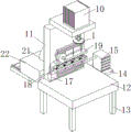
FIG. 1 is a schematic perspective view of a support frame according to the present utility model;
FIG. 2 is a schematic view of a connecting rod structure according to the present utility model;
FIG. 3 is a schematic diagram of a clamping block according to the present utility model;
FIG. 4 is a schematic view of a conveying pipe structure in the utility model;
FIG. 5 is a schematic view of the structure of the collecting box in the present utility model;
fig. 6 is a schematic view of the structure of the suction port in the present utility model;
FIG. 7 is a schematic view of a cleaning brush according to the present utility model;
FIG. 8 is a schematic view of the structure of the extrusion block in the present utility model.
In the figure: 1. a grinding machine; 10. a first electrical push rod; 11. a support frame; 12. a table body; 13. a support leg; 14. a support plate; 15. a second electric push rod; 16. a clamping groove; 17. a pushing block; 18. a connecting block; 19. a clamping block; 110. a connecting rod; 2. an air suction port; 21. a delivery tube; 22. a mounting box; 23. a water conduit; 24. a water outlet hole; 25. a servo motor; 26. a fan blade; 3. a chute; 31. a telescopic rod; 32. a damping spring; 33. extruding a block; 34. a rubber pad; 4. a connecting rod; 41. a handle; 5. a discharge port; 51. a collection box; 52. a handle; 6. a trapezoid groove; 61. a trapezoid block; 7. a mounting plate; 71. a cleaning brush; 72. a dust collection groove.
Detailed Description
The following description of the embodiments of the present utility model will be made clearly and completely with reference to the accompanying drawings, in which it is apparent that the embodiments described are only some embodiments of the present utility model, but not all embodiments. All other embodiments, which can be made by those skilled in the art based on the embodiments of the utility model without making any inventive effort, are intended to be within the scope of the utility model.
Referring to fig. 1 to 8, a polishing device for a chair surface includes a polishing machine 1; a first electric push rod 10 is arranged at the top end of the grinding machine 1; the bottom end of the first electric push rod 10 is fixedly connected with a supporting frame 11; one end of the supporting frame 11 is fixedly connected with a table body 12; a plurality of groups of supporting legs 13 are fixedly connected to the bottom end of the table body 12; a supporting plate 14 is fixedly connected to one side of the table body 12; a second electric push rod 15 is fixedly connected to the top end of the supporting plate 14; a push block 17 is fixedly connected to one end of the second electric push rod 15; a clamping groove 16 is fixedly connected to one side of the supporting frame 11; the push block 17 is connected with the clamping groove 16 in a sliding manner; the other end of the pushing block 17 is fixedly connected with a connecting block 18; a clamping block 19 is hinged to one side of the connecting block 18; a connecting rod 110 is hinged to the top end of the clamping block 19; one end of the connecting rod 110 is hinged with the supporting frame 11; in operation, the support legs 13 can support the table body 12, the support plates 14 can be supported by the table body 12, and the second electric push rod 15 can be supported by the support plates 14; through ejecting to promote pusher 17, through promoting pusher 17, thereby can slide in draw-in groove 16, can play the effect of direction through draw-in groove 16, can connect grip block 19 through connecting block 18, when promoting, can drive connecting rod 110 and remove, move through connecting rod 110 approach, thereby can drive grip block 19 and overturn automatically, can support first electric putter 10 through support frame 11, stretch out through first electric putter 10, thereby drive polisher 1 and descend, descend through polisher 1, thereby can polish the another side of seat, not only easy operation through this design, moreover can overturn the seat surface automatically, thereby can polish the processing to the another side of seat, thereby save process time.
Further, as shown in fig. 1, 4, 5 and 6, an air suction port 2 is formed on one side of the supporting frame 11; a conveying pipe 21 is fixedly connected to one side of the air suction port 2; the other end of the conveying pipe 21 is fixedly connected with a mounting box 22; a water guide pipe 23 is fixedly connected to the top end of the conveying pipe 21; a plurality of groups of water outlet holes 24 are formed in the inner side of the conveying pipe 21; the water guide pipe 23 is connected with the water outlet hole 24; a servo motor 25 is fixedly connected to the inner side of the installation box 22; the output end of the servo motor 25 is fixedly connected with a plurality of groups of fan blades 26; during operation, be connected with external water source through aqueduct 23, can support servo motor 25 through install bin 22, reverse through servo motor 25, thereby drive flabellum 26 and rotate, thereby can collect the piece of polishing through induction port 2, carry through conveyer pipe 21, lead to the apopore 24 to spout through aqueduct 23 with the water source, thereby can wet the piece of absorbing, can collect the piece of polishing through this design, in the collection, can wet the piece, thereby can reduce the piece and fly in the air, reduce the staff and inhale the piece and cause the damage with the piece health.
Further, as shown in fig. 8, the inner side of the clamping block 19 is symmetrically provided with a chute 3; a plurality of groups of telescopic rods 31 are fixedly connected to the inner side of the sliding groove 3; a plurality of groups of shock absorption springs 32 are sleeved at the middle part of the telescopic rod 31; an extrusion block 33 is fixedly connected to one end of the telescopic rod 31; a rubber pad 34 is fixedly connected to one side of the extrusion block 33; during operation, through putting the seat board in grip block 19, mutually supporting through telescopic link 31 and bradyseism spring 32 to drive extrusion piece 33 and slide in spout 3, thereby can carry out the centre gripping to the seat board through extrusion piece 33, can increase frictional force through rubber pad 34, can carry out the centre gripping to the seat board of different size models fixedly through this design, thereby can reduce the phenomenon that takes place to rock when polishing.
Further, as shown in fig. 8, a connecting rod 4 is fixedly connected to one side of the extrusion block 33; the other end of the connecting rod 4 is fixedly connected with a handle 41; during operation, the staff pulls the connecting rod 4 through the handle 41 to can stimulate the grip block 19, alright take out the seat board, finish the back to the seat board through this design, be convenient for the staff to take the seat board.
Further, as shown in fig. 5, a plurality of groups of discharge ports 5 are formed on the inner side of the installation box 22; the bottom end of the installation box 22 is connected with a collection box 51 in a sliding manner; a handle 52 is fixedly connected to one side of the collecting box 51; during operation, can discharge the piece that falls that wets through bin outlet 5, can collect the piece that falls through collecting box 51, can connect handle 52 through collecting box 51, can collect the sweeps that falls through this design, then clear up in unison to can reduce and cause the pollution to the environment.
Further, as shown in fig. 5, a trapezoid groove 6 is symmetrically formed on one side of the installation box 22; trapezoidal blocks 61 are symmetrically and fixedly connected to the two sides of the collecting box 51; the trapezoid block 61 is connected with the trapezoid groove 6 in a sliding manner; during operation, the trapezoidal blocks 61 are taken out of the trapezoidal grooves 6 by the staff through the handles 52, so that the collecting box 51 can be taken out, and the collecting box 51 is convenient to install and disassemble by the staff through the design, so that the staff can use the collecting box conveniently.
Further, as shown in fig. 7, one side of the pushing block 17 is fixedly connected with a mounting plate 7; a plurality of groups of cleaning brushes 71 are fixedly connected to the bottom end of the mounting plate 7; a dust collection groove 72 is formed in the inner side of the clamping groove 16; during operation, can connect the cleaning brush 71 through mounting panel 7, when removing through ejector pad 17 to drive cleaning brush 71 and clear up draw-in groove 16, can collect through dust collection groove 72, can clear up draw-in groove 16 voluntarily through this design, thereby improved the practicality.
The working principle is that the supporting leg 13 can support the table body 12, the supporting plate 14 can be supported by the table body 12, and the second electric push rod 15 can be supported by the supporting plate 14; pushing out the pushing block 17, pushing the pushing block 17, sliding in the clamping groove 16, guiding through the clamping groove 16, connecting the clamping block 19 through the connecting block 18, pushing, driving the connecting rod 110 to move, driving the clamping block 19 to automatically overturn through the moving of the connecting rod 110, supporting the first electric push rod 10 through the supporting frame 11, extending out through the first electric push rod 10, driving the grinding machine 1 to descend, descending through the grinding machine 1, grinding the other surface of the seat, connecting with an external water source through the water guide pipe 23, supporting the servo motor 25 through the mounting box 22, reversing through the servo motor 25, driving the fan blade 26 to rotate, collecting the ground scraps through the air suction port 2, conveying through the conveying pipe 21, the water source is guided to the water outlet hole 24 through the water guide pipe 23 to be sprayed out so as to wet absorbed scraps, the seat plate is placed in the clamping block 19, the telescopic rod 31 and the cushioning spring 32 are matched with each other so as to drive the extrusion block 33 to slide in the chute 3, the seat plate can be clamped through the extrusion block 33, the friction force can be increased through the rubber pad 34, a worker pulls the connecting rod 4 through the handle 41 so as to pull the clamping block 19, the seat plate can be taken out, the wet fallen scraps can be discharged through the discharge port 5, the fallen scraps can be collected through the collecting box 51, the handle 52 can be connected through the collecting box 51, the trapezoid block 61 can be taken out from the trapezoid groove 6 through the handle 52, the collecting box 51 can be taken out, the cleaning brush 71 can be connected through the mounting plate 7, the cleaning brush 71 is driven to clean the clamping groove 16 while the pushing block 17 moves, and the cleaning brush can collect dust through the dust collection groove 72.
The foregoing has shown and described the basic principles, principal features and advantages of the utility model. It will be understood by those skilled in the art that the present utility model is not limited to the embodiments described above, and that the above embodiments and descriptions are merely illustrative of the principles of the present utility model, and various changes and modifications may be made without departing from the spirit and scope of the utility model, which is defined in the appended claims.
Claims (6)
1. A polishing device for a chair surface, comprising a polishing machine (1); the method is characterized in that: a first electric push rod (10) is arranged at the top end of the grinding machine (1); the bottom end of the first electric push rod (10) is fixedly connected with a supporting frame (11); one end of the supporting frame (11) is fixedly connected with a table body (12); the bottom end of the table body (12) is fixedly connected with a plurality of groups of supporting legs (13); a supporting plate (14) is fixedly connected to one side of the table body (12); the top end of the supporting plate (14) is fixedly connected with a second electric push rod (15); one end of the second electric push rod (15) is fixedly connected with a push block (17); a clamping groove (16) is fixedly connected to one side of the supporting frame (11); the pushing block (17) is connected with the clamping groove (16) in a sliding manner; the other end of the pushing block (17) is fixedly connected with a connecting block (18); one side of the connecting block (18) is hinged with a clamping block (19); a connecting rod (110) is hinged to the top end of the clamping block (19); one end of the connecting rod (110) is hinged with the supporting frame (11).
2. A chair surface polishing apparatus as claimed in claim 1, wherein: an air suction port (2) is formed in one side of the supporting frame (11); a conveying pipe (21) is fixedly connected to one side of the air suction port (2); the other end of the conveying pipe (21) is fixedly connected with a mounting box (22); a water guide pipe (23) is fixedly connected to the top end of the conveying pipe (21); a plurality of groups of water outlet holes (24) are formed in the inner side of the conveying pipe (21); the water guide pipe (23) is connected with the water outlet hole (24); a servo motor (25) is fixedly connected to the inner side of the mounting box (22); the output end of the servo motor (25) is fixedly connected with a plurality of groups of fan blades (26).
3. A chair surface polishing apparatus as claimed in claim 2, wherein: a chute (3) is symmetrically arranged on the inner side of the clamping block (19); a plurality of groups of telescopic rods (31) are fixedly connected to the inner side of the sliding groove (3); the middle part of the telescopic rod (31) is sleeved with a plurality of groups of damping springs (32); one end of the telescopic rod (31) is fixedly connected with an extrusion block (33); one side of the extrusion block (33) is fixedly connected with a rubber pad (34).
4. A chair surface polishing apparatus according to claim 3, wherein: a connecting rod (4) is fixedly connected to one side of the extrusion block (33); the other end of the connecting rod (4) is fixedly connected with a handle (41).
5. A chair surface polishing apparatus as claimed in claim 4, wherein: a plurality of groups of discharge ports (5) are formed in the inner side of the mounting box (22); the bottom end of the installation box (22) is connected with a collection box (51) in a sliding manner; a handle (52) is fixedly connected to one side of the collecting box (51).
6. A chair surface polishing apparatus as claimed in claim 5, wherein: one side of the installation box (22) is symmetrically provided with a trapezoid groove (6); trapezoidal blocks (61) are symmetrically and fixedly connected to the two sides of the collecting box (51); the trapezoid block (61) is connected with the trapezoid groove (6) in a sliding mode.
Priority Applications (1)
| Application Number | Priority Date | Filing Date | Title |
|---|---|---|---|
| CN202320837237.XU CN219255153U (en) | 2023-04-15 | 2023-04-15 | Polishing device for chair surface |
Applications Claiming Priority (1)
| Application Number | Priority Date | Filing Date | Title |
|---|---|---|---|
| CN202320837237.XU CN219255153U (en) | 2023-04-15 | 2023-04-15 | Polishing device for chair surface |
Publications (1)
| Publication Number | Publication Date |
|---|---|
| CN219255153U true CN219255153U (en) | 2023-06-27 |
Family
ID=86854115
Family Applications (1)
| Application Number | Title | Priority Date | Filing Date |
|---|---|---|---|
| CN202320837237.XU Active CN219255153U (en) | 2023-04-15 | 2023-04-15 | Polishing device for chair surface |
Country Status (1)
| Country | Link |
|---|---|
| CN (1) | CN219255153U (en) |
-
2023
- 2023-04-15 CN CN202320837237.XU patent/CN219255153U/en active Active
Similar Documents
| Publication | Publication Date | Title |
|---|---|---|
| CN111644940B (en) | Processing production line of plank | |
| CN109107993B (en) | Ash and dust removal device of industrial automation equipment | |
| CN112621432B (en) | Wood grinding device for furniture processing | |
| CN215317821U (en) | Polishing device with chip cleaning mechanism for refrigeration accessories | |
| CN219255153U (en) | Polishing device for chair surface | |
| CN212553022U (en) | Wall body grinding device for civil engineering convenient to use | |
| CN110974095A (en) | Wall body environmental protection ornamental material surface floating dust cleaning device | |
| CN216179138U (en) | Steel door plate edge grinding and leveling device | |
| CN214135269U (en) | Environment-friendly joint line grinding device with dust collection structure | |
| CN212444523U (en) | Edging device is used in plastic products processing | |
| CN208788183U (en) | A kind of dust-protection type bamboo wood furniture production grinding device | |
| CN116900880B (en) | Polishing device for welding net processing | |
| CN219358856U (en) | Pipe cutting equipment capable of collecting scraps | |
| CN220561083U (en) | Surface polishing structure for woodwork processing | |
| CN215250947U (en) | Brushing device for microfiber leather sueding machine | |
| CN220145588U (en) | PVC wood-plastic plate traction type polishing equipment | |
| CN219684845U (en) | Effectual grinder of retrieving dust saw-dust | |
| CN216138635U (en) | Plastic block surface polishing equipment with good dust removal effect | |
| CN221539154U (en) | Indoor wall top polishing device | |
| CN214555499U (en) | Surface cleaning device for leather art engraving | |
| CN220240933U (en) | Surface grinding machine with self-cleaning function | |
| CN215236458U (en) | Surface dust removal device for processing connecting plate | |
| CN211681285U (en) | Carbon fiber plate polishing platform | |
| CN216298885U (en) | Polishing device capable of cleaning raised dust for machining automobile chassis | |
| CN219275483U (en) | Polishing and chip removing device |
Legal Events
| Date | Code | Title | Description |
|---|---|---|---|
| GR01 | Patent grant | ||
| GR01 | Patent grant |