Mud-water separation device for sewage tank
Technical Field
The utility model belongs to the field of vehicle-mounted sewage tanks, and particularly relates to a mud-water separation device for a sewage tank.
Background
The vehicle-mounted sewage tank is a container for sucking and temporarily storing deposited sewage, sludge and garbage of the urban domestic sewage system, is generally arranged on a vehicle chassis, sucks sewage, sludge, garbage and the like in municipal pipe networks, septic tanks and the like into the sewage tank through a suction pump and a suction pipe, performs solid-liquid separation on sucked sewage, sludge and the like through a solid-liquid separation device arranged in the sewage tank when the sewage carried in the sewage tank is more, and then discharges liquid after the solid-liquid separation into the sewage system, so that the sewage tank can be filled with more sewage.
At present, a device for carrying out solid-liquid separation on sewage by a sewage tank is commonly used as a filter screen, but the filter screen is often entangled or accumulated and blocked by sundries such as fibers, plastic bags, paper, vegetable leaves and the like in the sewage, which can greatly reduce the solid-liquid separation efficiency and even lead to operation stop. Once the operation is stopped, dirt suction operation can be performed again only after the plugs in the filter screen are removed. And removing the plugs from the screen increases the amount of labor for the worker and is time consuming.
Disclosure of Invention
The utility model aims to overcome the defects in the prior art, and provides a mud-water separation device for a sewage tank, which solves the problem of blockage of a filter screen of the mud-water separation device and improves the solid-liquid separation efficiency.
In order to achieve the above purpose, the present utility model provides the following technical solutions: the utility model provides a mud-water separation device for sewage tank, includes the sewage tank, set up mud-water separation device on the rear end tank cover of sewage tank, mud-water separation device's front end passes the rear end tank cover and extends into the sewage tank, mud-water separation device includes double-deck barrel, shaftless spiral device and is used for driving shaftless spiral device rotatory drive arrangement, double-deck barrel comprises outer barrel and inner tube, be the intermediate layer space between outer barrel and the inner tube, the rear end of double-deck barrel is sealed with the back shrouding, the front end in intermediate layer space is sealed with preceding shrouding, makes the intermediate layer space form the enclosure space, be equipped with a plurality of filtration pore on the inner tube, back shrouding outer end fixed bearing seat; the utility model discloses a sewage treatment device, including shaftless screw device, bearing, outer barrel, bearing, sealing plate, bearing seat, water outlet, supporting rod, bearing seat, outer barrel lower extreme fixed connection supporting rod, shaftless screw device's shaftless screw blade one end fixed connection, shaftless screw blade is located the inner barrel for with debris push back in the sewage tank in the sewage, the supporting rod extends back shrouding and passes through the bearing cooperation with the bearing seat, the overhanging end of supporting rod is connected with a drive arrangement, end cover fixed connection of drive arrangement and bearing seat, outer barrel lower extreme is equipped with the outlet, this outlet and drain pipe intercommunication.
Preferably, the upper end of outer barrel is equipped with the wash pipe, wash pipe and intermediate layer space intercommunication, set up the connector on the wash pipe for connect the high-pressure water pipe.
Preferably, the cleaning pipe penetrates through the rear end tank cover and extends along the axial direction of the outer cylinder body, and at least two spray holes of the cleaning pipe are communicated with the interlayer space.
Preferably, the water outlet at the lower end of the outer cylinder body is connected with a water drain pipe through a water collecting tank arranged on the inner wall of the tank cover at the rear end.
Preferably, the water collection tank is connected with the drain pipe through a drain pump.
Preferably, a waterproof sealing element is arranged between the supporting rod and the rear sealing plate and between the supporting rod and the bearing seat, and is used for sealing a gap between the supporting rod and the rear sealing plate and between the supporting rod and the bearing seat.
Preferably, the extending end of the supporting rod is provided with a spline, and the supporting rod is connected with a shaft spline of the driving device through the spline.
Preferably, the driving device is an electric motor or a hydraulic motor.
Preferably, the filtering holes are round holes or strip-shaped holes.
Preferably, the mud-water separation device is positioned at the upper half part of the sewage tank.
By adopting the scheme, the mud-water separation device is arranged on the rear end tank cover of the sewage tank, the front end of the mud-water separation device penetrates through the rear end tank cover and extends into the sewage tank, the mud-water separation device consists of a double-layer cylinder body, a shaftless screw device and a driving device, the double-layer cylinder body consists of an outer cylinder body and an inner cylinder body, an interlayer space is formed between the outer cylinder body and the inner cylinder body, and the interlayer space is a closed space; the inner cylinder body is provided with a plurality of filtering holes, and impurities such as sewage, fibers, plastic bags, paper, vegetable leaves and the like can be separated through the filtering holes, so that the impurities such as the fibers, the plastic bags, the paper, the vegetable leaves and the like cannot enter the interlayer space. The device comprises an inner cylinder body, a supporting rod, a driving device, an end cover fixedly connected with the end cover of the bearing seat, a supporting rod, a water outlet and a water draining pipe, wherein one end of the shaftless screw is fixedly connected with the supporting rod, one end of the shaftless screw is positioned in the inner cylinder body and used for pushing sundries in sewage back into the sewage tank, the supporting rod extends out of the inner cylinder body and is matched with the bearing seat through the bearing, the overhanging end of the supporting rod is connected with the driving device, the driving device is fixedly connected with the end cover of the bearing seat, and the shaftless screw is driven to rotate under the action of the driving device, so that the shaftless screw can push sundries such as fibers, plastic bags, paper, vegetable leaves and the like which enter the inner cylinder body back into the sewage tank, and separated liquid is discharged from an interlayer space through the water draining pipe.
The upper end of the outer cylinder body is provided with a cleaning pipe which is communicated with the interlayer space, a connector is arranged on the cleaning pipe and used for connecting a high-pressure water pipe, the cleaning pipe penetrates through the rear end tank cover of the sewage tank and extends along the axial direction of the outer cylinder body, and at least two spray holes of the cleaning pipe are communicated with the interlayer space. The water is supplied through the cleaning pipe, so that the sludge in the interlayer space and the filter holes can be cleaned, the filter holes are prevented from being blocked by the sludge, and the solid-liquid fraction efficiency is influenced.
The water outlet at the lower end of the outer cylinder body is provided with a water collecting tank on the inner wall of the tank cover, and the water draining pump is arranged below the water collecting tank and connected with the water draining pipe through the water draining pump. The filtered sewage enters the water collecting tank through the water outlet, can be accumulated in the water collecting tank for a short time without being discharged when the water quantity is small, and can be discharged from the water outlet pipe through the water discharging pump when the water quantity is large.
By adopting the device, the filter screen can be effectively prevented from being blocked by sundries, and the solid-liquid fraction efficiency is improved.
Drawings
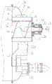
FIG. 1 is a schematic diagram of the structure of the present utility model;
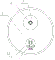
fig. 2 is a schematic view of the rear end of the sewage tank of the present utility model.
In the figure: 1 is a sewage tank, 1a is a rear end tank cover, 2 is a mud-water separation device, 3 is a shaftless screw device, 3a is a shaftless screw blade, 3b is a bearing rod, 4 is a driving device, 5 is an interlayer space, 6 is an outer cylinder, 7 is an inner cylinder, 7a is a filtering hole, 8 is a rear sealing plate, 9 is a front sealing plate, 10 is a bearing seat, 11 is an end cover, 12 is a water collecting tank, 12a is a water outlet, 13 is a drainage pump, 14 is a drainage pipe, 15 is a cleaning pipe, 16 is a connector, and 17 is a waterproof sealing piece.
Detailed Description
Referring to fig. 1 and 2, an embodiment of a mud-water separation device for a sewage tank comprises a sewage tank 1 and a mud-water separation device 2, wherein the mud-water separation device 2 is arranged on a rear end tank cover 1a of the sewage tank 1, the front end of the mud-water separation device 2 penetrates through the rear end tank cover 1a to extend into the sewage tank 1, and the mud-water separation device 2 is positioned on the upper half part of the sewage tank 1 so as to improve the filtering capacity of sewage in the tank and increase the solid sewage volume in the tank. The mud-water separation device 2 comprises a double-layer cylinder body, a shaftless spiral device 3 and a driving device 4 for driving the shaftless spiral device 3 to rotate, wherein the double-layer cylinder body consists of an outer cylinder body 6 and an inner cylinder body 7, an interlayer space 5 is arranged between the outer cylinder body 6 and the inner cylinder body 7, a rear end welding rear sealing plate 8 of the double-layer cylinder body is sealed, and a front end welding front sealing plate 9 of the interlayer space 5 is sealed, so that the interlayer space 5 forms a sealing space. The inner cavity of the inner cylinder 7 is communicated with the inner cavity of the sewage tank 1. The inner cylinder 7 is provided with a plurality of filtering holes 7a, and impurities such as sewage, fibers, plastic bags, paper, vegetable leaves and the like can be separated through the filtering holes 7a, so that the impurities such as the fibers, the plastic bags, the paper, the vegetable leaves and the like cannot enter the interlayer space 5. The filtering holes 7a can be round holes or strip-shaped holes, the diameter of the round holes is not smaller than 3mm, and the length of the strip-shaped holes is not more than 30mm. The bearing seat 10 is fixed at the outer end of the rear sealing plate 8, the shaftless screw device 3 comprises shaftless screw blades 3a and supporting rods 3b which are fixedly connected into a whole, one end of each shaftless screw blade 3a is fixedly connected with each supporting rod 3b, and each shaftless screw blade 3a is positioned in the inner cylinder 7 and used for pushing sundries in sewage back into the sewage tank, so that sundries are prevented from blocking the filtering holes, and the solid-liquid separation efficiency is improved. The shaft hole arranged on the back sealing plate 8 extending out of the supporting rod 3b is matched with the bearing seat 10 through a bearing, the overhanging end of the supporting rod 3b is connected with a driving device 4, the driving device 4 is fixedly connected with an end cover 11 of the bearing seat 10, the end cover 11 of the bearing seat 10 is connected with the bearing seat 10 through a bolt, and the driving device 4 is an electric motor or a hydraulic motor. The extending end of the support rod 3b of the present embodiment is provided with a spline, and is connected with the shaft of the driving device 4 through the spline, and of course, the support rod 3b may be connected and fixed with the shaft of the driving device 4 through a flange or a flat key. A waterproof sealing member 17 is arranged between the supporting rod 3b and the rear sealing plate 8 and the bearing seat 10, and is used for sealing a gap between the supporting rod 3b and the rear sealing plate 8 and the bearing seat 10. The lower end of the outer cylinder 6 is provided with a drain port 12a, and the drain port 12a communicates with a drain pipe 14. Alternatively, a water collection tank 12 may be provided on the inner wall of the rear end cap 1a, the water discharge port 12a at the lower end of the outer cylinder 6 may communicate with the water collection tank 12, and the water discharge pipe 14 may be connected to the lower portion of the water collection tank 12. A drain pump 13 may also be disposed on the water collection tank 12, and the water collection tank 12 is connected to a drain pipe 14 through the drain pump 13. The lower part of the rear end tank cover 1a is provided with a concave cavity, and the drainage pump 13 is fixedly arranged in the concave cavity and communicated with the water collection tank 12. This allows the separated liquid to be discharged through the interlayer space 5 sequentially through the water collection tank 12, the drain pump 13 and the drain pipe 14.
The upper end of the outer cylinder body 6 is also provided with a cleaning pipe 15, the cleaning pipe 15 penetrates through a through hole formed in the rear end tank cover 1a to extend along the axial direction of the outer cylinder body 6, the through hole in the rear end tank cover 1a is welded and sealed after the cleaning pipe 15 penetrates through, one part of the cleaning pipe 15 is positioned in the sewage tank 1, the other part of the cleaning pipe is positioned outside the rear end tank cover 1a, the cleaning pipe 15 is communicated with the interlayer space 5, at least two spray holes of the cleaning pipe 15 are communicated with the interlayer space 5, a connector 16 is arranged at the part of the cleaning pipe 15 positioned outside the rear end tank cover 1a, and the connector 16 is used for connecting a high-pressure water pipe. The high-pressure water is supplied through the cleaning pipe 15, so that the sludge in the interlayer space and on the filter holes can be cleaned, the filter holes are prevented from being blocked by the sludge, and the solid-liquid fraction efficiency is influenced.
When the sewage tank 1 is in operation, after sewage is sucked in, the driving device 4 is started to drive the shaftless screw device 3 to rotate when the sucked sewage gradually increases to the upper half part of the sewage tank 1 and liquid is required to be discharged, solid impurities such as fibers mixed in the sewage entering the inner cylinder 7 of the mud-water separation device 2 are pushed back into the sewage tank 1 by the shaftless screw blade 3a of the shaftless screw device 3, so that the filtered sewage enters the water collecting tank 12 through the water outlet 12a on the outer cylinder 6 and then enters the water outlet pipe 14 through the water discharging pump 13 to be discharged, and mud-water separation efficiency is ensured. When the mud-water separation device 2 needs to be cleaned, the cleaning pipe 15 is used for cleaning the interlayer space 5 of the mud-water separation device 2 by adopting high-pressure water, so that the filter holes 7a on the inner cylinder 7 are prevented from being blocked, and the dirt sucking working efficiency is improved.
The above-mentioned embodiments are only embodiments of the present utility model, and the present device can improve the work efficiency of dirt suction, prevent the mud-water separation device from being blocked, and reduce the labor capacity of the staff. Modifications and improvements will readily occur to those skilled in the art without departing from the scope of the utility model, and it is intended to cover all such modifications and improvements as would be within the true scope of the utility model.