CN219241026U - Building decoration furred ceiling system convenient to loading and unloading - Google Patents
Building decoration furred ceiling system convenient to loading and unloading Download PDFInfo
- Publication number
- CN219241026U CN219241026U CN202320056814.1U CN202320056814U CN219241026U CN 219241026 U CN219241026 U CN 219241026U CN 202320056814 U CN202320056814 U CN 202320056814U CN 219241026 U CN219241026 U CN 219241026U
- Authority
- CN
- China
- Prior art keywords
- ceiling system
- keel frame
- buckle plate
- buckle
- connecting piece
- Prior art date
- Legal status (The legal status is an assumption and is not a legal conclusion. Google has not performed a legal analysis and makes no representation as to the accuracy of the status listed.)
- Active
Links
Images


Abstract
The utility model discloses a building decoration suspended ceiling system convenient to assemble and disassemble, which comprises a keel frame, wherein a plurality of threaded mounting holes are formed in the upper end face of the keel frame, a supporting rod is detachably arranged on the threaded mounting holes, a plurality of U-shaped mounting grooves are formed in the lower end face of the keel frame, a U-shaped limiting block is arranged in each U-shaped mounting groove, connecting pieces are connected in the U-shaped mounting grooves, a buckle plate is connected below each connecting piece in a hanging mode, the supporting rod is composed of a connecting base, a rotating nut, a threaded rod and a mounting plate, the distance between the keel frame and a wall body can be adjusted through the rotating nut, the connecting pieces are optionally arranged in the proper U-shaped mounting grooves, a bidirectional hook arranged at the lower end of each connecting piece is connected with a hanging groove formed in the buckle plate in a hanging mode, a connecting block and a connecting port are arranged on the buckle plate, the adjacent buckle plates are spliced to ensure the overall flatness, the distance between each buckle plate and the buckle plate is adjustable, and the rear maintenance and the buckle plate are convenient.
Description
Technical Field
The utility model relates to the technical field of building suspended ceilings, in particular to a building decoration suspended ceiling system convenient to assemble and disassemble.
Background
The suspended ceiling is one of the important parts of the decoration of the top of the living environment of a house, and is simply the decoration of an installation ceiling, at present, the interior roof decoration generally adopts the mode of an integrated suspended ceiling, the suspended ceiling has the functions of heat preservation, heat insulation, sound insulation and the like, meanwhile, the suspended ceiling is used as a concealed layer of electric, ventilation air conditioning, communication, fire prevention and alarm equipment pipelines, the Chinese patent discloses a detachable building decoration suspended ceiling system (authorized bulletin number CN 208844776U), the patent discloses a detachable building decoration suspended ceiling system, which comprises a keel bracket, a suspended ceiling groove and a movable cover plate, the side ends and two sides of the keel bracket are provided with connecting grooves, the suspended ceiling groove is arranged on the side sides of the keel bracket, a fixed rod is arranged in the suspended ceiling plate, the movable cover plate is arranged at the bottom of the suspended ceiling plate, a reset spring is arranged at the joint of the movable cover plate and the suspended ceiling plate, the top edge of the keel bracket is provided with a mounting groove, the mounting groove is positioned above the suspended ceiling groove, the mounting groove is internally provided with a supporting base, the outer side of the supporting base is provided with a supporting bolt, the supporting base is fixedly provided with the supporting rod, and the two ends of the supporting base are fixedly connected with the supporting rods, and the other supporting plate is provided with the supporting plate. This detachable architectural decoration furred ceiling system through the support base and the mounting groove that set up, makes things convenient for the installation and the dismantlement of fossil fragments, through the spring and the cardboard that set up, makes things convenient for the fixed and the dismantlement of furred ceiling board.
This patent can be convenient for the installation and the dismantlement of fossil fragments, but the complicated installation of structure is comparatively troublesome with the dismantlement, supports base and bracing piece in addition and all do not have the adjustability, just can not adjust the height and the position of fossil fragments according to actual conditions after the installation, consequently can bring a great deal of inconvenience at the in-process of installation furred ceiling, has reduced work efficiency.
Disclosure of Invention
The utility model provides a convenient-to-assemble and disassemble building decoration suspended ceiling system, which aims to solve the problems of
The problems of inconvenience in installation, reduction in working efficiency and the like caused by complex disassembly, incapability of adjusting the height and the position of the keels are solved in the background technology.
In order to solve the problem, the utility model provides a building decoration furred ceiling system convenient to loading and unloading, including the keel frame, the keel frame up end seted up a plurality of screw thread mounting holes, screw thread mounting hole on demountable installation have the bracing piece, the keel frame down the terminal surface seted up a plurality of U type mounting grooves, U type mounting groove in be equipped with U type stopper, U type mounting groove in-connection have the connecting piece, the connecting piece below articulates there is the buckle.
Preferably: the supporting rod comprises a connecting base, a rotating nut, a threaded rod and a mounting plate, wherein the connecting base is a hollow cylinder, one end of the connecting base is in a threaded shape and is spirally connected in a threaded mounting hole on the keel frame, the rotating nut is rotatably clamped with the other end of the connecting base, one end of the threaded rod is spirally connected in the rotating nut, and the other end of the threaded rod is welded with the mounting plate.
Preferably: the connecting piece top be equipped with first spout, connecting piece top connect in U type mounting groove, and first spout cooperatees with U type stopper, connecting piece bottom symmetry be equipped with two-way couple.
Preferably: two hanging grooves are symmetrically formed in two symmetrical edges of one buckle plate respectively, a connecting block and a connecting port are formed in two symmetrical edges of the other buckle plate respectively, the positions of the connecting blocks formed in two sides are opposite to those of the connecting ports, and the connecting blocks are spliced with the connecting ports on the adjacent buckle plates.
Preferably: the bidirectional hook at the bottom of the connecting piece is connected with a hanging groove on the buckle plate.
Preferably: a positioning piece is connected to the U-shaped mounting groove on the keel frame through a bolt, one end of the positioning piece is in an arc notch shape, an arc limiting block is arranged in the arc notch, second sliding grooves are symmetrically formed in two sides of the positioning piece, the second sliding grooves are matched with the U-shaped limiting blocks in the U-shaped mounting groove, and the arc limiting blocks formed in the arc notch ends of the positioning piece are matched with the first sliding grooves at the tops of the connecting pieces in a propping mode.
The beneficial effects of adopting above technical scheme are:
1. the length of screw rod is adjusted to the rotatory nut on the bracing piece to be convenient for adjust the distance between keel frame and the wall body top when being under construction, with the height and the planarization of guaranteeing the buckle, adjust keel frame and bracing piece's mounted position through the screw thread mounting hole at keel frame top in addition.
2. The U-shaped mounting groove formed in the lower end face of the keel frame is convenient for the connecting piece to be mounted at a proper position in construction, the connecting piece is prevented from moving easily through the action of the U-shaped limiting block and the arc-shaped positioning block on the positioning piece, and the stability of the buckling plate is guaranteed.
3. The connecting blocks and the connecting ports on the buckle plates are respectively spliced with the connecting ports and the connecting blocks on the adjacent buckle plates, so that the integrity and the flatness between the plurality of buckle plates are further ensured.
4. The pinch plates are installed one by one, so that the suspended ceiling system is convenient to maintain in the later period and the pinch plates are convenient to replace.
Drawings
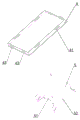
Fig. 1 is a schematic perspective view of the present utility model.
Fig. 2 is an enlarged schematic view of a partial structure of the present utility model.
FIG. 3 is a schematic view of part of the structure of the present utility model.
Wherein: 1-a keel frame; 11-a threaded mounting hole; 12-U-shaped mounting grooves; a 121-U-shaped limiting block; 2-supporting rods; 21-connecting the base; 22-rotating the nut; 23-a threaded rod; 24-mounting plates; 3-connectors; 31-a first chute; 32-a bidirectional hook; 4-buckle plates; 41-hanging grooves; 42-connecting blocks; 43-connecting blocks; 5-positioning pieces; 51-arc limiting blocks; 52-second chute.
Detailed Description
Embodiments of the present utility model will be described in detail below with reference to the accompanying drawings.
As shown in fig. 1-3, in this embodiment, a building decoration suspended ceiling system convenient to loading and unloading, including keel frame 1, keel frame 1 up end seted up a plurality of screw thread mounting holes 11, screw thread mounting holes 11 on demountable installation have bracing piece 2, keel frame 1 lower terminal surface seted up a plurality of U type mounting grooves 12, U type mounting groove 12 in be equipped with U type stopper 121, U type mounting groove 12 in be connected with connecting piece 3, connecting piece 3 below articulates buckle 4.
Preferably: the supporting rod 2 is composed of a connecting base 21, a rotating nut 22, a threaded rod 23 and a mounting plate 24, wherein the connecting base 21 is a hollow cylinder, one end of the connecting base 21 is in a threaded shape and is spirally connected in a threaded mounting hole 12 on the keel frame 1, the rotating nut 22 is rotatably clamped with the other end of the connecting base 21, one end of the threaded rod 23 is spirally connected in the rotating nut 22, and the other end of the threaded rod is welded with the mounting plate 24.
Preferably: the top end of the connecting piece 3 is provided with a first sliding groove 31, the top 3 end of the connecting piece is connected in the U-shaped mounting groove 12, the first sliding groove 31 is matched with the U-shaped limiting block 121, and two-way hooks 32 are symmetrically arranged at the bottom of the connecting piece 3.
Preferably: two hanging grooves 41 are symmetrically formed on two symmetrical edges of the buckle plate 4 respectively, a connecting block 42 and a connecting port 43 are formed on two symmetrical edges of the buckle plate 4 respectively, the positions of the connecting blocks 42 formed on two sides are opposite to those of the connecting ports 43, and the connecting blocks 42 are spliced with the connecting ports 43 on the adjacent buckle plates 4.
Preferably: the bidirectional hook 32 at the bottom 3 of the connecting piece is hung with a hanging groove 41 on the buckle plate 4.
Preferably: a locating piece 5 is connected to the U-shaped mounting groove 12 on the keel frame 1 through bolts, one end of the locating piece 5 is in an arc notch shape, an arc limiting block 51 is arranged in the arc notch, second sliding grooves 52 are symmetrically formed in two sides of the locating piece 5, the second sliding grooves 52 are matched with the U-shaped limiting blocks 121 in the U-shaped mounting groove 12, and the arc limiting blocks 51 formed in the arc notch end of the locating piece 5 are matched with the first sliding grooves 31 at the top of the connecting piece 3 in a propping mode.
The implementation is implemented as follows:
this application is when using, buckle 4 hang mutually with the two-way couple 32 of connecting piece 3 bottom through hanging groove 41, form the whole connection in connecting port 43 through connecting block 42 grafting between the adjacent buckle 4, a buckle 4 uses four connecting pieces 3 to guarantee the stability of buckle 4 when hanging, the top of connecting piece 3 is equipped with first spout 31, connecting piece 3 according to the actual conditions of construction select suitable U type mounting groove 12, the first spout 31 of messenger cooperates with U type stopper 121 and accomplishes preliminary connection, inserts setting element 5 again in U type mounting groove 12, the arc stopper 51 on the setting element 5 of messenger contradicts in the first spout 31 at connecting piece 3 top, the second spout 52 on the setting element 5 cooperatees with U type stopper 121 to guarantee that the setting element 5 can only carry out directional movement, rethread bolt will set element 5 is connected on fossil fragments 1, the connecting piece 3 of messenger are fixed unable the removal, thereby guaranteed that the buckle 4 can not rock because of the problem of connecting piece 3 produces, further guaranteed buckle 4's stability, the buckle 4 of having guaranteed can be alone in the whole buckle 4 has the easy loading and unloading system of other easy to change, therefore the loading and unloading is convenient for other suspended ceiling parts.
Further description: the screw thread mounting hole 11 of a plurality of is offered to keel frame 1 up end, be convenient for bracing piece 2 select suitable mounted position in actual work progress, in addition after mounting panel 24 fixed position on bracing piece 2, also be convenient for adjust keel frame 1's position or dismantle keel frame 1, adjust threaded rod 23's length through the rotation of rotatory nut 22, be convenient for adjust keel frame 1 and the distance between the wall body according to actual conditions when being under construction to guarantee buckle 4's mounting height and holistic planarization, make the installation more convenient, promoted work efficiency greatly.
Finally, it should be noted that: the above embodiments are only for illustrating the present utility model, and not for limiting the technical solution described in the present utility model; therefore, while this utility model has been described in detail with reference to the embodiments thereof, it will be understood by those skilled in the art that the present utility model may be modified or equivalent thereto without departing from the spirit and scope of the utility model, and all such modifications and improvements thereto are intended to be included within the scope of the appended claims; the technology not described in detail in the present utility model is implemented in the prior art.
Claims (6)
1. The utility model provides a building decoration furred ceiling system convenient to loading and unloading, includes keel frame, its characterized in that: the U-shaped mounting groove is internally provided with a U-shaped limiting block, a connecting piece is connected in the U-shaped mounting groove, and a buckle plate is connected below the connecting piece in a hanging mode.
2. A decorative ceiling system for a building which is easy to assemble and disassemble as defined in claim 1, wherein: the supporting rod comprises a connecting base, a rotating nut, a threaded rod and a mounting plate, wherein the connecting base is a hollow cylinder, one end of the connecting base is in a threaded shape and is spirally connected in a threaded mounting hole on the keel frame, the rotating nut is rotatably clamped with the other end of the connecting base, one end of the threaded rod is spirally connected in the rotating nut, and the other end of the threaded rod is welded with the mounting plate.
3. A decorative ceiling system for a building which is easy to assemble and disassemble as defined in claim 1, wherein: the connecting piece top be equipped with first spout, connecting piece top connect in U type mounting groove, and first spout cooperatees with U type stopper, connecting piece bottom symmetry be equipped with two-way couple.
4. A decorative ceiling system for a building which is easy to assemble and disassemble as defined in claim 1, wherein: two hanging grooves are symmetrically formed in two symmetrical edges of one buckle plate respectively, a connecting block and a connecting port are formed in two symmetrical edges of the other buckle plate respectively, the positions of the connecting blocks formed in two sides are opposite to those of the connecting ports, and the connecting blocks are spliced with the connecting ports on the adjacent buckle plates.
5. A decorative ceiling system for a building which is easy to assemble and disassemble as defined in claim 1, wherein: the bidirectional hook at the bottom of the connecting piece is connected with a hanging groove on the buckle plate.
6. A decorative ceiling system for a building which is easy to assemble and disassemble as defined in claim 1, wherein: a positioning piece is connected to the U-shaped mounting groove on the keel frame through a bolt, one end of the positioning piece is in an arc notch shape, an arc limiting block is arranged in the arc notch, second sliding grooves are symmetrically formed in two sides of the positioning piece, the second sliding grooves are matched with the U-shaped limiting blocks in the U-shaped mounting groove, and the arc limiting blocks formed in the arc notch ends of the positioning piece are matched with the first sliding grooves at the tops of the connecting pieces in a propping mode.
Priority Applications (1)
| Application Number | Priority Date | Filing Date | Title |
|---|---|---|---|
| CN202320056814.1U CN219241026U (en) | 2023-01-09 | 2023-01-09 | Building decoration furred ceiling system convenient to loading and unloading |
Applications Claiming Priority (1)
| Application Number | Priority Date | Filing Date | Title |
|---|---|---|---|
| CN202320056814.1U CN219241026U (en) | 2023-01-09 | 2023-01-09 | Building decoration furred ceiling system convenient to loading and unloading |
Publications (1)
| Publication Number | Publication Date |
|---|---|
| CN219241026U true CN219241026U (en) | 2023-06-23 |
Family
ID=86843884
Family Applications (1)
| Application Number | Title | Priority Date | Filing Date |
|---|---|---|---|
| CN202320056814.1U Active CN219241026U (en) | 2023-01-09 | 2023-01-09 | Building decoration furred ceiling system convenient to loading and unloading |
Country Status (1)
| Country | Link |
|---|---|
| CN (1) | CN219241026U (en) |
-
2023
- 2023-01-09 CN CN202320056814.1U patent/CN219241026U/en active Active
Similar Documents
| Publication | Publication Date | Title |
|---|---|---|
| CN108797856B (en) | Aluminum curtain wall convenient to install and disassemble | |
| CN104929297A (en) | Combined type ceiling hanging part and wood veneer ceiling installing process | |
| CN208235778U (en) | One kind is stretched adjustable construction and decoration furred ceiling fixed equipment | |
| CN219241026U (en) | Building decoration furred ceiling system convenient to loading and unloading | |
| CN207405853U (en) | Kitchen and toilet ceiling structure | |
| CN206667564U (en) | One kind splicing ceiling structure | |
| CN212478243U (en) | Mineral wool board ceiling structure | |
| CN208502029U (en) | A kind of ceiling structure that can be stretched | |
| CN208996291U (en) | One kind being easily installed disassembly high-low type furred ceiling | |
| CN204983333U (en) | Light gauge steel rolls over light trough structure | |
| CN208347102U (en) | Suspended ceiling structure | |
| CN215483981U (en) | Concealed frame ceiling square plate | |
| CN214614935U (en) | Can install fast and fall level furred ceiling connecting piece and furred ceiling system | |
| CN202570494U (en) | Hanger as well as suspension device used during coating and mounting right side plate of air conditioner | |
| CN115013600A (en) | Adjustable integrated support and hanger system based on BIM | |
| CN115450369A (en) | Aluminum honeycomb bare board ceiling structure and mounting method thereof | |
| CN105649255B (en) | A kind of suspended ceiling mounting structure | |
| CN204850208U (en) | Modular furred ceiling pendant | |
| CN208870243U (en) | A kind of curtain wall installing structure | |
| CN210216862U (en) | Novel vertical pendant of wallboard and furred ceiling structure thereof | |
| CN111456316B (en) | Building suspended ceiling supporting structure | |
| CN112554425A (en) | Fall-level ceiling connecting piece capable of being installed rapidly, ceiling system and installation method | |
| CN215330839U (en) | Suspended ceiling structure | |
| CN207405852U (en) | The mounting structure of ceiling | |
| CN210976284U (en) | Adjustable ceiling supporting structure |
Legal Events
| Date | Code | Title | Description |
|---|---|---|---|
| GR01 | Patent grant | ||
| GR01 | Patent grant |