CN219226532U - Battery and energy storage device - Google Patents
Battery and energy storage device Download PDFInfo
- Publication number
- CN219226532U CN219226532U CN202320448498.2U CN202320448498U CN219226532U CN 219226532 U CN219226532 U CN 219226532U CN 202320448498 U CN202320448498 U CN 202320448498U CN 219226532 U CN219226532 U CN 219226532U
- Authority
- CN
- China
- Prior art keywords
- battery
- negative pressure
- energy storage
- pressure
- storage device
- Prior art date
- Legal status (The legal status is an assumption and is not a legal conclusion. Google has not performed a legal analysis and makes no representation as to the accuracy of the status listed.)
- Active
Links
Images

Classifications
-
- Y—GENERAL TAGGING OF NEW TECHNOLOGICAL DEVELOPMENTS; GENERAL TAGGING OF CROSS-SECTIONAL TECHNOLOGIES SPANNING OVER SEVERAL SECTIONS OF THE IPC; TECHNICAL SUBJECTS COVERED BY FORMER USPC CROSS-REFERENCE ART COLLECTIONS [XRACs] AND DIGESTS
- Y02—TECHNOLOGIES OR APPLICATIONS FOR MITIGATION OR ADAPTATION AGAINST CLIMATE CHANGE
- Y02E—REDUCTION OF GREENHOUSE GAS [GHG] EMISSIONS, RELATED TO ENERGY GENERATION, TRANSMISSION OR DISTRIBUTION
- Y02E60/00—Enabling technologies; Technologies with a potential or indirect contribution to GHG emissions mitigation
- Y02E60/10—Energy storage using batteries
Landscapes
- Battery Mounting, Suspending (AREA)
Abstract
The embodiment of the application provides a battery and an energy storage device. The battery comprises a battery box body, a pressure relief mechanism and a first negative pressure mechanism. The pressure release mechanism is arranged on the wall part of the battery box body and is used for releasing the internal pressure of the battery box body when the internal pressure or the temperature of the battery box body reaches a threshold value. The first negative pressure mechanism is connected to the pressure release mechanism and is used for generating negative pressure so as to guide the gas in the battery box body to move towards the pressure release mechanism. The first negative pressure mechanism is beneficial to discharging gas in the battery, reduces potential accident potential and improves the reliability of the battery.
Description
Technical Field
The application relates to the technical field of energy storage, in particular to a battery and an energy storage device.
Background
Along with popularization and application of new energy sources such as solar energy, wind energy and the like, the energy storage technology is also developed, and the lithium battery gradually becomes a main product of energy storage because of the advantages of high energy, long service life, high rated voltage, high power bearing capacity, low self-discharge rate, light weight, environmental protection, no water consumption basically in production and the like.
At present, batteries are increasingly widely applied, and how to improve the reliability of the batteries is a technical problem to be solved in the energy storage technology.
Disclosure of Invention
An object of the present application is to provide a battery and energy storage device to reduce the potential accident potential of battery, improve the reliability of battery.
In a first aspect, embodiments of the present application provide a battery, including: a battery case; the pressure release mechanism is arranged on the wall part of the battery box body and is used for releasing the internal pressure of the battery box body when the internal pressure or the temperature of the battery box body reaches a threshold value; the first negative pressure mechanism is connected to the pressure release mechanism and used for generating negative pressure so as to guide the gas in the battery box body to move towards the pressure release mechanism.
In the above technical scheme, the first negative pressure mechanism can produce the negative pressure when the battery is released, make the atmospheric pressure in negative pressure region be less than the inside atmospheric pressure of battery, form the air current that flows from high pressure region to low pressure region direction, the air current drives the gas in the battery box and removes to the relief mechanism, the inside gas of battery box has accelerated the speed that the relief mechanism removed, the speed of relief mechanism pressure release has been accelerated, with the inside gas discharge battery box of battery, potential accident potential has been reduced, the reliability of battery has been improved.
In some embodiments, the pressure relief mechanism includes a valve body connected to a wall of the battery case, the valve body having a pressure relief passage, and a valve spool for closing or opening the pressure relief passage, the first negative pressure mechanism being connected to the valve body.
In the above technical scheme, the valve core can open the pressure release channel when the temperature or pressure in the battery reaches a threshold value, and close the pressure release channel when the temperature or pressure in the battery is lower than the threshold value.
In some embodiments, the first negative pressure mechanism comprises a negative pressure fan.
In the technical scheme, the negative pressure fan is used for generating negative pressure, has a simple structure and is convenient to produce and manufacture.
In some embodiments, the first negative pressure mechanism comprises a condenser tube.
According to the technical scheme, the ambient air pressure is reduced through continuous refrigeration of the condensing tube, so that the moving speed of the air in the battery box body to the pressure relief mechanism can be further increased, potential accident potential is further reduced, and the reliability of the battery is improved.
In some embodiments, the first negative pressure mechanism includes a negative pressure fan including a frame and a fan blade rotatably disposed within the frame, and a condenser tube wound around the frame.
According to the technical scheme, on the basis of being provided with the negative pressure fan, the condensing tube is wound on the frame, continuous refrigeration is carried out on the periphery of the frame, and the ambient air pressure is reduced, so that the moving speed of the air in the battery to the pressure relief mechanism is accelerated when the pressure relief mechanism is used for relieving pressure.
In a second aspect, the present application provides an energy storage device comprising: an energy storage tank; the battery provided by the embodiment of the first aspect is accommodated in the energy storage box body.
In some embodiments, the energy storage device further comprises a second negative pressure mechanism for generating a negative pressure to direct the discharge of gas within the energy storage tank.
In the above technical scheme, the second negative pressure mechanism can generate negative pressure, and air flow flowing from the high pressure area to the low pressure area is formed in the energy storage box body, so that high-temperature high-pressure air in the battery is discharged out of the energy storage box body. If the concentration of combustible in a local area inside the energy storage box body is too high or the gas temperature in the local area is too high, the battery is caused to be out of control or even explode, and accident potential exists. Therefore, the second negative pressure mechanism is arranged to discharge the gas in the energy storage box body, so that the concentration of combustible materials in each area in the energy storage box body can be balanced, the pressure difference between the inside and the outside of the energy storage device can be reduced, and the potential accident potential of the energy storage device is reduced.
In some embodiments, the energy storage box comprises a cabin body and a cabin door, the cabin body is provided with an opening, the cabin door is used for closing the opening, and the second negative pressure mechanism is arranged on the cabin body and/or the cabin door.
In the technical scheme, the second negative pressure mechanism is arranged on the cabin body or the cabin door, so that the internal space of the energy storage box body is not occupied, and a pipeline or other structures for guiding the gas to be exhausted are not required to be arranged in the energy storage box body. Under the action of atmospheric pressure, the gas in the energy storage box flows to the second negative pressure mechanism to form directional and stable air flow, and the gas is discharged, so that potential accident potential is reduced.
In addition, the cabin door belongs to a door leaf for opening the energy storage device, and the second negative pressure mechanism is arranged on the cabin door, so that an operator can conveniently detach and install the second negative pressure mechanism.
In some embodiments, a partition plate is arranged in the energy storage box body, the partition plate divides the internal space of the energy storage box body into a plurality of battery bins, the second negative pressure mechanism is arranged on the partition plate, an exhaust port is arranged on the wall part of the energy storage box body, and a channel which is communicated with the second negative pressure mechanism and the exhaust port is arranged in the partition plate.
Among the above-mentioned technical scheme, the baffle is located the inside of energy storage box, and the inside of energy storage box does not have the rainwater, does not receive external environment's influence, and the internal environment of energy storage box is stable relatively, compares in the embodiment that second negative pressure mechanism set up in the hatch door, sets up second negative pressure mechanism in the baffle, can prolong second negative pressure mechanism's life.
In some embodiments, the energy storage device includes a plurality of battery clusters, each of the battery clusters including a battery cluster case and a plurality of the batteries disposed in the battery cluster case, and a third negative pressure mechanism disposed at a wall portion of the battery cluster case for generating a negative pressure to balance an internal pressure and an external pressure of the battery cluster case.
In the above technical scheme, because the second negative pressure mechanism is arranged in the energy storage box body and is far away from the battery, if the pressure of the area is not timely reduced when one of the batteries discharges high temperature or combustible substances to affect, the gas impacts surrounding batteries, and secondary danger can be caused. Therefore, the third negative pressure mechanism is arranged to timely balance the internal pressure and the external pressure of the battery cluster box body, high temperature, high pressure and combustible gas in the battery cluster are discharged out of the battery cluster, a relatively stable internal environment is maintained for the battery cluster, and potential accident potential of the energy storage device can be further reduced.
In some embodiments, a plurality of the batteries in the battery cluster box body are arranged along a first direction, and a plurality of the third negative pressure mechanisms arranged along a second direction are arranged on each battery cluster box body, wherein the second direction is perpendicular to the first direction.
In the above technical scheme, compare with the energy storage box, the battery cluster box is close to the battery, sets up third negative pressure mechanism in the wall portion of battery cluster box, if a battery produces high temperature, high pressure or combustible gas, and a plurality of third negative pressure mechanisms can in time produce the negative pressure in the region that is close to this battery, in time discharges gas, balances the internal pressure and the external pressure of battery cluster box, reduces potential accident potential.
In some embodiments, the energy storage device further comprises a battery management system, and the first negative pressure mechanism is connected to the battery management system.
In the above technical scheme, the battery management system is connected with the first negative pressure mechanism and can intelligently control the first negative pressure mechanism.
Drawings
In order to more clearly illustrate the technical solutions of the embodiments of the present application, the drawings that are needed in the embodiments will be briefly described below, it being understood that the following drawings only illustrate some embodiments of the present application and therefore should not be considered limiting the scope, and that other related drawings may be obtained according to these drawings without inventive effort for a person skilled in the art.
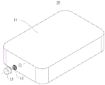
Fig. 1 is a schematic view of an exploded structure of a battery provided in some embodiments of the present application;
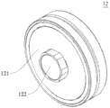
fig. 2 is a schematic perspective view of a pressure release mechanism according to some embodiments of the present disclosure;
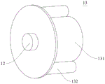
fig. 3 is a schematic structural diagram of connection between a first negative pressure mechanism and a pressure release mechanism according to some embodiments of the present disclosure;
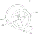
fig. 4 is a schematic perspective view of a first negative pressure mechanism according to some embodiments of the present disclosure;
fig. 5 is a schematic perspective view of an energy storage device according to some embodiments of the present disclosure;
FIG. 6 is a schematic perspective view of an energy storage device according to other embodiments of the present disclosure;
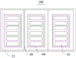
fig. 7 is a schematic front view of an energy storage device according to still other embodiments of the present disclosure;
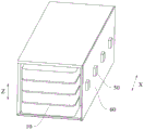
fig. 8 is a schematic perspective view of a battery cluster according to some embodiments of the present disclosure.
Icon: 10-battery; 11-a battery box; 12-a pressure release mechanism; 121-a valve body; 122-valve core; 13-a first negative pressure mechanism; 131-a negative pressure fan; 1311-a frame; 1312-fan blades; 132-a condenser tube; 1321-an inlet end; 1322-outlet end; 100-an energy storage device; 20-an energy storage box body; 21-a cabin; 22-cabin door; 30-a separator; 40-a second negative pressure mechanism; 50-a third negative pressure mechanism; 60-a battery cluster box body; z-a first direction; x-second direction.
Detailed Description
For the purposes of making the objects, technical solutions and advantages of the embodiments of the present application more apparent, the technical solutions in the embodiments of the present application will be clearly described below with reference to the drawings in the embodiments of the present application, and it is apparent that the described embodiments are some embodiments of the present application, but not all embodiments. All other embodiments, which can be made by one of ordinary skill in the art based on the embodiments herein without making any inventive effort, are intended to be within the scope of the present application.
Unless defined otherwise, all technical and scientific terms used herein have the same meaning as commonly understood by one of ordinary skill in the art to which this application belongs; the terminology used in the description of the application herein is for the purpose of describing particular embodiments only and is not intended to be limiting of the application; the terms "comprising" and "having" and any variations thereof in the description and claims of the present application and in the description of the figures above are intended to cover non-exclusive inclusions. The terms first, second and the like in the description and in the claims or in the above-described figures, are used for distinguishing between different objects and not necessarily for describing a particular sequential or chronological order.
Reference in the specification to "an embodiment" means that a particular feature, structure, or characteristic described in connection with the embodiment may be included in at least one embodiment of the application. The appearances of such phrases in various places in the specification are not necessarily all referring to the same embodiment, nor are separate or alternative embodiments mutually exclusive of other embodiments.
In the description of the present application, it should be noted that, unless explicitly specified and limited otherwise, the terms "mounted," "connected," and "attached" are to be construed broadly, and may be, for example, fixedly connected, detachably connected, or integrally connected; can be directly connected or indirectly connected through an intermediate medium, and can be communication between two elements. The specific meaning of the terms in this application will be understood by those of ordinary skill in the art as the case may be.
The term "and/or" in this application is merely an association relation describing an associated object, and indicates that three relations may exist, for example, a and/or B may indicate: a exists alone, A and B exist together, and B exists alone. In this application, the character "/" generally indicates that the associated object is an or relationship.
In the embodiments of the present application, the same reference numerals denote the same components, and in the interest of brevity, detailed descriptions of the same components are omitted in different embodiments. It should be understood that the thickness, length, width, etc. dimensions of the various components in the embodiments of the present application, as well as the overall thickness, length, width, etc. dimensions of the integrated device, are illustrative only and should not be construed as limiting the present application in any way.
The term "plurality" as used herein refers to more than two (including two).
In the present application, the battery cell may include a lithium ion secondary battery, a lithium ion primary battery, a lithium sulfur battery, a sodium lithium ion battery, a sodium ion battery, a magnesium ion battery, or the like, which is not limited by the embodiment of the present application. The battery cells may be cylindrical, flat, rectangular, or otherwise shaped, as well as the embodiments herein are not limited in this regard. The battery cells are generally classified into three types according to the packaging method: the cylindrical battery cell, the square battery cell and the soft pack battery cell are not limited thereto.
Reference to a battery in embodiments of the present application refers to a single physical module that includes one or more battery cells to provide higher voltage and capacity. For example, the battery referred to in the present application may include a battery module or a battery pack, or the like. The battery generally includes a case for enclosing one or more battery cells. The case body can prevent liquid or other foreign matters from affecting the charge or discharge of the battery cells.
The battery cell comprises an electrode assembly and electrolyte, wherein the electrode assembly consists of a positive plate, a negative plate and a separation membrane. The battery cell mainly relies on metal ions to move between the positive and negative electrode plates to operate. The positive plate comprises a positive electrode current collector and a positive electrode active material layer, wherein the positive electrode active material layer is coated on the surface of the positive electrode current collector, the positive electrode current collector without the positive electrode active material layer protrudes out of the positive electrode current collector coated with the positive electrode active material layer, and the positive electrode current collector without the positive electrode active material layer is used as a positive electrode lug. Taking a lithium ion battery as an example, the material of the positive electrode current collector may be aluminum, and the positive electrode active material may be lithium cobaltate, lithium iron phosphate, ternary lithium, lithium manganate or the like. The negative electrode sheet comprises a negative electrode current collector and a negative electrode active material layer, wherein the negative electrode active material layer is coated on the surface of the negative electrode current collector, the negative electrode current collector without the negative electrode active material layer protrudes out of the negative electrode current collector coated with the negative electrode active material layer, and the negative electrode current collector without the negative electrode active material layer is used as a negative electrode tab. The material of the negative electrode current collector may be copper, and the negative electrode active material may be carbon, silicon, or the like. In order to ensure that the high current is passed without fusing, the number of positive electrode lugs is multiple and stacked together, and the number of negative electrode lugs is multiple and stacked together. The material of the separator may be PP (polypropylene) or PE (polyethylene). In addition, the electrode assembly may be a wound structure or a lamination structure, and the embodiment of the present application is not limited thereto.
Thermal runaway of the battery is a serious safety accident, which can cause the battery to fire or even explode, directly threatening the safety of users.
In the actual use process of the battery, the battery can be influenced by various complex use environments, and potential accident hazards exist. If the pressure inside the battery is higher than the external pressure due to the conditions of overcharge, short circuit, high temperature, collision deformation and the like of the battery, the pressure inside the battery is not released in time by the pressure release mechanism of the battery, and the battery is caused to be in thermal runaway, so that the battery burns or explodes.
Based on the above considerations, embodiments of the present application provide a battery, where a negative pressure mechanism is disposed at a position of a pressure release mechanism of the battery. So arrange, when the pressure release mechanism of battery opens the pressure release, negative pressure mechanism can produce the negative pressure, and the gaseous removal toward pressure release mechanism department in the guide battery package, the outside of discharge battery has reduced potential accident potential, has improved the reliability of battery.
Referring to fig. 1, fig. 1 is a schematic view of an exploded structure of a battery 10 according to some embodiments of the present application.
The embodiment of the application provides a battery 10, and the battery 10 comprises a battery box 11, a pressure release mechanism 12 and a first negative pressure mechanism 13. The pressure release mechanism 12 is provided on a wall portion of the battery case 11, and the pressure release mechanism 12 is configured to release the internal pressure of the battery case 11 when the internal pressure or temperature of the battery case 11 reaches a threshold value. The first negative pressure mechanism 13 is connected to the pressure release mechanism 12, and the first negative pressure mechanism 13 is used for generating negative pressure to guide the gas in the battery box 11 to move to the pressure release mechanism 12.
The pressure release mechanism 12 may be opened in two ways to release the internal pressure of the battery case 11, i.e., the pressure release mechanism 12 may perform an action when the internal pressure of the battery 10 reaches a threshold value, forming a pressure release channel through which the internal pressure or temperature may be released. The pressure release mechanism 12 may also perform an action when the temperature of the battery 10 reaches a threshold value, forming a pressure release channel through which the internal pressure or temperature may be released.
The pressure release mechanism 12 may be disposed on the top wall of the battery case 11, and the pressure release mechanism 12 may be disposed on the side wall of the battery case 11.
The first negative pressure mechanism 13 can form negative pressure, the instantaneous air pressure in the area with negative pressure is smaller than the air pressure in the battery box 11, and under the action of the atmospheric pressure, air flow flowing from the high pressure area to the negative pressure area is formed, and the air flow drives the air in the battery box 11 to move to the pressure release mechanism 12.
In this embodiment, the first negative pressure mechanism 13 can generate negative pressure when the battery 10 is depressurized, so that the air pressure in the negative pressure area is lower than the air pressure in the battery 10, an air flow flowing from the high pressure area to the low pressure area is formed, the air flow drives the air in the battery box 11 to move towards the pressure release mechanism 12, the speed of moving the air in the battery box 11 towards the pressure release mechanism 12 is accelerated, the pressure release speed of the pressure release mechanism 12 is accelerated, the air in the battery 10 is discharged out of the battery box 11, potential accident potential is reduced, and the reliability of the battery 10 is improved.
In some embodiments, referring to fig. 2 and 3, fig. 2 is a schematic perspective view of a pressure relief mechanism 12 provided in some embodiments of the present application; fig. 3 is a schematic structural diagram of connection between the first negative pressure mechanism 13 and the pressure release mechanism 12 according to some embodiments of the present application. The pressure release mechanism 12 comprises a valve body 121 and a valve core 122, the valve body 121 is connected to the wall part of the battery box 11, the valve body 121 is provided with a pressure release channel, the valve core 122 is used for closing or opening the pressure release channel, and the first negative pressure mechanism 13 is connected to the valve body 121.
Specifically, the wall portion of the battery case 11 may be provided with a mounting hole to which the valve body 121 is mounted.
The pressure release passage is a passage formed in the valve body 121 and capable of communicating with the inside of the battery case 11. The valve spool 122 may open the relief passage when the temperature or pressure inside the battery 10 reaches a threshold value and close the relief passage when the temperature or pressure inside the battery 10 is below the threshold value.
Of course, in other embodiments, the pressure relief mechanism 12 may take the form of, for example, a gas valve, a pressure relief valve, or a safety valve, and may specifically take the form of a pressure-sensitive or temperature-sensitive element or structure, i.e., when the internal pressure or temperature of the battery 10 reaches a threshold value, the pressure relief mechanism 12 performs an action, thereby forming a pressure relief channel through which the internal pressure or temperature may be relieved.
In some embodiments, referring to fig. 4, fig. 4 is a schematic perspective view of a first negative pressure mechanism 13 provided in some embodiments of the present application, where the first negative pressure mechanism 13 includes a negative pressure fan 131, the negative pressure fan 131 is used for generating negative pressure, and when the pressure release mechanism 12 releases pressure, gas in the battery box 11 is guided to move towards the pressure release mechanism 12.
Alternatively, the first negative pressure mechanism 13 may also be a micro vacuum pump or the like.
In some embodiments, the first negative pressure mechanism 13 further comprises a condenser tube 132.
Specifically, the condensing medium circulates inside the condensing tube 132, the condensing tube 132 performs condensation or backflow, the condensing medium inside the condensing tube 132 can exchange heat with external gas, and the temperature of surrounding gas is reduced, so that the surrounding gas pressure is reduced. The inlet end 1321 and the outlet end 1322 of the condensation pipe 132 are respectively communicated with an external generating device to realize circulation refrigeration.
The condensing medium may be one of a gaseous condensing medium, a liquid condensing medium, and a solid condensing medium.
The gaseous condensing medium may be air. The liquid condensing medium may be water, brine, or the like. The solid condensing medium may be ice, dry ice, or the like.
The condensation pipe 132 is used for continuously refrigerating to reduce the ambient air pressure, so that the moving speed of the air in the battery box 11 to the pressure relief mechanism 12 can be further increased, the potential accident potential is further reduced, and the reliability of the battery 10 is improved.
In some embodiments, the first negative pressure mechanism 13 may include both a negative pressure fan 131 and a condenser tube 132, where the negative pressure fan 131 includes a frame 1311 and a fan 1312, and the fan 1312 is rotatably disposed in the frame 1311, and the condenser tube 132 is wound around the frame 1311.
The frame 1311 may be connected to the valve body 121 of the pressure relief mechanism 12, and the condensation duct 132 may be wound around the outer circumference of the frame 1311.
The condensing duct 132 may be wound a half turn, one turn, or more than one turn around the outer circumference of the frame 1311. Illustratively, in fig. 4, the condenser tube 132 is wrapped around the exterior Zhou Chan of the frame 1311.
Further, the condenser tube 132 may be disposed on a side of the frame 1311 adjacent to the pressure relief mechanism 12.
On the basis of the negative pressure fan 131, the condenser tube 132 is wound around the frame 1311, and continuously refrigerates around the frame 1311, so as to reduce the ambient air pressure, and accelerate the movement of the air in the battery 10 to the pressure release mechanism 12 when the pressure release mechanism 12 releases the pressure.
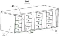
The present disclosure further provides an energy storage device 100, and referring to fig. 5, fig. 5 is a schematic perspective view of the energy storage device 100 according to some embodiments of the present disclosure.
The energy storage device 100 includes an energy storage case 20 and the battery 10 provided in any of the above embodiments, and the battery 10 is accommodated in the energy storage case 20.
Typically, the interior of the energy storage device 100 is a relatively sealed structure (not completely sealed). The internal energy storage of the energy storage device 100 typically employs a battery 10 of LFP (LiFePO 4, lithium iron phosphate) system. The battery 10 of the LFP system has the following accident potential: on the one hand, opening the valve of the pressure release mechanism 12 of the battery 10 generates a large amount of combustible substances, such as electrolyte vapors. On the other hand, if a certain cell 10 in the energy storage device 100 is out of control, a large amount of combustible materials such as H are generated 2 、CO、CH 4 、C 2 H 6 Etc.
The generation of the combustible material is accompanied by high temperature, so that the pressure in the battery 10 is increased, if the combustible material stays in the energy storage device 100, the explosion can occur due to insufficient strength of the energy storage box 20, the high temperature and high pressure gas can impact the surrounding battery 10, the combustible material is easy to burn when encountering sparks, the explosion is caused, secondary hazard is caused, and accident potential exists.
With the foregoing in mind, referring to fig. 5, an embodiment of the present application provides an energy storage device 100, where the energy storage device 100 further includes a second negative pressure mechanism 40, and the second negative pressure mechanism 40 is configured to generate a negative pressure to guide the gas in the energy storage tank 20 to be exhausted.
The second negative pressure mechanism 40 may include a frame 1311 and a fan 1312, the frame 1311 being installed at a wall of the energy storage tank 20, the fan 1312 rotating to form a negative pressure. The instantaneous air pressure of the region where the negative pressure exists is smaller than the air pressure inside the energy storage tank 20, and under the action of the atmospheric pressure, the inside of the energy storage device 100 forms an air flow which directionally flows from the high pressure region to the negative pressure region, thereby guiding the air inside the energy storage tank 20 to be discharged.
In this embodiment, the second negative pressure mechanism 40 can generate negative pressure, and the inside of the energy storage tank 20 forms an air flow flowing from the high pressure region to the low pressure region, so as to discharge the high temperature and high pressure gas inside the battery 10 out of the energy storage tank 20.
If the combustible concentration in a local area inside the energy storage tank 20 is too high or the gas temperature in the local area is too high, thermal runaway or even explosion of the battery 10 is caused, and accident risks exist. Therefore, the second negative pressure mechanism 40 is arranged to exhaust the gas in the energy storage box 20, so that the concentration of combustible materials in each area in the energy storage box 20 can be balanced, the pressure difference between the inside and the outside of the energy storage device 100 can be reduced, and the potential accident potential of the energy storage device 100 can be reduced.
In some embodiments, referring to fig. 6, fig. 6 is a schematic perspective view of an energy storage device 100 according to other embodiments of the present application. The energy storage tank 20 includes a tank body 21 and a door 22, the tank body 21 having an opening, the door 22 closing the opening.
The compartment 21 is for accommodating the battery 10, and the door 22 is for opening or closing the opening of the door 22.
The second negative pressure mechanism 40 may be disposed on the cabin 21, the second negative pressure mechanism 40 may be disposed on the cabin door 22, or both the cabin 21 and the cabin door 22 may be disposed with the second negative pressure mechanism 40.
The second negative pressure mechanism 40 is arranged on the cabin 21 or the cabin door 22, so that the internal space of the energy storage box 20 is not occupied, and a pipeline or other structures for guiding the gas to be discharged are not required to be arranged in the energy storage box 20. Under the action of atmospheric pressure, the gas in the energy storage box body 20 flows to the second negative pressure mechanism 40 to form directional and stable air flow, and the gas is discharged, so that potential accident potential is reduced.
In addition, the cabin door 22 belongs to a door leaf for opening the energy storage device 100, and the second negative pressure mechanism 40 is arranged on the cabin door 22, so that an operator can conveniently detach and install the second negative pressure mechanism 40.
In some embodiments, referring to fig. 5, a partition plate 30 is disposed inside the energy storage tank 20, the partition plate 30 divides the internal space of the energy storage tank 20 into a plurality of battery bins, a second negative pressure mechanism 40 is disposed on the partition plate 30, an exhaust port is disposed on a wall portion of the energy storage tank 20, and a channel communicating the second negative pressure mechanism 40 and the exhaust port is disposed in the partition plate 30.
The wall of the energy storage tank 20 may be a cabin 21, and the wall of the energy storage tank 20 may be a cabin door 22. That is, the exhaust port may be provided in the cabin 21 or in the door 22.
A channel which is communicated with the second negative pressure mechanism 40 and the exhaust port is arranged in the partition plate 30, and the gas in the energy storage box body 20 can be exhausted after reaching the exhaust port from the channel through the second negative pressure mechanism 40.
The baffle 30 is located in the energy storage box 20, no rainwater exists in the energy storage box 20, the energy storage box 20 is not affected by external environment, the internal environment of the energy storage box 20 is relatively stable, and compared with the embodiment that the second negative pressure mechanism 40 is arranged in the cabin door 22, the second negative pressure mechanism 40 is arranged in the baffle 30, so that the service life of the second negative pressure mechanism 40 can be prolonged.
Further, an operator can set the exhaust port at a position far away from the high-voltage line according to the arrangement condition of the wire harness inside the energy storage device 100, so as to reduce potential accident potential.
In some embodiments, referring to fig. 7 and 8, fig. 7 is a schematic front view of an energy storage device 100 according to other embodiments of the present application; fig. 8 is a schematic perspective view of a battery cluster according to some embodiments of the present disclosure. The energy storage device 100 includes a plurality of battery clusters, each of which includes a battery cluster housing 60 and a plurality of batteries 10 disposed in the battery cluster housing 60, and a third negative pressure mechanism 50 disposed at a wall portion of the battery cluster housing 60, the third negative pressure mechanism 50 for generating negative pressure to balance an internal pressure and an external pressure of the battery cluster housing 60.
The third negative pressure mechanism 50 may also include a frame 1311 and fan blades 1312, and the frame 1311 may be disposed on a side wall of the battery pack case 60.
Since the second negative pressure mechanism 40 is disposed in the energy storage box 20 and is far away from the battery 10, if the pressure in the area is not timely reduced when one of the batteries 10 discharges high temperature or is affected by combustible substances, the gas impacts the surrounding battery 10, which may cause secondary danger.
Therefore, the third negative pressure mechanism 50 is configured to balance the internal pressure and the external pressure of the battery cluster housing 60 in time, and to discharge the high temperature, high pressure and combustible gas in the battery cluster out of the battery cluster, so as to maintain a relatively stable internal environment for the battery cluster, thereby further reducing the potential accident potential of the energy storage device 100.
In some embodiments, the plurality of batteries 10 in the battery cluster housing 60 are arranged along the first direction Z, and the plurality of third negative pressure mechanisms 50 arranged along the second direction X, which is perpendicular to the first direction Z, are disposed on each battery cluster housing 60.
Illustratively, in fig. 8, the height direction is defined as a first direction Z, and a plurality of cells 10 are arranged in the height direction.
The number of the third negative pressure mechanisms 50 may be one, two, three, or the like. Illustratively, in fig. 8, the number of third negative pressure mechanisms 50 is four.
Compared with the energy storage box 20, the battery cluster box 60 is close to the battery 10, the third negative pressure mechanisms 50 are arranged on the wall parts of the battery cluster box 60, if one battery 10 generates high temperature, high pressure or combustible gas, the plurality of third negative pressure mechanisms 50 can generate negative pressure in the area close to the battery 10 in time, the gas can be discharged in time, the internal pressure and the external pressure of the battery cluster box 60 are balanced, and potential accident potential is reduced.
In some embodiments, the energy storage device 100 further includes a battery management system to which the first negative pressure mechanism 13 is connected.
The battery management system is used for intelligently managing and maintaining each battery 10, preventing the battery 10 from being overcharged and overdischarged, prolonging the service life of the battery 10, monitoring the state of the battery 10 and reducing potential accident potential.
The battery management system is connected to the first negative pressure mechanism 13 to intelligently manage and control the first negative pressure mechanism 13.
Of course, in other embodiments, the battery management system may also connect the second negative pressure mechanism 40 and the third negative pressure mechanism 50 at the same time.
In some embodiments, the present application provides an energy storage device 100, the energy storage device 100 comprising a battery cluster housing 60, an energy storage housing 20, a second negative pressure mechanism 40, a third negative pressure mechanism 50, and a plurality of batteries 10. The battery 10 comprises a battery box 11, a pressure release mechanism 12 and a first negative pressure mechanism 13, wherein the pressure release mechanism 12 is arranged on the wall part of the battery box 11, the pressure release mechanism 12 is used for releasing the internal pressure of the battery box 11 when the internal pressure or temperature of the battery box 11 reaches a threshold value, the first negative pressure mechanism 13 is connected to the pressure release mechanism 12, and the first negative pressure mechanism 13 is used for generating negative pressure so as to guide gas in the battery box 11 to move towards the pressure release mechanism 12. The second negative pressure mechanism 40 is disposed on the energy storage tank 20, and the second negative pressure mechanism 40 is used for generating negative pressure to guide the gas in the energy storage tank 20 to be discharged. The battery cluster box 60 is provided with a plurality of batteries 10 therein, the third negative pressure mechanism 50 is disposed on a wall portion of the battery cluster box 60, and the third negative pressure mechanism 50 is used for generating negative pressure to balance the internal pressure and the external pressure of the battery cluster box 60.
It should be noted that, in the case of no conflict, the embodiments and features in the embodiments may be combined with each other.
The above embodiments are only for illustrating the technical solution of the present application, and are not intended to limit the present application, and various modifications and changes may be made to the present application by those skilled in the art. Any modification, equivalent replacement, improvement, etc. made within the spirit and principles of the present application should be included in the protection scope of the present application.
Claims (12)
1. A battery, comprising:
a battery case;
the pressure release mechanism is arranged on the wall part of the battery box body and is used for releasing the internal pressure of the battery box body when the internal pressure or the temperature of the battery box body reaches a threshold value;
the first negative pressure mechanism is connected to the pressure release mechanism and used for generating negative pressure so as to guide the gas in the battery box body to move towards the pressure release mechanism.
2. The battery of claim 1, wherein the pressure relief mechanism comprises a valve body and a valve core, the valve body is connected to a wall portion of the battery box body, the valve body has a pressure relief channel, the valve core is used for closing or opening the pressure relief channel, and the first negative pressure mechanism is connected to the valve body.
3. The battery of claim 1, wherein the first negative pressure mechanism comprises a negative pressure fan.
4. The battery of claim 1, wherein the first negative pressure mechanism comprises a condenser tube.
5. The battery of claim 1, wherein the first negative pressure mechanism comprises a negative pressure fan and a condenser tube, the negative pressure fan comprising a frame and a fan blade, the fan blade rotatably disposed within the frame, the condenser tube wound around the frame.
6. An energy storage device, comprising:
an energy storage tank;
the battery of any one of claims 1-5, the battery being housed within the energy storage housing.
7. The energy storage device of claim 6, further comprising a second negative pressure mechanism for generating a negative pressure to direct the discharge of gas within the energy storage tank.
8. The energy storage device according to claim 7, characterized in that the energy storage tank comprises a cabin body having an opening and a door for closing the opening, the second negative pressure mechanism being provided at the cabin body and/or the door.
9. The energy storage device according to claim 7, wherein a partition plate is provided inside the energy storage box body, the partition plate divides an inner space of the energy storage box body into a plurality of battery bins, the second negative pressure mechanism is provided in the partition plate, an exhaust port is provided in a wall portion of the energy storage box body, and a channel communicating the second negative pressure mechanism and the exhaust port is provided in the partition plate.
10. The energy storage device of claim 6, wherein the energy storage device comprises a plurality of battery clusters, each of the battery clusters comprising a battery cluster housing and a plurality of the batteries disposed within the battery cluster housing, and a third negative pressure mechanism disposed at a wall portion of the battery cluster housing for generating a negative pressure to balance an internal pressure and an external pressure of the battery cluster housing.
11. The energy storage device of claim 10, wherein a plurality of said cells in said battery cluster housing are arranged in a first direction, and a plurality of said third negative pressure mechanisms are disposed on each of said battery cluster housing and arranged in a second direction, said second direction being perpendicular to said first direction.
12. The energy storage device of claim 6, further comprising a battery management system, wherein said first negative pressure mechanism is connected to said battery management system.
Priority Applications (1)
| Application Number | Priority Date | Filing Date | Title |
|---|---|---|---|
| CN202320448498.2U CN219226532U (en) | 2023-03-10 | 2023-03-10 | Battery and energy storage device |
Applications Claiming Priority (1)
| Application Number | Priority Date | Filing Date | Title |
|---|---|---|---|
| CN202320448498.2U CN219226532U (en) | 2023-03-10 | 2023-03-10 | Battery and energy storage device |
Publications (1)
| Publication Number | Publication Date |
|---|---|
| CN219226532U true CN219226532U (en) | 2023-06-20 |
Family
ID=86739572
Family Applications (1)
| Application Number | Title | Priority Date | Filing Date |
|---|---|---|---|
| CN202320448498.2U Active CN219226532U (en) | 2023-03-10 | 2023-03-10 | Battery and energy storage device |
Country Status (1)
| Country | Link |
|---|---|
| CN (1) | CN219226532U (en) |
-
2023
- 2023-03-10 CN CN202320448498.2U patent/CN219226532U/en active Active
Similar Documents
| Publication | Publication Date | Title |
|---|---|---|
| CN114175363B (en) | Battery and related device, preparation method and preparation equipment thereof | |
| EP1806807B1 (en) | Medium- or large-sized battery pack having safety device | |
| US11342611B2 (en) | Battery pack, vehicle and control method for alleviating thermal runaway spreading of battery pack | |
| CN112018301B (en) | Battery, electric equipment, method and equipment for preparing battery | |
| CN112018302B (en) | Battery, electric device, method and equipment for preparing battery | |
| CN112018300B (en) | Battery box, battery, electric device, and method and device for preparing battery | |
| CN213636145U (en) | Battery, device comprising battery and equipment for preparing battery | |
| CN114175365B (en) | Battery and related device, preparation method and preparation equipment thereof | |
| WO2024077789A1 (en) | Battery and electric device | |
| CN216288850U (en) | Battery cell, battery and power consumption device | |
| CN112018322B (en) | Battery box, battery, electric device, and method and device for preparing battery | |
| WO2022104539A1 (en) | Fire prevention device, box assembly, battery, electric device, and method for producing battery | |
| CN219226532U (en) | Battery and energy storage device | |
| JP2023544047A (en) | Battery housing, battery, power consumption device, battery manufacturing method and device | |
| WO2022082393A1 (en) | Box body for battery, battery, electric apparatus, and battery manufacturing method and device | |
| CN220155580U (en) | Battery and electric equipment | |
| KR20220102642A (en) | Batteries and related devices, manufacturing methods and manufacturing devices | |
| WO2023159847A1 (en) | Battery cell, battery, and electrical apparatus | |
| WO2023141878A1 (en) | Battery, electric apparatus, and battery manufacturing method and manufacturing device | |
| CN216213826U (en) | Split type explosion-proof lithium cell group | |
| KR102590339B1 (en) | Battery box body, battery, electrical device, battery manufacturing method and device | |
| WO2023004726A1 (en) | Battery box, battery, electrical device, battery manufacturing method, and device | |
| JP2023528296A (en) | BATTERY, POWER CONSUMER, METHOD AND APPARATUS FOR BATTERY MANUFACTURE | |
| CN219180610U (en) | Energy storage device | |
| CN218939874U (en) | Battery and electricity utilization device |
Legal Events
| Date | Code | Title | Description |
|---|---|---|---|
| GR01 | Patent grant | ||
| GR01 | Patent grant |