CN219224363U - Pressure testing machine - Google Patents
Pressure testing machine Download PDFInfo
- Publication number
- CN219224363U CN219224363U CN202223481685.5U CN202223481685U CN219224363U CN 219224363 U CN219224363 U CN 219224363U CN 202223481685 U CN202223481685 U CN 202223481685U CN 219224363 U CN219224363 U CN 219224363U
- Authority
- CN
- China
- Prior art keywords
- workbench
- plate
- workstation
- testing machine
- pressure testing
- Prior art date
- Legal status (The legal status is an assumption and is not a legal conclusion. Google has not performed a legal analysis and makes no representation as to the accuracy of the status listed.)
- Active
Links
Images


Classifications
-
- Y—GENERAL TAGGING OF NEW TECHNOLOGICAL DEVELOPMENTS; GENERAL TAGGING OF CROSS-SECTIONAL TECHNOLOGIES SPANNING OVER SEVERAL SECTIONS OF THE IPC; TECHNICAL SUBJECTS COVERED BY FORMER USPC CROSS-REFERENCE ART COLLECTIONS [XRACs] AND DIGESTS
- Y02—TECHNOLOGIES OR APPLICATIONS FOR MITIGATION OR ADAPTATION AGAINST CLIMATE CHANGE
- Y02E—REDUCTION OF GREENHOUSE GAS [GHG] EMISSIONS, RELATED TO ENERGY GENERATION, TRANSMISSION OR DISTRIBUTION
- Y02E60/00—Enabling technologies; Technologies with a potential or indirect contribution to GHG emissions mitigation
- Y02E60/10—Energy storage using batteries
Abstract
The utility model discloses a pressure testing machine, which relates to the technical field of pressure tests and comprises a workbench; a top plate is arranged above the workbench, a hydraulic cylinder is arranged on the top plate, and a telescopic end of the hydraulic cylinder penetrates through the top plate and is connected with a pressing plate; the screw rod is installed to the both sides of workstation all rotate, the motor is installed to the tip of workstation, and the drive shaft and the screw transmission of motor are connected, two equal thread bush is equipped with the cover piece on the screw rod, cover piece and workstation lateral wall sliding butt, a pair of cover piece upper surface is all vertical to be fixed with the mounting panel, a pair of be connected with the scraper blade between the mounting panel, the both ends of workstation all are provided with the collection box. The utility model has reasonable structure, can realize the effect of quickly cleaning the concrete fragments on the workbench on the premise of ensuring the integrity of the workbench and providing stable support for the pressure test of the concrete blocks, creates favorable conditions for continuous test, ensures the validity of test results and improves the test efficiency.
Description
Technical Field
The utility model relates to the technical field of pressure tests, in particular to a pressure testing machine.
Background
In the construction engineering, the performance of concrete is usually tested at regular time, by casting a batch of square concrete test blocks with specified size, and extruding the concrete test blocks by a pressure tester until the test blocks are broken, so as to obtain each data value.
The utility model provides an utility model patent of 202220896562.2 discloses a pressure testing machine, including the base case, the equal fixedly connected with bracing piece in upper side wall four corners department of base case, four the same mounting panel of upper end fixedly connected with of bracing piece, the lateral wall fixedly connected with pneumatic cylinder of mounting panel, the output of pneumatic cylinder runs through the lateral wall and the fixedly connected with clamp plate of mounting panel, the upper side wall fixedly connected with brace table of base case, a plurality of waste material mouths have been seted up to the upper side wall of base case, socket and pegging graft have the waste material frame in the socket have been seted up to the lateral wall of base case, and this application can make things convenient for the cement incomplete piece and the grit on the operating personnel clearance test machine mesa, has improved the convenience of operating personnel work, has guaranteed the work efficiency of pressure testing machine. However, in the actual test operation process, the applicant found that since the waste port for discharging crushed concrete fragments is formed in the upper side wall of the bottom box, and the waste port is formed in a plurality of parts, the structural integrity of the bottom box is further damaged, the stability of the bottom box is reduced, and it is difficult to ensure that the bottom box can provide stable support for the pressure test of the concrete test block, and the test result is affected, therefore, the application provides a pressure testing machine to meet the requirements.
Disclosure of Invention
The utility model aims at providing a pressure testing machine, under the integrality of assurance workstation, can provide stable support's the pressure test to the concrete piece under, realize the effect to the quick clearance of concrete fragment on the workstation, create the advantage for continuous test, both ensured the validity of test result, improved test efficiency again.
In order to achieve the above purpose, the present application provides the following technical solutions: a pressure testing machine comprises a workbench;
a top plate is arranged above the workbench, a hydraulic cylinder is arranged on the top plate, and a telescopic end of the hydraulic cylinder penetrates through the top plate and is connected with a pressing plate;
the screw rod is installed to the both sides of workstation all rotate, the motor is installed to the tip of workstation, and the drive shaft and the screw transmission of motor are connected, two equal thread bush is equipped with the cover piece on the screw rod, cover piece and workstation lateral wall sliding butt, a pair of cover piece upper surface is all vertical to be fixed with the mounting panel, a pair of be connected with the scraper blade between the mounting panel, the both ends of workstation all are provided with the collection box.
Preferably, fixed blocks are fixed on the side wall of the workbench at positions close to the end parts, the screw rod is rotatably arranged between the pair of fixed blocks, and the motor is arranged on one of the fixed blocks.
Preferably, the scraping strip is embedded at the bottom of the scraping plate, and the bottom end of the scraping strip is in sliding abutting connection with the upper surface of the workbench.
Preferably, a cavity for embedding the scraping strip is formed in the scraping plate, and a compression spring is vertically arranged between the scraping strip and the top wall of the cavity.
Preferably, the side walls of the top plate along the width direction of the workbench are vertically provided with side plates, and the bottom ends of the side plates are connected with the bottom of the workbench.
Preferably, the two sides of the side plate are both fixed with a first baffle, and the scraper can translate between the first baffle and the workbench.
Preferably, a second baffle is arranged between the two ends of the first baffle, which are positioned on the same side of the side plate, and the top of the second baffle is rotationally connected with the first baffle.
In summary, the utility model has the technical effects and advantages that:
1. the utility model has reasonable structure, the scraper is arranged on the upper surface of the workbench, after the concrete test block is crushed, the motor is only required to be started to drive the screw rod to rotate, the sleeve block is utilized to drive the scraper to move from one end of the workbench to the other end, the concrete fragments on the workbench can be pushed into the corresponding collecting boxes, no manual cleaning of operators is needed, and favorable conditions are created for continuous test.
2. According to the utility model, the scraping strip is embedded at the bottom of the scraping plate, and the elastic force of the compression spring pushes the scraping strip to elastically abut against the upper surface of the workbench when the scraping plate moves to clean the surface of the workbench, so that the cleaning effect of concrete fragments is improved under the condition that the scraping plate can smoothly translate.
3. According to the utility model, the rectangular frame body formed by the side plates, the first baffle plate and the second baffle plate can play a role in protection in the pressure test process, so that the problem that the concrete test block is crushed and then bursts to the periphery to cause injury to operators can be avoided as much as possible, and the second baffle plate is rotatably arranged, so that the concrete test block can be taken and placed conveniently.
Drawings
In order to more clearly illustrate the embodiments of the present application or the technical solutions in the prior art, the drawings that are required in the embodiments or the description of the prior art will be briefly described below, it being obvious that the drawings in the following description are only some embodiments of the present application, and that other drawings may be obtained according to these drawings without inventive effort for a person skilled in the art.
FIG. 1 is a schematic diagram of the overall structure of the present utility model;
FIG. 2 is a schematic view of a workbench according to the present utility model;
FIG. 3 is a schematic view of a screed according to the present utility model;
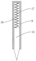
FIG. 4 is a schematic view of the internal structure of the scraper of the present utility model;
fig. 5 is a schematic view of the top plate structure of the present utility model.
In the figure: 1. a work table; 2. a top plate; 3. a hydraulic cylinder; 4. a pressing plate; 5. a side plate; 6. a first baffle; 7. a second baffle; 8. a collection box; 9. a scraper; 10. a fixed block; 11. a screw rod; 12. a motor; 13. sleeving blocks; 14. a mounting plate; 15. scraping the strip; 16. a cavity; 17. compressing the spring.
Detailed Description
The following description of the embodiments of the present utility model will be made clearly and completely with reference to the accompanying drawings, in which it is apparent that the embodiments described are only some embodiments of the present utility model, but not all embodiments. All other embodiments, which can be made by those skilled in the art based on the embodiments of the utility model without making any inventive effort, are intended to be within the scope of the utility model.
Examples: referring to fig. 1 to 5, a pressure testing machine includes a table 1; the top plate 2 is arranged above the workbench 1, the hydraulic cylinder 3 is arranged on the top plate 2, the telescopic end of the hydraulic cylinder 3 penetrates through the top plate 2 and is connected with the pressing plate 4, a concrete test block is placed on the workbench 1 to be aligned with the pressing plate 4, the hydraulic cylinder 3 is started to push the pressing plate 4 to press down, the concrete test block is extruded and crushed, pressure data of the concrete test block are obtained, and then a pressure test of concrete can be realized.
In this embodiment, the lateral walls of the top plate 2 along the width direction of the workbench 1 are vertically provided with side plates 5, and the bottom ends of the side plates 5 are connected with the bottom of the workbench 1 for providing stable support for the top plate 2. Further, the two sides of the side plate 5 are both fixed with first baffle plates 6, a second baffle plate 7 is arranged between the end parts of the two first baffle plates 6 positioned on the same side of the side plate 5, and the top of the second baffle plate 7 is rotationally connected with the first baffle plates 6. Through this technical scheme, the rectangle framework that curb plate 5, first baffle 6 and second baffle 7 formed can play the effect of protection in pressure test process, can avoid the concrete test block to the problem that the injection caused the injury to operating personnel all around after being crushed as far as possible, and wherein the rotation installation of second baffle 7 can be convenient for get of concrete test block put.
As a preferred implementation manner in the embodiment, screw rods 11 are rotatably installed on two sides of the workbench 1, a motor 12 is installed at the end part of the workbench 1, a driving shaft of the motor 12 is in transmission connection with the screw rods 11, sleeve blocks 13 are sleeved on the two screw rods 11 in a threaded manner, the sleeve blocks 13 are in sliding abutting connection with the side wall of the workbench 1, and the motor 12 is started to drive the screw rods 11 to rotate so as to drive the sleeve blocks 13 to move along the length direction of the side wall of the workbench 1. The upper surfaces of the pair of sleeve blocks 13 are vertically fixed with mounting plates 14, a scraping plate 9 is connected between the pair of mounting plates 14, and the scraping plate 9 can be horizontally moved between the first baffle 6 and the workbench 1. Both ends of the workbench 1 are provided with collecting boxes 8. Through this technical scheme, after the concrete test block crushing, only need start motor 12 drive lead screw 11 rotatory, utilize cover piece 13 to drive scraper blade 9 and remove from the one end of workstation 1 towards other one end, can push away the concrete fragment on the workstation 1 to corresponding collection box 8 in, need not the manual clearance of operating personnel, create the advantage for continuous test, and because collection box 8 sets up at the both ends of workstation 1, and then the integrality of workstation 1 has been guaranteed to this structure, make workstation 1 can provide stable support to the pressure test of concrete block, both ensured the validity of test result, improved test efficiency again.
In this embodiment, fixed blocks 10 are fixed to the side walls of the table 1 at positions near the ends, a screw 11 is rotatably mounted between a pair of the fixed blocks 10, and a motor 12 is mounted on one of the fixed blocks 10, so that the screw 11 and the motor 12 are mounted.
In a further embodiment, the bottom of the scraping plate 9 is embedded with the scraping strip 15, the bottom end of the scraping strip 15 is in sliding butt with the upper surface of the workbench 1, specifically, a cavity 16 in which the scraping strip 15 is embedded is formed in the scraping plate 9, the scraping strip 15 can be movably embedded into the cavity 16, a compression spring 17 is vertically arranged between the scraping strip 15 and the top wall of the cavity 16, when the scraping plate 9 moves to clean the surface of the workbench 1, the elastic force of the compression spring 17 pushes the scraping strip 15 to elastically abut against the upper surface of the workbench 1, and the cleaning effect of concrete fragments is improved under the condition that smooth translation of the scraping plate 9 is ensured.
The working principle of the utility model is as follows:
when the concrete test block pressing device is used, the concrete test block is placed on the workbench 1 to be aligned with the pressing plate 4, the hydraulic cylinder 3 is started to push the pressing plate 4 to press down, the concrete test block is extruded and crushed, pressure data of the concrete test block are obtained, a concrete pressure test is achieved, in the pressure test process, the side plate 5, the first baffle 6 and the second baffle 7 form a rectangular protection frame body, and the problem that the concrete test block is crushed and then sprayed to the periphery to cause injury to operators can be avoided as much as possible. Further, after the concrete test block is crushed, the motor 12 is started to drive the screw rod 11 to rotate, the sleeve block 13 drives the scraping plate 9 to move from one end of the workbench 1 to the other end, and then concrete fragments on the workbench 1 can be pushed into the corresponding collecting boxes 8 without manual cleaning of operators, so that favorable conditions are created for continuous test, and the test efficiency is improved. Further, in the process of moving the scraping plate 9, the elastic force of the compression spring 17 pushes the scraping bar 15 to elastically abut against the upper surface of the workbench 1, so that the cleaning effect of the concrete fragments is improved under the condition of ensuring that the scraping plate 9 can smoothly translate.
Finally, it should be noted that: the foregoing description is only illustrative of the preferred embodiments of the present utility model, and although the present utility model has been described in detail with reference to the foregoing embodiments, it will be apparent to those skilled in the art that modifications may be made to the embodiments described, or equivalents may be substituted for elements thereof, and any modifications, equivalents, improvements or changes may be made without departing from the spirit and principles of the present utility model.
Claims (7)
1. The utility model provides a pressure testing machine, includes workstation (1), its characterized in that:
a top plate (2) is arranged above the workbench (1), a hydraulic cylinder (3) is arranged on the top plate (2), and the telescopic end of the hydraulic cylinder (3) penetrates through the top plate (2) and is connected with a pressing plate (4);
screw rod (11) are all installed in the both sides of workstation (1) rotation, motor (12) are installed to the tip of workstation (1), and the drive shaft and the screw rod (11) transmission of motor (12) are connected, two equal thread bush is equipped with cover piece (13) on screw rod (11), cover piece (13) and workstation (1) lateral wall sliding butt, a pair of cover piece (13) upper surface is all vertical mounting panel (14) that is fixed with, a pair of be connected with scraper blade (9) between mounting panel (14), the both ends of workstation (1) all are provided with collection box (8).
2. A pressure testing machine according to claim 1, wherein: fixed blocks (10) are fixed at positions, close to the end parts, on the side walls of the workbench (1), the screw rods (11) are rotatably arranged between the pair of fixed blocks (10), and the motor (12) is arranged on one of the fixed blocks (10).
3. A pressure testing machine according to claim 1, wherein: the bottom of the scraping plate (9) is embedded with a scraping strip (15), and the bottom end of the scraping strip (15) is in sliding abutting connection with the upper surface of the workbench (1).
4. A pressure testing machine according to claim 3, wherein: a cavity (16) for embedding the scraping strip (15) is formed in the scraping plate (9), and a compression spring (17) is vertically arranged between the scraping strip (15) and the top wall of the cavity (16).
5. A pressure testing machine according to claim 1, wherein: the top plate (2) is vertically provided with side plates (5) along the side walls of the width direction of the workbench (1), and the bottom ends of the side plates (5) are connected with the bottom of the workbench (1).
6. A pressure testing machine according to claim 5, wherein: the two sides of the side plate (5) are both fixed with a first baffle plate (6), and a scraping plate (9) can be horizontally moved between the first baffle plate (6) and the workbench (1).
7. A pressure testing machine according to claim 6, wherein: a second baffle (7) is arranged between the end parts of the two first baffles (6) on the same side of the side plate (5), and the top of the second baffle (7) is rotationally connected with the first baffles (6).
Priority Applications (1)
| Application Number | Priority Date | Filing Date | Title |
|---|---|---|---|
| CN202223481685.5U CN219224363U (en) | 2022-12-27 | 2022-12-27 | Pressure testing machine |
Applications Claiming Priority (1)
| Application Number | Priority Date | Filing Date | Title |
|---|---|---|---|
| CN202223481685.5U CN219224363U (en) | 2022-12-27 | 2022-12-27 | Pressure testing machine |
Publications (1)
| Publication Number | Publication Date |
|---|---|
| CN219224363U true CN219224363U (en) | 2023-06-20 |
Family
ID=86733807
Family Applications (1)
| Application Number | Title | Priority Date | Filing Date |
|---|---|---|---|
| CN202223481685.5U Active CN219224363U (en) | 2022-12-27 | 2022-12-27 | Pressure testing machine |
Country Status (1)
| Country | Link |
|---|---|
| CN (1) | CN219224363U (en) |
-
2022
- 2022-12-27 CN CN202223481685.5U patent/CN219224363U/en active Active
Similar Documents
| Publication | Publication Date | Title |
|---|---|---|
| CN114839047A (en) | Withstand voltage detection device for civil engineering material experiments | |
| CN219224363U (en) | Pressure testing machine | |
| CN211306600U (en) | Cutting device is used in furniture plank production | |
| CN214136428U (en) | Two-sided planing processing equipment of bamboo chip | |
| CN215969092U (en) | Full-automatic clear waste material cross cutting equipment | |
| CN210719874U (en) | Convenient type concrete mortar trigeminy examination mould | |
| CN112497356A (en) | Be used for woodwork carving to use wire cut electrical discharge machining | |
| CN220259712U (en) | Discharging mechanism of aluminum profile cutting equipment | |
| CN219617987U (en) | Glass fiber window screening breakpoint cutting device | |
| CN220497293U (en) | Waste material compression device is used in aluminum sheet production | |
| CN212653874U (en) | Plastic insulating material apparatus for producing with dust removal function | |
| CN216607960U (en) | Center is attacked to two main shafts brill | |
| CN219255743U (en) | Multi-angle cutting positioning fixture for plates | |
| CN220611876U (en) | Stamping die convenient to clearance | |
| CN216181399U (en) | Can absorb environment-friendly oriented strand board erection equipment of formaldehyde | |
| CN216900118U (en) | Concrete impermeability instrument | |
| CN219634012U (en) | Auxiliary machining device for planing machine | |
| CN219046041U (en) | Automatic compaction instrument of drawing of patterns | |
| CN216309619U (en) | Be applied to concrete slab intensity detection device of construction engineering | |
| CN214814428U (en) | Reinforcing bar cutting is with reason material device | |
| CN219854739U (en) | Disc cutting equipment | |
| CN214349933U (en) | Aluminum pipe high efficiency cutting device for green building | |
| CN219104544U (en) | Mortar strength detection device | |
| CN215703005U (en) | Concrete slab cutting device | |
| CN220349115U (en) | Textile corner material recovery device |
Legal Events
| Date | Code | Title | Description |
|---|---|---|---|
| DD01 | Delivery of document by public notice | ||
| DD01 | Delivery of document by public notice |
Addressee: Zhang Xiaobin Document name: Notification of Qualified Procedures |
|
| DD01 | Delivery of document by public notice | ||
| DD01 | Delivery of document by public notice |
Addressee: Zhang Xiaobin Document name: Modification and Correction Notice |
|
| GR01 | Patent grant | ||
| GR01 | Patent grant |