CN219190528U - Fitment material cutting device that fitment was used - Google Patents
Fitment material cutting device that fitment was used Download PDFInfo
- Publication number
- CN219190528U CN219190528U CN202223399091.XU CN202223399091U CN219190528U CN 219190528 U CN219190528 U CN 219190528U CN 202223399091 U CN202223399091 U CN 202223399091U CN 219190528 U CN219190528 U CN 219190528U
- Authority
- CN
- China
- Prior art keywords
- fixedly connected
- finishing
- sliding
- cutting device
- material cutting
- Prior art date
- Legal status (The legal status is an assumption and is not a legal conclusion. Google has not performed a legal analysis and makes no representation as to the accuracy of the status listed.)
- Active
Links
Images

Classifications
-
- Y—GENERAL TAGGING OF NEW TECHNOLOGICAL DEVELOPMENTS; GENERAL TAGGING OF CROSS-SECTIONAL TECHNOLOGIES SPANNING OVER SEVERAL SECTIONS OF THE IPC; TECHNICAL SUBJECTS COVERED BY FORMER USPC CROSS-REFERENCE ART COLLECTIONS [XRACs] AND DIGESTS
- Y02—TECHNOLOGIES OR APPLICATIONS FOR MITIGATION OR ADAPTATION AGAINST CLIMATE CHANGE
- Y02P—CLIMATE CHANGE MITIGATION TECHNOLOGIES IN THE PRODUCTION OR PROCESSING OF GOODS
- Y02P70/00—Climate change mitigation technologies in the production process for final industrial or consumer products
- Y02P70/10—Greenhouse gas [GHG] capture, material saving, heat recovery or other energy efficient measures, e.g. motor control, characterised by manufacturing processes, e.g. for rolling metal or metal working
Abstract
The utility model discloses a decoration material cutting device for decoration, which comprises a workbench, wherein the center positions of one corresponding sides of two fixing plates are fixedly connected with first electric telescopic rods, the left side and the right side of the workbench are respectively penetrated and connected with first sliding blocks in a sliding manner, the bottom of a supporting plate is penetrated and connected with third sliding blocks in a sliding manner, the bottom of the third sliding blocks is fixedly connected with second electric telescopic rods, the left side and the right side of the top of the workbench are respectively penetrated and connected with second sliding blocks in a sliding manner, the tops of the two second sliding blocks are respectively fixedly connected with a first motor, the bottom of the workbench is fixedly connected with a supporting frame, and the bottom of the inner wall of the supporting frame is connected with a debris collecting box in a sliding manner. According to the utility model, the rubber cushion is driven to fix the decoration material by the first electric telescopic rod, so that the stability of the decoration material in the cutting process is improved, and scraps generated in the cutting process fall into the scraps collecting box through gaps among the support columns.
Description
Technical Field
The utility model relates to the technical field of material cutting, in particular to a decoration material cutting device for decoration.
Background
The finishing materials are divided into two major parts: part of the material is outdoor material and part of the material is indoor material. The indoor materials are divided into six types of solid materials, namely plates, sheets, profiles, wires and wall materials. The solid material is the raw material, and mainly refers to log and log made. The common raw wood comprises fir, korean pine, elm, ash tree, cinnamomum camphora, basswood, and relatively noble pear, beech, oak, etc., and the decoration material is cut according to the use condition.
The current finishing material cutting device, finishing material fixed effect is not good, causes the crooked of material easily at the in-process of cutting to cause the incision unevenness, and current finishing material cutting device does not possess the self-cleaning function, needs manual cleaning.
Disclosure of Invention
The utility model aims to solve the defects in the prior art and provides a decoration material cutting device for decoration.
In order to achieve the above purpose, the present utility model adopts the following technical scheme: the utility model provides a fitment material cutting device that fitment was used, includes the workstation, both ends intermediate position is equal fixedly connected with fixed plate around the workstation top, two the equal fixedly connected with first electronic telescopic link of corresponding one side central point of fixed plate put, the workstation left and right sides all runs through and is provided with the electronic slide rail of second, the workstation left and right sides all runs through and sliding connection has first sliding block, two the equal fixedly connected with backup pad in first sliding block top, the backup pad bottom runs through and is provided with the electronic slide rail of third, the backup pad bottom runs through and sliding connection has the third sliding block, the electronic telescopic link of third sliding block bottom fixedly connected with second, the electronic telescopic link bottom fixedly connected with second motor of second, workstation top left and right sides all runs through and sliding connection has the second sliding block, two the equal fixedly connected with first motor in second sliding block top, workstation bottom fixedly connected with braced frame, braced frame inner wall bottom sliding connection has the collection box of clastic.
As a further description of the above technical solution:
and the other sides of the two first electric telescopic rods are fixedly connected with rubber cushions.
As a further description of the above technical solution:
the two first sliding blocks slide in the second electric sliding rail.
As a further description of the above technical solution:
the third sliding block slides in the third electric sliding rail.
As a further description of the above technical solution:
and the output end of the second motor is fixedly connected with a cutting knife.
As a further description of the above technical solution:
both the second sliding blocks slide in the first electric sliding rail.
As a further description of the above technical solution:
the output ends of the two first motors are fixedly connected with brushes.
As a further description of the above technical solution:
twelve support columns which are uniformly distributed are fixedly connected in the middle position between the left side and the right side of the inner wall of the workbench.
The utility model has the following beneficial effects:
1. according to the utility model, the rubber cushion is driven to fix the decoration material by the first electric telescopic rod, so that the stability of the decoration material in the cutting process is improved, uneven cuts caused by deflection of the decoration material in the cutting process is avoided, the decoration material can be prevented from being damaged by the arrangement of the rubber cushion, and meanwhile, the friction force is increased.
2. According to the utility model, scraps generated in the cutting process fall into the scraps collection box through gaps among the support columns, and the brushes can be driven to move back and forth on the support columns by arranging the first electric sliding rail and the second sliding block, so that the scraps remained on the support columns are cleaned, and in order to avoid interference with the work of the cutting knife, the first motor works to drive the brushes to rotate to the position above the first electric sliding rail.
Drawings
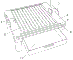
FIG. 1 is a perspective view of a finishing material cutting device for finishing according to the present utility model;
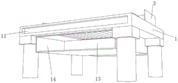
FIG. 2 is a block diagram of a scrap collecting bin of a finishing material cutting device for finishing according to the present utility model;
FIG. 3 is a view showing a structure of a supporting frame of a finishing material cutting device for finishing according to the present utility model;
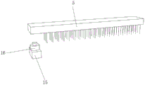
FIG. 4 is a view showing a brush structure of a finishing material cutting device for finishing according to the present utility model;
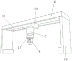
fig. 5 is a view showing a structure of a cutter of a finishing material cutting device for finishing according to the present utility model.
Legend description:
1. a work table; 2. a rubber cushion; 3. a fixing plate; 4. a first electric telescopic rod; 5. a brush; 6. a support plate; 7. a second electric telescopic rod; 8. a cutting knife; 9. a first electric slide rail; 10. a first slider; 11. the second electric sliding rail; 12. a support column; 13. a debris collection bin; 14. a support frame; 15. a second slider; 16. a first motor; 17. a second motor; 18. the third electric sliding rail; 19. and a third slider.
Detailed Description
The following description of the embodiments of the present utility model will be made clearly and completely with reference to the accompanying drawings, in which it is apparent that the embodiments described are only some embodiments of the present utility model, but not all embodiments. All other embodiments, which can be made by those skilled in the art based on the embodiments of the utility model without making any inventive effort, are intended to be within the scope of the utility model.
In the description of the present utility model, it should be noted that, directions or positional relationships indicated by terms such as "center", "upper", "lower", "left", "right", "vertical", "horizontal", "inner", "outer", etc., are based on directions or positional relationships shown in the drawings, are merely for convenience of description and simplification of description, and do not indicate or imply that the apparatus or element to be referred to must have a specific direction, be constructed and operated in the specific direction, and thus should not be construed as limiting the present utility model; the terms "first," "second," "third," and the like, are used for descriptive purposes only and are not to be construed as indicating or implying relative importance, and furthermore, unless explicitly specified and limited otherwise, the terms "mounted," "connected," "coupled," and the like are to be construed broadly, and may be fixedly coupled, detachably coupled, or integrally coupled, for example; can be mechanically or electrically connected; can be directly connected or indirectly connected through an intermediate medium, and can be communication between two elements. The specific meaning of the above terms in the present utility model will be understood in specific cases by those of ordinary skill in the art.
Referring to fig. 1-5, one embodiment provided by the present utility model is: the utility model provides a finishing material cutting device for fitment, which comprises a workbench 1, both ends intermediate position all fixedly connected with fixed plate 3 around the top of workstation 1, the corresponding one side central position of two fixed plates 3 all fixedly connected with first electric telescopic handle 4, place the finishing material that needs the cutting on support column 12, drive rubber cushion 2 through first electric telescopic handle 4 and fix the finishing material, prevent in the cutting process, the finishing material appears crookedly and cause the incision unevenness, thereby increase the fitment cost, workstation 1 both sides all run through and are provided with second electric slide rail 11, workstation 1 both sides all run through and sliding connection have first sliding block 10, two first sliding block 10 tops all fixedly connected with backup pad 6, backup pad 6 bottom runs through and is provided with third electric slide rail 18, the bottom of the supporting plate 6 is penetrated and connected with a third sliding block 19 in a sliding way, the bottom of the third sliding block 19 is fixedly connected with a second electric telescopic rod 7, under the working of the second electric telescopic rod 7, the distance between the cutting knife 8 and a finishing material can be adjusted according to actual demands, the bottom of the second electric telescopic rod 7 is fixedly connected with a second motor 17, through the arrangement of the second motor 17, the conversion between the transverse cutting and the longitudinal cutting of the cutting knife 8 can be realized, the left side and the right side of the top of the workbench 1 are penetrated and provided with a first electric sliding rail 9, the left side and the right side of the top of the workbench 1 are penetrated and connected with a second sliding block 15 in a sliding way, the tops of the two second sliding blocks 15 are fixedly connected with a first motor 16, when the cutting knife 8 works, the first motor 16 works to drive the brush 5 to rotate to the upper part of the first electric sliding rail 9, the bottom of the workbench 1 is fixedly connected with a supporting frame 14, the bottom of the inner wall of the supporting frame 14 is connected with a scrap collecting box 13 in a sliding way.
The rubber cushion 2 is fixedly connected to the other side of the two first electric telescopic rods 4, the rubber cushion 2 has the effects of avoiding damage to finishing materials, increasing friction force, enhancing stability of the finishing materials, enabling the two first sliding blocks 10 to slide in the second electric sliding rail 11, enabling the third sliding block 19 to slide in the third electric sliding rail 18, enabling the output end of the second motor 17 to be fixedly connected with the cutting knife 8, enabling the cutting knife 8 to move back and forth and left and right through the arrangement of the second electric sliding rail 11, the first sliding block 10, the supporting plate 6, the third electric sliding rail 18 and the third sliding block 19, enabling the two second sliding blocks 15 to slide in the first electric sliding rail 9, enabling the brush 5 to clean chips remained on the supporting columns 12, enabling the output ends of the two first electric sliding blocks 16 to be fixedly connected with the brush 5, enabling the middle positions between the left side and the right side of the inner wall of the workbench 1 to be fixedly connected with twelve supporting columns 12 which are evenly distributed, enabling chips generated in the cutting process to fall into the collecting box 13 through gaps between the supporting columns 12.
Working principle: firstly, place the fitment material that needs the cutting on support column 12, drive rubber cushion 2 through first electric telescopic handle 4 and fix the fitment material, prevent to appear crookedly and cause the incision unevenness at cutting in-process, thereby increase fitment cost, rubber cushion 2's effect lies in, avoid fitment material to receive the damage, simultaneously also can increase frictional force, strengthen fitment material's steadiness, through setting up second electric slide rail 11, first sliding block 10, backup pad 6, third electric slide rail 18 and third sliding block 19, can drive cutting knife 8 and carry out the back-and-forth motion, under the work of second electric telescopic handle 7, make cutting knife 8 can be according to actual demand adjustment and the distance between the fitment material, through setting up second motor 17, can realize cutting knife 8 horizontal and the conversion of vertical cutting, the piece that produces in cutting process, drop to in the collecting box 13 through the space between the support column 12, second piece 15 slides in first electric slide rail 9, thereby drive brush 5 cleans the piece that remains on the support column 12, when cutting knife 8 work, first brush 16 work drives electric slide rail 5 to be above 9.
Finally, it should be noted that: the foregoing description is only illustrative of the preferred embodiments of the present utility model, and although the present utility model has been described in detail with reference to the foregoing embodiments, it will be apparent to those skilled in the art that modifications may be made to the embodiments described, or equivalents may be substituted for elements thereof, and any modifications, equivalents, improvements or changes may be made without departing from the spirit and principles of the present utility model.
Claims (8)
1. Fitment material cutting device that fitment was used, including workstation (1), its characterized in that: the utility model discloses a workbench, including workstation (1), fixed plate (3) are all fixedly connected with in both ends intermediate position around workstation (1), two fixed plate (3) corresponding one side central point put equal fixedly connected with first electric telescopic handle (4), workstation (1) left and right sides all runs through and is provided with second electric slide rail (11), workstation (1) left and right sides all runs through and sliding connection has first sliding block (10), two equal fixedly connected with backup pad (6) in top of first sliding block (10), backup pad (6) bottom runs through and is provided with third electric slide rail (18), backup pad (6) bottom runs through and sliding connection has third sliding block (19), third sliding block (19) bottom fixedly connected with second electric telescopic handle (7), second electric telescopic handle (7) bottom fixedly connected with second motor (17), workstation (1) top left and right sides all runs through and is provided with first electric slide rail (9), workstation (1) top left and right sides all runs through and sliding connection has second sliding block (15) bottom (16) fixedly connected with frame (16), the bottom of the inner wall of the supporting frame (14) is connected with a scrap collecting box (13) in a sliding manner.
2. A finishing material cutting device for finishing as defined in claim 1, wherein: the other sides of the two first electric telescopic rods (4) are fixedly connected with rubber cushions (2).
3. A finishing material cutting device for finishing as defined in claim 1, wherein: both the first sliding blocks (10) slide in the second electric sliding rail (11).
4. A finishing material cutting device for finishing as defined in claim 1, wherein: the third sliding block (19) slides in the third electric sliding rail (18).
5. A finishing material cutting device for finishing as defined in claim 1, wherein: the output end of the second motor (17) is fixedly connected with a cutting knife (8).
6. A finishing material cutting device for finishing as defined in claim 1, wherein: both the second sliding blocks (15) slide in the first electric sliding rail (9).
7. A finishing material cutting device for finishing as defined in claim 1, wherein: the output ends of the two first motors (16) are fixedly connected with brushes (5).
8. A finishing material cutting device for finishing as defined in claim 1, wherein: twelve support columns (12) which are uniformly distributed are fixedly connected in the middle position between the left side and the right side of the inner wall of the workbench (1).
Priority Applications (1)
| Application Number | Priority Date | Filing Date | Title |
|---|---|---|---|
| CN202223399091.XU CN219190528U (en) | 2022-12-19 | 2022-12-19 | Fitment material cutting device that fitment was used |
Applications Claiming Priority (1)
| Application Number | Priority Date | Filing Date | Title |
|---|---|---|---|
| CN202223399091.XU CN219190528U (en) | 2022-12-19 | 2022-12-19 | Fitment material cutting device that fitment was used |
Publications (1)
| Publication Number | Publication Date |
|---|---|
| CN219190528U true CN219190528U (en) | 2023-06-16 |
Family
ID=86713250
Family Applications (1)
| Application Number | Title | Priority Date | Filing Date |
|---|---|---|---|
| CN202223399091.XU Active CN219190528U (en) | 2022-12-19 | 2022-12-19 | Fitment material cutting device that fitment was used |
Country Status (1)
| Country | Link |
|---|---|
| CN (1) | CN219190528U (en) |
-
2022
- 2022-12-19 CN CN202223399091.XU patent/CN219190528U/en active Active
Similar Documents
| Publication | Publication Date | Title |
|---|---|---|
| CN211466726U (en) | Cutting device is used in processing of wood furniture | |
| CN208645707U (en) | A kind of construction material cutter device | |
| CN106738072A (en) | A kind of cutter sweep of fiberboard | |
| CN213052898U (en) | Vertical milling machine with cleaning device | |
| CN210758235U (en) | Efficient cutting equipment for chair processing | |
| CN219190528U (en) | Fitment material cutting device that fitment was used | |
| CN214293559U (en) | Accurate location multiaspect saw of wood working digs machine | |
| CN216441774U (en) | Quick cutting device is used in aluminum product production | |
| CN211806649U (en) | A wooden decoration material cutting device for interior decoration | |
| CN213918453U (en) | Cutting device is used in production of building sound insulation building panel | |
| CN210909391U (en) | Wooden model grinding device | |
| CN213647634U (en) | Glass pad pasting is with tailorring device | |
| CN114290415A (en) | Cutting device for sponge | |
| CN214684533U (en) | A aluminum plate cutting equipment for producing of full aluminium house | |
| CN215328962U (en) | Multifunctional carpet processing device | |
| CN112705790A (en) | Milling device for processing metal saw blade | |
| CN208744913U (en) | A kind of portable multi-function PVC coloured silk shell blanking work platform | |
| CN215559873U (en) | Jig for cutting inner circle of optical glass | |
| CN213034826U (en) | Wood cutting device is used in furniture production | |
| CN211053900U (en) | High-efficient rocker arm saw | |
| CN211640032U (en) | A side cut device for furniture filler | |
| CN212948256U (en) | Cutting device is used in timber production | |
| CN220548411U (en) | Plank cutting machine is used in sofa production | |
| CN220903504U (en) | Fitment material cutting device that fitment was used | |
| CN220129031U (en) | Building materials processing deburring device |
Legal Events
| Date | Code | Title | Description |
|---|---|---|---|
| GR01 | Patent grant | ||
| GR01 | Patent grant |