CN219190428U - Automatic waste removing device for corrugated paper die cutting machine - Google Patents
Automatic waste removing device for corrugated paper die cutting machine Download PDFInfo
- Publication number
- CN219190428U CN219190428U CN202320063412.4U CN202320063412U CN219190428U CN 219190428 U CN219190428 U CN 219190428U CN 202320063412 U CN202320063412 U CN 202320063412U CN 219190428 U CN219190428 U CN 219190428U
- Authority
- CN
- China
- Prior art keywords
- cutting machine
- corrugated paper
- workbench
- threaded rod
- wall
- Prior art date
- Legal status (The legal status is an assumption and is not a legal conclusion. Google has not performed a legal analysis and makes no representation as to the accuracy of the status listed.)
- Active
Links
Images


Classifications
-
- Y—GENERAL TAGGING OF NEW TECHNOLOGICAL DEVELOPMENTS; GENERAL TAGGING OF CROSS-SECTIONAL TECHNOLOGIES SPANNING OVER SEVERAL SECTIONS OF THE IPC; TECHNICAL SUBJECTS COVERED BY FORMER USPC CROSS-REFERENCE ART COLLECTIONS [XRACs] AND DIGESTS
- Y02—TECHNOLOGIES OR APPLICATIONS FOR MITIGATION OR ADAPTATION AGAINST CLIMATE CHANGE
- Y02P—CLIMATE CHANGE MITIGATION TECHNOLOGIES IN THE PRODUCTION OR PROCESSING OF GOODS
- Y02P70/00—Climate change mitigation technologies in the production process for final industrial or consumer products
- Y02P70/10—Greenhouse gas [GHG] capture, material saving, heat recovery or other energy efficient measures, e.g. motor control, characterised by manufacturing processes, e.g. for rolling metal or metal working
Abstract
The utility model discloses an automatic waste clearing device for a corrugated paper die-cutting machine, which comprises a workbench, wherein the inner side of the workbench is of a cavity structure, an opening is formed in the outer wall of the bottom of the workbench, an adaptive dust collecting drawer is arranged in the opening, a guide hopper is fixedly connected to the inner wall of the top of the workbench, a storage plate is arranged at the top end of the workbench, a plurality of discharging holes are formed in an array on the upper end face of the storage plate, and an automatic waste clearing device is arranged on the outer side of the top of the workbench and used for clearing waste scraps generated during die-cutting above the storage plate. According to the utility model, the driving motor is started to enable the threaded rod to rotate, so that the threaded rod drives the threaded sleeve to transversely move through the limiting effect of the limiting slide rod, the cleaning roller is enabled to perform cleaning operation on scraps accumulated on the upper end face of the object plate, the cleaning roller guides the scraps to the inner side of the workbench through the discharging hole and finally vertically drops downwards into the dust collecting drawer to be collected, and the cleaning efficiency of the device is higher and the scraps can be automatically collected.
Description
Technical Field
The utility model relates to the technical field of die cutting machines, in particular to an automatic waste cleaning device for a corrugated paper die cutting machine.
Background
The die-cutting machine is mainly used for die-cutting (full-cut, half-cut), indentation, gold stamping operation, lamination and automatic waste discharge of corresponding non-metal materials, self-adhesive, EVA, double-sided adhesive, electronic rubber pads, mobile phone rubber pads and the like, and the die-cutting machine applies certain pressure through an embossing plate by utilizing a steel knife, a hardware die and a steel wire (or a template engraved by a steel plate), so that a printed product or a paperboard is rolled and cut into a certain shape, and is an important device for post-printing packaging, processing and forming.
The bulletin number is: the utility model discloses an automatic waste removing device for a corrugated paper die-cutting machine, and relates to the technical field of die-cutting machines. The utility model relates to an automatic waste removing device for a corrugated paper die cutting machine, which is characterized in that cut corrugated paper is conveyed through a conveying belt through a cleaning assembly, a motor is started at the moment, so that the motor drives a cleaning roller to rotate, and a hairbrush connected with the surface of the motor is driven to rotate together, so that the hairbrush is contacted with the surface of the corrugated paper, and waste scraps adsorbed on the surface of the corrugated paper are cleaned.
This patent has the following drawbacks: the scraps produced by the die cutting machine during die cutting often need to be manually processed, so that the working efficiency of the die cutting machine is reduced.
Therefore, the application now provides an automatic waste removing device for a corrugated paper die cutting machine to solve the problems.
Disclosure of Invention
The utility model aims to provide an automatic waste clearing device for a corrugated paper die-cutting machine, which aims to solve the problem that scraps generated during die-cutting of the die-cutting machine often need to be manually treated, so that the working efficiency of the die-cutting machine is reduced.
In order to achieve the above purpose, the present utility model provides the following technical solutions:
the utility model provides an automatic clear useless device of corrugated paper cross cutting machine, includes the workstation, the workstation inboard is the cavity structure, the opening has been seted up on the workstation bottom outer wall, be provided with the dust collection steamer tray of adaptation in the opening, fixedly connected with guide hopper on the workstation top inner wall, the workstation top is provided with puts the thing board, it is provided with a plurality of discharge openings to put thing board up end array, the workstation top outside is provided with automatic clear useless device for clean sweeps that produce when putting thing board top cross cutting.
Further, automatic clear useless device includes fixed frame, driving motor, threaded rod, thread bush, spacing slide bar and cleaning roller, fixed frame lateral wall and workstation lateral wall fixed connection, the rectangle mouth is seted up to fixed frame one side, fixed frame inboard transversely is provided with the threaded rod, the threaded rod both ends all rotate with fixed frame inner wall and are connected, just fixed frame lateral wall is passed to threaded rod one of them end is connected with driving motor, threaded rod is threaded on the lateral wall of threaded rod has the thread bush, transversely run through on the thread bush has spacing slide bar, fixedly connected with cleaning roller on the thread bush lateral wall, the cleaning roller passes the rectangle mouth and extends to directly over the thing board.
Further, the cleaning surface of the cleaning roller is in contact with the upper end surface of the object placing plate.
Further, the guide hopper is of a funnel-shaped structure.
Further, a hemispherical body is fixedly connected to the inner bottom wall of the dust collecting drawer, so that waste scraps are prevented from accumulating at one place.
Further, the four corners of the upper end face of the workbench are provided with mounting holes, and the four corners of the lower end face of the object placing plate are fixedly connected with inserted bars which are adapted to the mounting holes.
Compared with the prior art, the utility model has the beneficial effects that:
according to the utility model, the driving motor is started to enable the threaded rod to rotate, so that the threaded rod drives the threaded sleeve to transversely move through the limiting effect of the limiting slide rod, the cleaning roller is enabled to perform cleaning operation on the scraps accumulated on the upper end face of the object plate, the cleaning roller guides the scraps to the inner side of the workbench through the discharging hole, then the scraps fall into the guide hopper, are guided out through the discharging hole along the inner wall of the guide hopper, finally fall down vertically to the dust collection drawer for collection, and the cleaning efficiency of the device is higher, the scraps can be automatically collected, and the practicability is high.
Drawings
FIG. 1 is a schematic perspective view of an automatic waste cleaning device for a corrugated paper die-cutting machine;
FIG. 2 is a schematic elevational cross-sectional view of an automatic waste disposal device for a corrugated paper die-cutting machine;
FIG. 3 is a schematic diagram of the front view of an automatic waste cleaning device for a corrugated paper die-cutting machine;
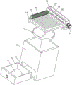
fig. 4 is a schematic diagram of an explosion state structure of an automatic waste cleaning device for a corrugated paper die-cutting machine.
In the figure: 10. a work table; 11. an opening; 12. a dust collecting drawer; 13. a guide hopper; 14. a storage plate; 15. a discharge hole; 16. a hemisphere; 20. a fixed frame; 21. a driving motor; 22. a threaded rod; 23. a thread sleeve; 24. a limit slide bar; 25. a cleaning roller; 26. rectangular mouth.
Detailed Description
The following description of the embodiments of the present utility model will be made clearly and completely with reference to the accompanying drawings, in which it is apparent that the embodiments described are only some embodiments of the present utility model, but not all embodiments. All other embodiments, which can be made by those skilled in the art based on the embodiments of the utility model without making any inventive effort, are intended to be within the scope of the utility model.
Referring to fig. 1-4, the present utility model provides the following technical solutions:
in this scheme, the workstation 10 inboard is cavity structure, has seted up opening 11 on the outer wall of workstation 10 bottom, is provided with the dust collection steamer tray 12 of adaptation in the opening 11, and welded fastening has guide hopper 13 on the inner wall of workstation 10 top, and the workstation 10 top is provided with puts thing board 14, should put thing board 14 and be used for placing the stupefied paper mould of playing after the cutting, puts thing board 14 up end array and is provided with a plurality of discharge openings 15, and the workstation 10 top outside is provided with automatic clear useless device for clean the sweeps that produce when putting thing board 14 top cross cutting.
The automatic waste removing device comprises a fixed frame 20, a driving motor 21, a threaded rod 22, a threaded sleeve 23, a limiting slide rod 24 and a cleaning roller 25, wherein the outer side wall of the fixed frame 20 is welded and fixed with the outer side wall of the workbench 10, a rectangular opening 26 is formed in one side of the fixed frame 20, a threaded rod 22 is transversely arranged on the inner side of the fixed frame 20, two ends of the threaded rod 22 are rotationally connected with the inner wall of the fixed frame 20, one end of the threaded rod 22 penetrates through the side wall of the fixed frame 20 to be connected with the driving motor 21, the driving motor 21 is the driving force of the threaded rod 22 and is used for driving the threaded rod 22 to rotate, the threaded sleeve 23 is connected with the outer side wall of the threaded rod 22 in a threaded manner, the limiting slide rod 24 transversely penetrates through the threaded sleeve 23, the cleaning roller 25 is welded and fixed on the side wall of the threaded sleeve 23, and the cleaning roller 25 penetrates through the rectangular opening 26 and extends to the position right above the storage plate 14.
The cleaning surface of the cleaning roller 25 contacts with the upper end surface of the storage plate 14, so that the cleaning roller 25 achieves the effect of cleaning the storage plate 14.
Wherein the hopper 13 is of a funnel-shaped structure for receiving the scraps falling down through the respective discharge holes 15.
Wherein, the hemispherical body 16 is welded and fixed on the inner bottom wall of the dust collecting drawer 12, so that the scraps are dispersed around the dust collecting drawer 12 when falling, thereby avoiding the scraps from accumulating at one place.
Wherein, the four corners of up end of workstation 10 have seted up the mounting hole, and four corners welded fastening of down end of putting thing board 14 have the inserted bar that is adapted to the mounting hole, in order to make be convenient for clear up in the workstation 10, should put thing board 14 and workstation 10 for detachable fixed through inserted bar and mounting hole, just can make to put thing board 14 and workstation 10 separation through the manual work.
Working principle: when the device is used, firstly, the driving motor 21 is started to enable the threaded rod 22 to rotate, so that the threaded rod 22 drives the threaded sleeve 23 to transversely move through the limiting action of the limiting sliding rod 24, so that the cleaning roller 25 can clean waste scraps accumulated on the upper end face of the counter plate 14, the cleaning roller 25 guides the waste scraps into the inner side of the workbench 10 through the discharging hole 15, then the waste scraps fall into the guide hopper 13, the waste scraps are guided out through the discharging hole along the inner wall of the guide hopper 13, finally fall into the dust collection drawer 12 vertically downwards to be collected, the dust collection drawer 12 is cleaned regularly, and the cleaning efficiency of the device is higher and the waste scraps can be automatically collected.
The present utility model has been illustrated by the above-described embodiments, but it should be understood that the above-described embodiments are for purposes of illustration and description only and are not intended to limit the utility model to the embodiments described.
Claims (6)
1. The utility model provides a corrugated paper cross cutting machine is with automatic clear useless device, includes workstation (10), its characterized in that: the utility model discloses a dust collection device for the automatic dust collection of the kitchen, including workstation (10), work platform (10), automatically, including work platform (10), dust collection drawer (13), sweeps, automatically, opening (11) have been seted up on the outer wall of workstation (10) bottom, be provided with dust collection drawer (12) of adaptation in opening (11), fixedly connected with guide hopper (13) on the inner wall of workstation (10) top, work platform (10) top is provided with puts thing board (14), it is provided with a plurality of discharge openings (15) to put thing board (14) up end array, the top outside of work platform (10) is provided with automatic clear useless device for sweep sweeps that produce when putting thing board (14) top cross cutting.
2. The automatic waste removing device for corrugated paper die cutting machine according to claim 1, wherein: automatic clear useless device includes fixed frame (20), driving motor (21), threaded rod (22), thread bush (23), spacing slide bar (24) and cleaning roller (25), fixed frame (20) lateral wall and workstation (10) lateral wall fixed connection, rectangle mouth (26) are seted up to fixed frame (20) one side, fixed frame (20) inboard transversely is provided with threaded rod (22), threaded rod (22) both ends all rotate with fixed frame (20) inner wall and are connected, just threaded rod (22) wherein one end is passed fixed frame (20) lateral wall and is connected with driving motor (21), threaded connection has thread bush (23) on threaded rod (22) lateral wall, transversely run through on thread bush (23) spacing slide bar (24), fixedly connected with cleaning roller (25) on thread bush (23) lateral wall, cleaning roller (25) pass rectangle mouth (26) and extend to put thing board (14) directly over.
3. The automatic waste removing device for corrugated paper die cutting machine according to claim 2, wherein: the cleaning surface of the cleaning roller (25) is contacted with the upper end surface of the object placing plate (14).
4. The automatic waste removing device for corrugated paper die cutting machine according to claim 2, wherein: the guide hopper (13) is of a funnel-shaped structure.
5. The automatic waste removing device for corrugated paper die cutting machine according to claim 1, wherein: the inner bottom wall of the dust collecting drawer (12) is fixedly connected with a hemispherical body (16) so as to prevent waste scraps from accumulating at one place.
6. The automatic waste removing device for corrugated paper die cutting machine according to claim 1, wherein: four corners of the upper end face of the workbench (10) are provided with mounting holes, and four corners of the lower end face of the object placing plate (14) are fixedly connected with inserted bars which are adapted to the mounting holes.
Priority Applications (1)
| Application Number | Priority Date | Filing Date | Title |
|---|---|---|---|
| CN202320063412.4U CN219190428U (en) | 2023-01-10 | 2023-01-10 | Automatic waste removing device for corrugated paper die cutting machine |
Applications Claiming Priority (1)
| Application Number | Priority Date | Filing Date | Title |
|---|---|---|---|
| CN202320063412.4U CN219190428U (en) | 2023-01-10 | 2023-01-10 | Automatic waste removing device for corrugated paper die cutting machine |
Publications (1)
| Publication Number | Publication Date |
|---|---|
| CN219190428U true CN219190428U (en) | 2023-06-16 |
Family
ID=86703011
Family Applications (1)
| Application Number | Title | Priority Date | Filing Date |
|---|---|---|---|
| CN202320063412.4U Active CN219190428U (en) | 2023-01-10 | 2023-01-10 | Automatic waste removing device for corrugated paper die cutting machine |
Country Status (1)
| Country | Link |
|---|---|
| CN (1) | CN219190428U (en) |
-
2023
- 2023-01-10 CN CN202320063412.4U patent/CN219190428U/en active Active
Similar Documents
| Publication | Publication Date | Title |
|---|---|---|
| CN112792860A (en) | EPE automatic punching machine | |
| CN217166773U (en) | Plate cutting device | |
| CN219190428U (en) | Automatic waste removing device for corrugated paper die cutting machine | |
| CN210881058U (en) | High-speed punch device capable of automatically collecting waste materials | |
| CN208084482U (en) | A kind of automatic waste material cleaning plant of die-cutting machine | |
| CN214418913U (en) | Paper cutting mechanism and pop can cover lower cover device | |
| CN214726811U (en) | Automatic clear useless device of cross cutting machine | |
| CN214352983U (en) | Clear useless device of cross cutting machine | |
| CN214352853U (en) | Waste collecting device for die cutting machine | |
| CN210126123U (en) | Waste clearing mechanism of corrugated board die-cutting machine | |
| CN210148810U (en) | Dust removal device of corrugated board grooving machine | |
| CN220593459U (en) | High-speed water-based printing die-cutting forming machine with material receiving mechanism | |
| CN220593395U (en) | Waste recycling device for corrugated board die cutting machine | |
| CN117445475B (en) | Packing carton slitter edge punching device | |
| CN220593460U (en) | Punching equipment for absorbent paper | |
| CN216609242U (en) | Foam stamping die | |
| CN220428608U (en) | Chip removal device for graphene diaphragm die-cutting machine | |
| CN219563344U (en) | Clear useless device of cross cutting machine | |
| CN212707125U (en) | Automatic cutting and packaging equipment for corrugated board production | |
| CN219404513U (en) | Waste discharge mechanism of die cutting machine | |
| CN115837773B (en) | Automatic production device and production method for food packaging boxes | |
| CN216881817U (en) | Cylinder belt punching jig | |
| CN214238609U (en) | Paper cross cutting machine with dustproof function of collecting | |
| CN219381772U (en) | Carton printing slotting die-cutting machine device | |
| CN215319151U (en) | Die-cutting machine easy to clean |
Legal Events
| Date | Code | Title | Description |
|---|---|---|---|
| GR01 | Patent grant | ||
| GR01 | Patent grant |