CN219190395U - OCA section equipment for optical cement processing - Google Patents
OCA section equipment for optical cement processing Download PDFInfo
- Publication number
- CN219190395U CN219190395U CN202223364122.8U CN202223364122U CN219190395U CN 219190395 U CN219190395 U CN 219190395U CN 202223364122 U CN202223364122 U CN 202223364122U CN 219190395 U CN219190395 U CN 219190395U
- Authority
- CN
- China
- Prior art keywords
- fixedly connected
- oca
- optical cement
- processing
- block
- Prior art date
- Legal status (The legal status is an assumption and is not a legal conclusion. Google has not performed a legal analysis and makes no representation as to the accuracy of the status listed.)
- Active
Links
Images


Landscapes
- Grinding And Polishing Of Tertiary Curved Surfaces And Surfaces With Complex Shapes (AREA)
Abstract
The utility model relates to OCA slicing equipment for optical cement processing, which comprises a storage bin, wherein the upper end part of the storage bin is fixedly connected with a processing table, the upper end part of the processing table is provided with a fixing component, the upper end part of the processing table is fixedly connected with a supporting frame, the supporting frame is provided with a slicing component, and the fixing component comprises a mounting seat, and one end of the mounting seat is fixedly connected with the upper end part of the processing table. This an OCA slicing device for optical cement processing, through the cooperation of fixing screw and extrusion piece, when placing the work piece on to the mount pad, can promote and loosen the extrusion piece and extrude preliminary fixedly to the work piece, and drive the both sides grip block through rotating the fixing screw and be close to the back, fix again the work piece extrusion to improve the stability when the work piece is fixed, and because the extrusion piece can reciprocate, and the grip block can transversely adjust, thereby can adjust fixed specification according to the work piece specification, reach the effect of being convenient for stabilize fixed different specification work pieces.
Description
Technical Field
The utility model relates to the technical field of optical cement processing, in particular to OCA slicing equipment for optical cement processing.
Background
OCA optical adhesive is one of the important touch screen raw materials, and is characterized in that optical acrylic adhesive is made into a base material-free adhesive tape, then a release film is respectively attached to the upper and lower bottom layers, and the base material-free adhesive tape is a double-sided adhesive tape which is the optimal adhesive for the touch screen.
After solidification is accomplished in production to optical cement, need use slicing equipment to slice optical cement generally, an OCA slicing equipment for optical film processing such as the publication number CN211761923U discloses, including frame and base, the lower extreme of frame is provided with the base, frame and base pass through bolt fixed connection, the inside of frame is provided with the locker, locker and frame pass through bolt fixed connection, the upper end of frame is provided with the workstation, the front end surface side of workstation is provided with the control panel, control panel and power electric connection, the upper end of workstation is provided with places the platform, changes the mode of carrying out the work piece with traditional adoption anchor clamps into current through fixed establishment and carries out the fixed to the work piece, adopts the telescopic cylinder to drive under the telescopic link motion and makes the work piece can firm fixed the table end of placing the platform, has avoided the unstable phenomenon of work piece fixation.
However, the fixing mechanism in the above application is inconvenient to adjust and fix the specifications according to the specifications of the workpieces, so that the workpieces with different specifications are inconvenient to fix stably, and the applicability of the whole equipment is reduced, so that an OCA slicing device for optical cement processing is provided to solve the above problems.
Disclosure of Invention
Aiming at the defects of the prior art, the utility model provides OCA slicing equipment for optical cement processing, which has the advantages of being convenient for stably fixing workpieces with different specifications and the like, and solves the problem that the workpieces with different specifications are inconvenient to stably fix.
In order to achieve the above purpose, the present utility model provides the following technical solutions: the OCA slicing equipment for optical cement processing comprises a storage bin, wherein the upper end part of the storage bin is fixedly connected with a processing table, the upper end part of the processing table is provided with a fixing assembly, the upper end part of the processing table is fixedly connected with a supporting frame, and the supporting frame is provided with a slicing assembly;
the fixed subassembly includes the mount pad of one end and the upper end fixed connection of processing platform, the upper end fixedly connected with riser of mount pad, the rear side the back sliding connection of riser has one end to run through the connecting rod of rear side riser, fixedly connected with spring between the inboard of connecting rod and the back of rear side riser, the upper end fixedly connected with supporting seat of processing platform, the inside screw thread connection of supporting seat has fixing screw, the one end that fixing screw is close to the mount pad rotates and is connected with the connecting plate, the inboard fixedly connected with grip block of connecting plate, the cutting groove has all been seted up to the upper end of connecting plate, grip block and mount pad.
Further, the number of the cutting grooves is a plurality of, and the plurality of the cutting grooves are distributed in a front-back equidistant mode.
Further, the number of the vertical plates is two, the two vertical plates are symmetrically distributed in front and back, and one end, far away from the vertical plates, of the connecting rod is T-shaped.
Further, the supporting seat is L-shaped, a threaded hole is formed in the supporting seat, and the threaded hole is matched with threads on the outer side of the fixing screw.
Further, the section subassembly includes the inboard sliding connection's of one end and support frame connecting block, the upper end fixedly connected with rack of connecting block, the upper end fixedly connected with biax motor of support frame, biax motor's output shaft fixedly connected with bull stick, the outside fixedly connected with one end and rack-meshed gear of bull stick, the right side the outside fixedly connected with servo motor of connecting block, servo motor's output shaft fixedly connected with one end runs through right side connecting block and rotates the adjusting screw who is connected with left side connecting block, adjusting screw's outside threaded connection has the installation piece, the lower tip fixed mounting of installation piece has the hydraulic stem, the output fixedly connected with motor storehouse of hydraulic stem, the front of motor storehouse is provided with the blade, the cross bar of installation piece is run through to the inboard fixedly connected with of connecting block.
Further, a second threaded hole is formed in the mounting block, and the second threaded hole is matched with threads on the outer side of the adjusting screw.
Further, the connecting block is L-shaped, the upper end fixedly connected with one end of the connecting block extends to the inside sliding block of the support frame, the inside of the support frame is provided with a sliding groove positioned on the outer side of the sliding block, and the sliding groove is in sliding connection with the sliding block.
Further, a driving motor is arranged on the inner side of the motor bin, and the blade is fixedly connected to an output shaft of the driving motor.
Compared with the prior art, the technical scheme of the application has the following beneficial effects:
1. this an OCA slicing device for optical cement processing, through the cooperation of fixing screw and extrusion piece, when placing the work piece on to the mount pad, can promote and loosen the extrusion piece and extrude preliminary fixedly to the work piece, and drive the both sides grip block through rotating the fixing screw and be close to the back, fix again the work piece extrusion to improve the stability when the work piece is fixed, and because the extrusion piece can reciprocate, and the grip block can transversely adjust, thereby can adjust fixed specification according to the work piece specification, reach the effect of being convenient for stabilize fixed different specification work pieces.
2. This an OCA slicing device for optical cement processing, through the cooperation of biax motor, servo motor and hydraulic stem, make the biax motor accessible gear of start drive blade back-and-forth movement with the rack, and the servo motor of start can drive blade lateral shifting, and the pneumatic cylinder of start can drive blade longitudinal movement, makes the blade can be adjusted in many positions, improves cutting efficiency.
Drawings
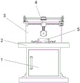
FIG. 1 is a schematic diagram of the overall structure of the present utility model;
FIG. 2 is a schematic view of a slicing assembly according to the present utility model;
FIG. 3 is a schematic view of a fixing assembly according to the present utility model.
In the figure: 1 storage bin, 2 processing bench, 3 support frame, 4 section subassemblies, 41 connecting block, 42 rack, 43 hydraulic stem, 44 bull stick, 45 biax motors, 46 adjusting screw, 47 horizontal pole, 48 gear, 49 servo motor, 410 installation piece, 411 blade, 412 motor bin, 5 fixed subassembly, 51 mount pad, 52 riser, 53 connecting rod, 54 spring, 55 extrusion piece, 56 supporting seat, 57 fixing screw, 58 connecting plate, 59 grip block, 510 cutting groove.
Description of the embodiments
The following description of the embodiments of the present utility model will be made clearly and completely with reference to the accompanying drawings, in which it is apparent that the embodiments described are only some embodiments of the present utility model, but not all embodiments. All other embodiments, which can be made by those skilled in the art based on the embodiments of the utility model without making any inventive effort, are intended to be within the scope of the utility model.
In order to enable the whole device to stably fix workpieces of different specifications to improve the applicability of the device, please refer to fig. 1 and 3, an OCA slicing device for optical cement processing in this embodiment includes a storage bin 1, a processing table 2 is fixedly connected to an upper end portion of the storage bin 1, a fixing component 5 is disposed at an upper end portion of the processing table 2, a supporting frame 3 is fixedly connected to an upper end portion of the processing table 2, and a slicing component 4 is disposed on the supporting frame 3.
The fixed component 5 comprises a mounting seat 51, one end of which is fixedly connected with the upper end part of the processing table 2, a vertical plate 52 is fixedly connected with the upper end part of the mounting seat 51, a connecting rod 53, one end of which penetrates through the rear vertical plate 52, is slidably connected with the back surface of the rear vertical plate 52, and a spring 54 is fixedly connected between the inner side of the connecting rod 53 and the back surface of the rear vertical plate 52.
The number of the vertical plates 52 is two, the two vertical plates 52 are symmetrically distributed in front and back, one end of the connecting rod 53, which is far away from the vertical plates 52, is T-shaped, and the spring 54 is fixedly connected between the T-shaped end of the connecting rod 53 and the rear vertical plate 52, so that the reset spring 54 can push the extrusion block 55 to extrude a workpiece.
The upper end fixedly connected with supporting seat 56 of processing platform 2, the inside threaded connection of supporting seat 56 has fixing screw 57, and the supporting seat 56 is the L font, and the screw hole has been seted up to the inside of supporting seat 56, and the screw thread of screw hole and fixing screw 57 outside cooperates each other, makes pivoted screw 57 can transversely move on supporting seat 56, and fixing screw 57 is close to the one end rotation of mount pad 51 and is connected with connecting plate 58.
The inboard fixedly connected with grip block 59 of connecting plate 58, the lower tip fixedly connected with one end of connecting plate 58 extends to the inside stopper of processing platform 2, and the upper end of processing platform 2 has seted up the spacing groove that is located the stopper outside, and it can stabilize lateral shifting to restrict connecting plate 58.
The connecting plate 58, the clamping blocks 59 and the upper end parts of the mounting seats 51 are provided with a plurality of cutting grooves 510, the plurality of cutting grooves 510 are distributed at equal intervals in front and back, and the blades 411 can penetrate through the cutting grooves 510 to transversely cut the workpiece which is clamped and fixed into slices.
In this embodiment, when the workpiece is placed on the mounting seat 51, the pressing block 55 can be pushed and pressed to press the workpiece to be primarily fixed, and the fixing screw 57 is rotated to drive the clamping blocks 59 at two sides to be close to the workpiece to press the workpiece to be secondarily fixed, so that the stability of workpiece fixing is improved, and the pressing block 55 can be moved up and down, and the clamping blocks 59 can be transversely adjusted, so that the fixing specification can be adjusted according to the workpiece specification.
Embodiment two: on the basis of the first embodiment, in order to adjust the blade 411 in multiple directions and improve the cutting efficiency, please refer to fig. 2, in this embodiment, the slicing assembly 4 includes a connecting block 41 with one end slidably connected with the inner side of the support frame 3, the connecting block 41 is L-shaped, the upper end of the connecting block 41 is fixedly connected with a slider with one end extending to the inner side of the support frame 3, the inner side of the support frame 3 is provided with a sliding groove located on the outer side of the slider, the sliding groove is slidably connected with the sliding block, and the sliding block and the sliding groove are T-shaped, so that the connecting block 41 can slide back and forth in the stable state of the support frame 3.
The upper end fixedly connected with rack 42 of connecting block 41, the upper end fixed mounting of support frame 3 has biax motor 45, and the output shaft fixedly connected with bull stick 44 of biax motor 45, the outside fixedly connected with one end of bull stick 44 with rack 42 engaged gear 48, the outside fixed mounting of right side connecting block 41 has servo motor 49.
An output shaft of the servo motor 49 is fixedly connected with an adjusting screw 46, one end of the adjusting screw 46 penetrates through the right connecting block 41 and is rotationally connected with the left connecting block 41, an installation block 410 is connected to the outer side of the adjusting screw 46 in a threaded mode, a second threaded hole is formed in the installation block 410, the second threaded hole is matched with threads on the outer side of the adjusting screw 46, and the rotating adjusting screw 46 can drive the installation block 410 to transversely reciprocate.
The lower tip fixed mounting of installation piece 410 has hydraulic stem 43, and the output fixedly connected with motor storehouse 412 of hydraulic stem 43, and the front of motor storehouse 412 is provided with blade 411, and the inboard of motor storehouse 412 is provided with driving motor, and blade 411 fixed connection is on driving motor's output shaft, and the inboard fixedly connected with of connecting block 41 runs through the horizontal pole 47 of installation piece 410.
In this embodiment, the started dual-shaft motor 45 can drive the blade 411 to move back and forth through the gear 48 and the rack 42, the started servo motor 49 can drive the blade 411 to move transversely, and the started pneumatic cylinder 43 can drive the blade 411 to move longitudinally, so that the blade 411 can be adjusted in multiple directions, and the cutting efficiency is improved.
The working principle of the embodiment is as follows:
after the extrusion block 55 is pushed to slide to one side close to the rear vertical plate 52, a workpiece can be placed on the mounting seat 51, the extrusion block 55 can be loosened, so that the reset spring 54 pushes the extrusion block 55 to extrude the workpiece to be primarily extruded and fixed, the left side and the right side of the workpiece can be clamped and fixed after the fixing screw 57 on the left side and the right side is rotated to drive the clamping blocks 59 on the two sides to be close to each other, so that the stability of workpiece fixing is improved, and the extrusion block 55 can move back and forth in the mounting seat 51, the clamping blocks 59 can be transversely adjusted through the fixing screw 57, and the fixing specification can be adjusted according to the workpiece specification, so that the effect of conveniently and stably fixing workpieces with different specifications is achieved.
The double-shaft motor 45 that starts can drive the connecting block 41 back and forth through gear 48 and rack 42 cooperation, can drive the blade 411 and follow back and forth movement, and the servo motor 49 that starts can drive the blade 411 and follow lateral shifting after adjusting screw 46 drives installation piece 410 left and right movement, and the pneumatic cylinder 43 that starts can drive blade 411 longitudinal movement, makes blade 411 back and forth, about and control diversified regulation, makes blade 411 pass a plurality of cutting groove 510 in proper order, cuts the work piece into the strip fast, improves cutting efficiency.
It is noted that relational terms such as first and second, and the like are used solely to distinguish one entity or action from another entity or action without necessarily requiring or implying any actual such relationship or order between such entities or actions. Moreover, the terms "comprises," "comprising," or any other variation thereof, are intended to cover a non-exclusive inclusion, such that a process, method, article, or apparatus that comprises a list of elements does not include only those elements but may include other elements not expressly listed or inherent to such process, method, article, or apparatus. Without further limitation, an element defined by the phrase "comprising one … …" does not exclude the presence of other like elements in a process, method, article, or apparatus that comprises the element.
Although embodiments of the present utility model have been shown and described, it will be understood by those skilled in the art that various changes, modifications, substitutions and alterations can be made therein without departing from the principles and spirit of the utility model, the scope of which is defined in the appended claims and their equivalents.
Claims (8)
1. An OCA slicing device for optical cement processing, comprising a storage bin (1), characterized in that: the upper end part of the storage bin (1) is fixedly connected with a processing table (2), the upper end part of the processing table (2) is provided with a fixing assembly (5), the upper end part of the processing table (2) is fixedly connected with a supporting frame (3), and the supporting frame (3) is provided with a slicing assembly (4);
the utility model provides a fixed subassembly (5) is including one end and processing bench (2) upper end fixed connection's mount pad (51), the upper end fixedly connected with riser (52) of mount pad (51), the rear side the back sliding connection of riser (52) has connecting rod (53) that one end runs through rear side riser (52), fixedly connected with spring (54) between the inboard of connecting rod (53) and the back of rear side riser (52), the upper end fixedly connected with supporting seat (56) of processing bench (2), the inside threaded connection of supporting seat (56) has dead screw (57), the one end rotation that dead screw (57) is close to mount pad (51) is connected with connecting plate (58), the inboard fixedly connected with grip block (59) of connecting plate (58), cutting groove (510) have all been seted up to the upper end of grip block (59) and mount pad (51).
2. The OCA slicing apparatus for optical cement processing of claim 1, wherein: the number of the cutting grooves (510) is a plurality, and the cutting grooves (510) are distributed in a front-back equidistant mode.
3. The OCA slicing apparatus for optical cement processing of claim 1, wherein: the number of the vertical plates (52) is two, the two vertical plates (52) are symmetrically distributed in front and back, and one end, far away from the vertical plates (52), of each connecting rod (53) is T-shaped.
4. The OCA slicing apparatus for optical cement processing of claim 1, wherein: the supporting seat (56) is L-shaped, a threaded hole is formed in the supporting seat (56), and the threaded hole is matched with threads on the outer side of the fixing screw (57).
5. The OCA slicing apparatus for optical cement processing of claim 1, wherein: the utility model provides a section subassembly (4) including one end and inboard sliding connection's of support frame (3 connecting block (41), the upper end fixedly connected with rack (42) of connecting block (41), the upper end fixed mounting of support frame (3) has biax motor (45), the output shaft fixedly connected with bull stick (44) of biax motor (45), the outside fixedly connected with one end of bull stick (44) and rack (42) meshed gear (48), the right side the outside fixedly connected with servo motor (49) of connecting block (41), the output shaft fixedly connected with one end of servo motor (49) runs through right side connecting block (41) and rotates adjusting screw (46) of being connected with left side connecting block (41), the outside threaded connection of adjusting screw (46) has installation piece (410), the lower tip fixed mounting of installation piece (410) has hydraulic stem (43), the output fixedly connected with motor storehouse (412) of hydraulic stem (43), the front of motor storehouse (412) is provided with blade (411), the inboard fixedly connected with of connecting block (41) runs through installation piece (47).
6. The OCA slicing apparatus for optical cement processing of claim 5, wherein: a second threaded hole is formed in the mounting block (410), and the second threaded hole is matched with threads on the outer side of the adjusting screw (46).
7. The OCA slicing apparatus for optical cement processing of claim 5, wherein: the connecting block (41) is L-shaped, the upper end part of the connecting block (41) is fixedly connected with a sliding block, one end of the sliding block extends to the inside of the supporting frame (3), a sliding groove positioned at the outer side of the sliding block is formed in the inner side of the supporting frame (3), and the sliding groove is in sliding connection with the sliding block.
8. The OCA slicing apparatus for optical cement processing of claim 5, wherein: the inside of motor storehouse (412) is provided with driving motor, blade (411) fixed connection is on driving motor's output shaft.
Priority Applications (1)
| Application Number | Priority Date | Filing Date | Title |
|---|---|---|---|
| CN202223364122.8U CN219190395U (en) | 2022-12-15 | 2022-12-15 | OCA section equipment for optical cement processing |
Applications Claiming Priority (1)
| Application Number | Priority Date | Filing Date | Title |
|---|---|---|---|
| CN202223364122.8U CN219190395U (en) | 2022-12-15 | 2022-12-15 | OCA section equipment for optical cement processing |
Publications (1)
| Publication Number | Publication Date |
|---|---|
| CN219190395U true CN219190395U (en) | 2023-06-16 |
Family
ID=86719689
Family Applications (1)
| Application Number | Title | Priority Date | Filing Date |
|---|---|---|---|
| CN202223364122.8U Active CN219190395U (en) | 2022-12-15 | 2022-12-15 | OCA section equipment for optical cement processing |
Country Status (1)
| Country | Link |
|---|---|
| CN (1) | CN219190395U (en) |
-
2022
- 2022-12-15 CN CN202223364122.8U patent/CN219190395U/en active Active
Similar Documents
| Publication | Publication Date | Title |
|---|---|---|
| CN209969714U (en) | Feeding device of cutting machine | |
| CN219190395U (en) | OCA section equipment for optical cement processing | |
| CN213702023U (en) | Profile sawing mechanism | |
| CN219484379U (en) | Feeding mechanism of plate shearing machine | |
| CN215588018U (en) | Double-end precision cutting saw equipment for aluminum alloy section | |
| CN216151301U (en) | Application device of plate shearing machine blanking die and auxiliary support | |
| CN209466368U (en) | A kind of decorative pattern timber processing machine tool | |
| CN221391450U (en) | Wood square cutting device | |
| CN219788437U (en) | Board cutting device for indoor decoration | |
| CN113102817A (en) | Plate shearing equipment for new energy automobile part production and use method | |
| CN220445215U (en) | Integrated numerical control double-end precision cutting saw of aluminium alloy | |
| CN221834385U (en) | Cutting device for notebook production | |
| CN220741267U (en) | Food production cutting mechanism | |
| CN215702246U (en) | Multifunctional edge cutting processing device for injection molding part | |
| CN221475515U (en) | Cutting equipment | |
| CN221314532U (en) | Timber engraver with fixed function | |
| CN221890971U (en) | Adjustable aluminum profile cutting die | |
| CN220724670U (en) | Cloth cutting table capable of cleaning cloth fragments | |
| CN220178293U (en) | Cutting device is used in wardrobe processing production | |
| CN219685951U (en) | Auxiliary pushing device of plate cutting saw | |
| CN220882538U (en) | Slicing equipment for plate processing | |
| CN117944106B (en) | Panel processing cutting auxiliary assembly convenient to clamping | |
| CN220044754U (en) | Fresh meat slicer | |
| CN221872660U (en) | Monocrystalline bar cuts cutting equipment | |
| CN219724785U (en) | Aluminum product cutting machine fixing tool with supporting structure |
Legal Events
| Date | Code | Title | Description |
|---|---|---|---|
| GR01 | Patent grant | ||
| GR01 | Patent grant |