CN219189458U - Planer fixture - Google Patents
Planer fixture Download PDFInfo
- Publication number
- CN219189458U CN219189458U CN202223562948.5U CN202223562948U CN219189458U CN 219189458 U CN219189458 U CN 219189458U CN 202223562948 U CN202223562948 U CN 202223562948U CN 219189458 U CN219189458 U CN 219189458U
- Authority
- CN
- China
- Prior art keywords
- block
- base
- hole
- opening
- planer
- Prior art date
- Legal status (The legal status is an assumption and is not a legal conclusion. Google has not performed a legal analysis and makes no representation as to the accuracy of the status listed.)
- Active
Links
Images

Classifications
-
- Y—GENERAL TAGGING OF NEW TECHNOLOGICAL DEVELOPMENTS; GENERAL TAGGING OF CROSS-SECTIONAL TECHNOLOGIES SPANNING OVER SEVERAL SECTIONS OF THE IPC; TECHNICAL SUBJECTS COVERED BY FORMER USPC CROSS-REFERENCE ART COLLECTIONS [XRACs] AND DIGESTS
- Y02—TECHNOLOGIES OR APPLICATIONS FOR MITIGATION OR ADAPTATION AGAINST CLIMATE CHANGE
- Y02P—CLIMATE CHANGE MITIGATION TECHNOLOGIES IN THE PRODUCTION OR PROCESSING OF GOODS
- Y02P70/00—Climate change mitigation technologies in the production process for final industrial or consumer products
- Y02P70/10—Greenhouse gas [GHG] capture, material saving, heat recovery or other energy efficient measures, e.g. motor control, characterised by manufacturing processes, e.g. for rolling metal or metal working
Landscapes
- Milling, Drilling, And Turning Of Wood (AREA)
Abstract
The utility model relates to a planer fixture, which comprises a base, wherein the base is provided with a first opening, a first oil cylinder is arranged in the first opening, the output end of the first oil cylinder is connected with a connecting seat, two sides of the connecting seat are respectively provided with a second opening, each second opening is connected with one end of a rod body, one end of a rotating block is rotatably arranged at the other end of the rod body, and the other end of the rotating block is connected with a pressing plate; the top of the base is also connected with a cover plate, a plurality of jacking blocks are arranged on the cover plate and the base close to the pressing plate, each jacking block is connected with one end of a wedge block butt joint plate through a wedge block, and the other end of the wedge block butt joint plate is connected with the output end of the second oil cylinder. According to the utility model, the wedge block is arranged, and the inclined plane is also arranged on the top block, so that the wedge block moves and drives the top block to do lifting motion, and the wedge block can be matched with an uneven surface of a workpiece, so that the phenomenon of deflection and vibration of the workpiece after clamping is avoided, the processing quality of the workpiece is improved, and the rejection rate is reduced.
Description
Technical Field
The utility model relates to the technical field of mechanical equipment, in particular to a planer fixture.
Background
The fixture is one fixture for clamping workpiece and guiding cutter and is specially designed for certain work procedure. At present, the traditional clamp can play a good clamping and positioning effect on a workpiece with a flat surface, but if the workpiece with an uneven surface is clamped, the surface of the workpiece is inclined, so that a vibrating knife is easy to appear in the subsequent planing and milling process, the surface of the workpiece generates a chatter mark, the quality of the workpiece is further affected, and the rejection rate is improved.
Disclosure of Invention
In view of the above-mentioned shortcomings of the prior art, it is an object of the present utility model to provide a planer fixture that solves one or more of the problems of the prior art.
In order to achieve the above purpose, the technical scheme of the utility model is as follows:
the planer fixture comprises a base, wherein the base is provided with a first opening, a first oil cylinder is arranged in the first opening, the output end of the first oil cylinder is connected with a connecting seat, two sides of the connecting seat are respectively provided with a second opening, each second opening is connected with one end of a rod body, one end of a rotating block is rotatably arranged at the other end of the rod body, and the other end of the rotating block is connected with a pressing plate; the top of base still connects the apron, is being close to clamp plate department, on apron and base set up a plurality of kicking blocks jointly, every the kicking block is all connected with the one end of voussoir butt joint board through the voussoir, the other end of voussoir butt joint board is connected with the output of second hydro-cylinder, the side that the second hydro-cylinder was fixed in the base.
Further, a first hole is formed in the other end of the rod body, one end of the rotating block extends into the first hole, a spiral groove is formed in the outer side of the rotating block, a pair of protruding columns are further arranged in the outer side of the rod body, and each protruding column is provided with a part extending into the hole and connected with the spiral groove.
Further, the other end of the rotating block is provided with a protruding part, and the outer side of the protruding part is provided with external threads.
Further, a second hole is formed in the pressing plate and is used for being matched with the protruding portion, and an inner thread which can be matched with the outer thread is formed in the hole wall of the second hole.
Further, the pressing plate has a part of area overlapping with a part of area of the top block.
Further, the top block is made of rubber.
Further, the contact surface of the top block and the pressing plate is a plane or a curved surface.
Compared with the prior art, the utility model has the following beneficial technical effects that
The utility model has simple structure and convenient use, and the wedge block is arranged, and the inclined plane is arranged on the top block, so that the wedge block moves and drives the top block to do lifting motion, and the wedge block can be matched with the uneven surface of the workpiece, thereby avoiding the phenomenon of deflection and vibration of the workpiece after clamping, improving the processing quality of the workpiece and reducing the rejection rate.
And (II) further, the convex columns are arranged on the rod body and are in butt joint with the spiral grooves on the rotating block, so that the linear motion pair of the rod body is changed into a revolute pair of the rotating block, and meanwhile, the pressing plate is in threaded connection with the rotating block, so that the pressing plate can downwards move and press the workpiece while rotating, and the clamping stability is ensured.
Drawings
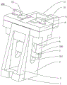
Fig. 1 shows a schematic structural view i of a planer fixture according to an embodiment of the utility model.
Fig. 2 shows a schematic structural view ii of a planer fixture according to an embodiment of the utility model.
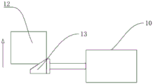
Fig. 3 shows a schematic view of the planer fixture of an embodiment of the utility model with the top block not extended.
Fig. 4 shows a schematic view of the extension of the top block of the planer fixture according to an embodiment of the utility model.
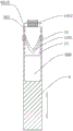
Fig. 5 shows a schematic partial structure of a planer jig according to an embodiment of the utility model.
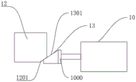
The reference numerals in the drawings: 1. a support block; 2. reinforcing ribs; 3. a base; 300. a first opening; 301. a through hole; 4. a first cylinder; 5. a connecting seat; 500. a second opening; 6. a rod body; 600. a first hole; 601. a guide plate; 6010. a guide hole; 7. a guide seat; 8. a cover plate; 9. a pressing plate; 900. a second hole; 10. a second cylinder; 1000. wedge block butt joint plates; 11. the second oil cylinder mounting seat; 12. a top block; 1201. a first inclined surface; 13. wedge blocks; 1301. a second inclined surface; 14. a rotating block; 1401. a spiral groove; 1402. a protruding portion; 15. and (5) a convex column.
Detailed Description
In order to make the objects, technical solutions and advantages of the present utility model more apparent, the planer fixture according to the present utility model will be described in further detail with reference to the accompanying drawings and the detailed description. The advantages and features of the present utility model will become more apparent from the following description. It should be noted that the drawings are in a very simplified form and are all to a non-precise scale, merely for the purpose of facilitating and clearly aiding in the description of embodiments of the utility model. For a better understanding of the utility model with objects, features and advantages, refer to the drawings. It should be understood that the structures, proportions, sizes, etc. shown in the drawings are for illustration purposes only and should not be construed as limiting the utility model to the extent that any modifications, changes in the proportions, or adjustments of the sizes of structures, proportions, or otherwise, used in the practice of the utility model, are included in the spirit and scope of the utility model which is otherwise, without departing from the spirit or essential characteristics thereof.
Referring to fig. 1, the planer fixture of the present embodiment includes a base 3, and the outer sides of the base 3 are respectively connected with a supporting block 1 and a reinforcing rib 2, so as to improve the structural strength of the base 3. The two sides of the base 3 are provided with first openings 300, the first oil cylinder 4 is fixed in the first openings 300, the output end of the first oil cylinder 4 is connected with the connecting seat 5, and the two sides of the connecting seat 5 are respectively provided with second openings 500. Referring to fig. 1, through holes 301 are further formed on the left and right sides of the base 3, the left and right sides of the connection seat 5 respectively extend from the through holes 301 and are connected to one end of the rod body 6 through the second opening 500, and a guide seat 7 is further disposed in the base 3 outside the rod body 6.
Referring to fig. 1 and 5, the other end of the rod body 6 extends into the base, one end of the rotating block 14 is rotatably disposed at the other end of the rod body 6, and the other end of the rotating block 14 is connected with the pressing plate 9. Specifically, a first hole 600 is formed at the other end of the rod body 6, one end of the rotating block 14 extends into the first hole 600, a spiral groove 1401 is formed at the outer side of the rotating block 14, a pair of protruding columns 15 are further arranged at the outer side of the rod body 6, and each protruding column 15 has a part extending into the first hole 600 and is connected with the spiral groove 1401. The other end of the rotating block 14 has a protruding portion 1402, and an external thread is provided on the outer side of the protruding portion 1402. With continued reference to fig. 1 and 5, in order to ensure the reliability of the lifting and lowering of the rotating block 14, a guide plate 601 is fixedly connected to the end of the rod body 6, and a guide hole 6010 for the moving of the rotating block 14 is formed in the guide plate 601.
Further, referring to fig. 1 to 5, a cover plate 8 is further connected to the top of the base 3, a plurality of top blocks 12 are disposed in the cover plate 8 and the base 3 near the pressing plate 9, cavities for moving the top blocks 12 are formed on the cover plate 8 and the base 3, each top block 12 is connected to one end of a wedge block butt plate 1000 through a wedge block 13, the other end of the wedge block butt plate 1000 is connected to an output end of a second cylinder 10, and the second cylinder 10 is fixed to a side surface of the base 3 through a second cylinder mounting seat 11.
Further, referring to fig. 3 and 4, the top block 12 has a first inclined surface 1201, and the wedge 13 has a second inclined surface 1301.
Further, referring to fig. 1, a second hole 900 is formed in the pressing plate 9, the second hole 900 is used for matching with the protruding portion 1402, an inner thread capable of matching with the outer thread is formed on a hole wall of the second hole 900, in order to ensure that the workpiece can be pressed, the pressing plate 9 has a part of area overlapping with a part of area of the top block 12, specifically, a part of area of the pressing plate 9 occupies 1/3-2/3 of the total area, and similarly, a part of area of the top block 12 occupies 1/3-2/3 of the total area.
Further, referring to fig. 1 and 2, in order to ensure that the surface of the workpiece is not scratched when the workpiece is contacted, the top block 12 is made of a rubber material. Meanwhile, the contact surface of the top block 12 and the pressing plate 9 can be a plane or a curved surface, when the material of the workpiece is hard alloy, the contact surface of the top block 12 and the pressing plate 9 can be a plane, and when the material of the workpiece is aluminum alloy, the contact surface of the top block 12 and the pressing plate 9 can be a curved surface so as to adapt to clamping of workpieces of different materials.
The specific working process of the utility model is as follows:
referring to fig. 1 to 5, in use, the present utility model is placed at the left and right ends of the planer workbench, then two ends of a workpiece (the workpiece in this embodiment adopts a guide rail) are respectively placed on the surfaces of the top blocks 12 of the planer jigs, the wedge 13 is started by the second cylinder 10 and driven to move forward by the output end thereof, and the wedge 13 has the second inclined plane 1301 and contacts the first inclined plane 1201 of the top block 12, so that the top block 12 is driven to rise in the moving process of the wedge 13, the uneven surface of the workpiece is matched in the rising process of the top block 12, and the second cylinder 10 is self-locked after the matching is completed.
Further, referring to fig. 1 and 5, at this time, the output end of the first oil cylinder 4 moves downward to drive the connecting seat 5 and the rod bodies 6 at two ends of the connecting seat 5 to move downward, and since the rod bodies 6 are connected with the spiral grooves 1401 of the rotating blocks 14 through the protruding columns 15, the protruding columns 15 move along the spiral grooves 1401 in the downward moving process of the rod bodies 6, so that the linear motion pair of the rod bodies 6 is converted into the revolute pair of the rotating blocks 14, and since the protruding portions 1402 of the rotating blocks 14 are in threaded connection with the pressing plates 9, the rotating blocks 14 rotate and simultaneously drive the pressing plates 9 to rotate and press downwards at a certain angle, and the pressing plates 9 rotate until a part of the pressing plates coincides with a part of the jacking blocks 12 and compress the workpieces, thereby ensuring the stability and reliability of workpiece clamping. The technical features of the above-described embodiments may be arbitrarily combined, and all possible combinations of the technical features in the above-described embodiments are not described for brevity of description, however, as long as there is no contradiction between the combinations of the technical features, they should be considered as the scope of the description.
The above examples illustrate only a few embodiments of the utility model, which are described in detail and are not to be construed as limiting the scope of the utility model. It should be noted that it will be apparent to those skilled in the art that several variations and modifications can be made without departing from the spirit of the utility model, which are all within the scope of the utility model. Accordingly, the scope of protection of the present utility model is to be determined by the appended claims.
Claims (7)
1. Planer anchor clamps, its characterized in that: the device comprises a base, wherein the base is provided with a first opening, a first oil cylinder is arranged in the first opening, the output end of the first oil cylinder is connected with a connecting seat, two sides of the connecting seat are respectively provided with a second opening, each second opening is connected with one end of a rod body, one end of a rotating block is rotatably arranged at the other end of the rod body, and the other end of the rotating block is connected with a pressing plate; the top of base still connects the apron, is being close to clamp plate department, on apron and base set up a plurality of kicking blocks jointly, every the kicking block is all connected with the one end of voussoir butt joint board through the voussoir, the other end of voussoir butt joint board is connected with the output of second hydro-cylinder, the side that the second hydro-cylinder was fixed in the base.
2. Planer fixture according to claim 1, characterized in that: the other end of the rod body is provided with a first hole, one end of the rotating block extends into the first hole, the outer side of the rotating block is provided with a spiral groove, the outer side of the rod body is further provided with a pair of convex columns, and each convex column is provided with a part extending into the hole and connected with the spiral groove.
3. Planer fixture according to claim 2, characterized in that: the other end of the rotating block is provided with a protruding part, and the outer side of the protruding part is provided with external threads.
4. A planer fixture as claimed in claim 3, wherein: the pressing plate is provided with a second hole, the second hole is used for being matched with the protruding portion, and the hole wall of the second hole is provided with an internal thread which can be matched with the external thread.
5. Planer fixture according to claim 1, characterized in that: the pressing plate has a portion of an area overlapping a portion of an area of the top block.
6. Planer fixture as claimed in claim 5, characterized in that: the top block is made of rubber.
7. Planer fixture as claimed in claim 6, characterized in that: the contact surface of the top block and the pressing plate is a plane or a curved surface.
Priority Applications (1)
| Application Number | Priority Date | Filing Date | Title |
|---|---|---|---|
| CN202223562948.5U CN219189458U (en) | 2022-12-30 | 2022-12-30 | Planer fixture |
Applications Claiming Priority (1)
| Application Number | Priority Date | Filing Date | Title |
|---|---|---|---|
| CN202223562948.5U CN219189458U (en) | 2022-12-30 | 2022-12-30 | Planer fixture |
Publications (1)
| Publication Number | Publication Date |
|---|---|
| CN219189458U true CN219189458U (en) | 2023-06-16 |
Family
ID=86702080
Family Applications (1)
| Application Number | Title | Priority Date | Filing Date |
|---|---|---|---|
| CN202223562948.5U Active CN219189458U (en) | 2022-12-30 | 2022-12-30 | Planer fixture |
Country Status (1)
| Country | Link |
|---|---|
| CN (1) | CN219189458U (en) |
-
2022
- 2022-12-30 CN CN202223562948.5U patent/CN219189458U/en active Active
Similar Documents
| Publication | Publication Date | Title |
|---|---|---|
| CN209773664U (en) | Novel medium-speed wire numerical control linear cutting machine | |
| CN211414374U (en) | CNC electrode machining clamp | |
| CN210024543U (en) | Tool clamp for machine tool | |
| CN219189458U (en) | Planer fixture | |
| CN212071192U (en) | Clamp for machining motorcycle accessories | |
| CN211414375U (en) | CNC axle type part boring grab | |
| CN209793215U (en) | Electric automatization anchor clamps of removable chuck | |
| CN111168425A (en) | Clamp for machining inclined plane of small end of connecting rod | |
| CN211639138U (en) | Clamp for drilling center hole of square workpiece | |
| CN212217885U (en) | Fixing device for machining based on universal machine tool | |
| CN215545044U (en) | Auxiliary tool for drilling machine | |
| CN215091633U (en) | Welding fixture with good fixing effect | |
| CN212526143U (en) | Cell-phone production is with numerical control drilling processingequipment | |
| CN209754604U (en) | Clamping device for machine tool machining | |
| CN211565181U (en) | Combined clamp | |
| CN210790094U (en) | Horizontal processing tool of connecting piece | |
| CN210121770U (en) | Fixture of milling machine | |
| CN218503860U (en) | Work piece adaptation clamping worktable | |
| CN216657973U (en) | Mechanical arm clamping device | |
| CN218427066U (en) | Workpiece fixing device for planing table type milling and boring machine | |
| CN210413657U (en) | Automatic clamping device for machining | |
| CN210451203U (en) | Metal cutting machine convenient to adjust cutting position | |
| CN215510088U (en) | Machine tool clamping jig | |
| CN218946947U (en) | Milling cylinder plane clamp | |
| CN216262887U (en) | Stamping device for aluminum formwork edge sealing |
Legal Events
| Date | Code | Title | Description |
|---|---|---|---|
| GR01 | Patent grant | ||
| GR01 | Patent grant |