CN219166312U - Water knockout drum and water knockout subassembly and cleaning device - Google Patents
Water knockout drum and water knockout subassembly and cleaning device Download PDFInfo
- Publication number
- CN219166312U CN219166312U CN202222691042.7U CN202222691042U CN219166312U CN 219166312 U CN219166312 U CN 219166312U CN 202222691042 U CN202222691042 U CN 202222691042U CN 219166312 U CN219166312 U CN 219166312U
- Authority
- CN
- China
- Prior art keywords
- branch
- water
- liquid
- flow channel
- communicated
- Prior art date
- Legal status (The legal status is an assumption and is not a legal conclusion. Google has not performed a legal analysis and makes no representation as to the accuracy of the status listed.)
- Active
Links
- XLYOFNOQVPJJNP-UHFFFAOYSA-N water Substances O XLYOFNOQVPJJNP-UHFFFAOYSA-N 0.000 title claims abstract description 82
- 238000004140 cleaning Methods 0.000 title claims abstract description 31
- 239000007788 liquid Substances 0.000 claims description 76
- 238000005507 spraying Methods 0.000 claims description 18
- 230000003139 buffering effect Effects 0.000 claims description 5
- 239000007921 spray Substances 0.000 claims description 4
- 239000012780 transparent material Substances 0.000 claims description 3
- 238000010276 construction Methods 0.000 claims description 2
- 238000000926 separation method Methods 0.000 abstract description 3
- 238000005096 rolling process Methods 0.000 description 31
- 238000010586 diagram Methods 0.000 description 5
- 239000010985 leather Substances 0.000 description 5
- 230000005540 biological transmission Effects 0.000 description 4
- 230000007246 mechanism Effects 0.000 description 4
- 230000009286 beneficial effect Effects 0.000 description 2
- 230000000694 effects Effects 0.000 description 2
- 230000004048 modification Effects 0.000 description 1
- 238000012986 modification Methods 0.000 description 1
- 230000001737 promoting effect Effects 0.000 description 1
- 239000010865 sewage Substances 0.000 description 1
Images


Classifications
-
- Y—GENERAL TAGGING OF NEW TECHNOLOGICAL DEVELOPMENTS; GENERAL TAGGING OF CROSS-SECTIONAL TECHNOLOGIES SPANNING OVER SEVERAL SECTIONS OF THE IPC; TECHNICAL SUBJECTS COVERED BY FORMER USPC CROSS-REFERENCE ART COLLECTIONS [XRACs] AND DIGESTS
- Y02—TECHNOLOGIES OR APPLICATIONS FOR MITIGATION OR ADAPTATION AGAINST CLIMATE CHANGE
- Y02B—CLIMATE CHANGE MITIGATION TECHNOLOGIES RELATED TO BUILDINGS, e.g. HOUSING, HOUSE APPLIANCES OR RELATED END-USER APPLICATIONS
- Y02B40/00—Technologies aiming at improving the efficiency of home appliances, e.g. induction cooking or efficient technologies for refrigerators, freezers or dish washers
Landscapes
- Cleaning In General (AREA)
Abstract
The utility model discloses a water separator, a water separation assembly and cleaning equipment, which belong to the technical field of cleaning equipment.
Description
Technical Field
The utility model relates to the technical field of cleaning equipment, in particular to a water separator, a water separation assembly and cleaning equipment.
Background
The current cleaning equipment is designed with a plurality of rolling brushes and corresponding cleaning mechanisms, the cleaning mechanisms generally adopt a multi-way valve, a leather hose and the like to convey cleaning liquid, the hose is easy to deform and is easy to separate from a liquid spraying piece under the action of external force, the stability is poor, the liquid is conveyed through the leather hose, and the phenomenon of uneven water outlet exists.
Disclosure of Invention
The utility model aims to provide a water separator, a water separation assembly and cleaning equipment, wherein the water separator is used for conveying cleaning liquid instead of a multi-way valve, a leather hose and the like, the stability is good, and the water separator is provided with a buffer cavity which can buffer water flow, so that the water flow is more stable, and the water outlet is more uniform.
To achieve the purpose, the utility model adopts the following technical scheme:
a water separator comprises a water inlet, a plurality of water outlets, a runner and a buffer cavity for buffering water flow, wherein the runner is provided with an inlet and a plurality of outlets communicated with the inlet, the water inlet is communicated with the inlet of the runner through the buffer cavity, and each water outlet is correspondingly communicated with the outlet of one runner.
In some embodiments, the flow channel comprises a main flow channel and a plurality of branch flow channels communicated with the main flow channel, wherein an inlet of the main flow channel is communicated with the water inlet through the buffer cavity, and an outlet of each branch flow channel is correspondingly communicated with a water outlet.
In some embodiments, the flow channel comprises a main flow channel with an outlet and two branch flow channels, wherein the inlets of the two branch flow channels are communicated with the outlet of the main flow channel, the central axes of the two branch flow channels are on the same straight line, and the extending directions of the two branch flow channels are opposite.
In some embodiments, the length and width dimensions of each of the branching flow channels are the same.
In some embodiments, the top cover of the water separator is made of a transparent material.
The water diversion assembly comprises the water diversion device and a plurality of liquid spraying pieces, wherein each liquid spraying piece is provided with a liquid inlet and at least one liquid outlet, and each water outlet of the water diversion device is correspondingly communicated with the liquid inlet of one liquid spraying piece.
In some embodiments, the liquid spraying piece is provided with a liquid inlet channel communicated with the liquid inlet, and liquid outlet channels symmetrically arranged on two sides of the liquid inlet channel and communicated with the liquid inlet channel, each liquid outlet channel comprises a first branch, a second branch and a third branch which are arranged along a first direction in an extending mode, and a fourth branch and a fifth branch which are arranged along a second direction in an extending mode, the third branch is located between the first branch and the second branch, the first branch is communicated with the second branch through the fourth branch, two ends of the second branch are respectively communicated with a third branch through a fifth branch, and two ends of each third branch are respectively communicated with the liquid outlet.
In some embodiments, the liquid spraying piece is further provided with a buffer flow channel, and the liquid inlet channel is communicated with the liquid inlet through the buffer flow channel.
The cleaning equipment comprises the water diversion assembly, a plurality of rolling brushes, and at least one of the rolling brushes is of a built-in motor structure.
In some embodiments, the roller brush further comprises a housing provided with a suction opening located above the roller brush.
The utility model has the beneficial effects that: adopt the water knockout drum to replace the transportation of cleaning solution such as multipotency valve and leather hose, the steadiness is good to, the water knockout drum is equipped with the cushion chamber, can cushion rivers, makes the rivers more steady, and the water yield is more even.
Drawings
FIG. 1 is a block diagram of a water separator of the present utility model;
FIG. 2 is a view showing the construction of the internal flow path of the water separator according to the present utility model;
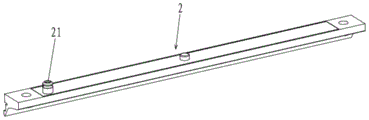
FIG. 3 is a block diagram of a spray member of the present utility model;
FIG. 4 is a schematic view of the internal flow passages of the spray member of the present utility model;
FIG. 5 is a simplified schematic diagram of the internal flow passages of the spray member of the present utility model;
FIG. 6 is a block diagram of a cleaning apparatus of the present utility model;
FIG. 7 is a bottom view of the housing of the cleaning apparatus of the present utility model;
FIG. 8 is a block diagram of a roller brush of a cleaning apparatus of the present utility model;
FIG. 9 is a view showing a structure of a position of a rolling brush and a surface to be cleaned according to the present utility model;
wherein: 1-a water separator; 11-a main runner; 12-branch flow passage; 13-a buffer chamber; 14-a water inlet; 15-a water outlet; 16-top cover; 2-spraying part; 21-a liquid inlet; 22-a liquid outlet; 23-liquid inlet flow channel; 24-a liquid outlet flow channel; 241-first leg; 242-a second leg; 243-third leg; 244-fourth branch, 245-fifth branch, 25-buffer flow channel, 31-end cover; 41-rolling brush; 42-driving a motor; 5-a suction port; 6-surface to be cleaned.
Detailed Description
The utility model is described in further detail below with reference to the accompanying drawings.
Referring to fig. 1 and 2, a water separator 1 includes a water inlet 14, a plurality of water outlets 15, a flow channel and a buffer chamber 13 for buffering water flow, the flow channel has an inlet and a plurality of outlets communicating with the inlet, the water inlet 14 is communicated with the inlet of the flow channel through the buffer chamber 13, and each water outlet 15 is correspondingly communicated with an outlet of a flow channel.
The cleaning solution flows in from the water inlet 14 under the power provided by the power mechanism such as the water pump, then is buffered in the buffer cavity 13, and flows to the runner after the buffer cavity is full of water, so the arrangement of the buffer cavity prevents the cleaning solution from directly rushing to the runner, so that the flow of the cleaning solution is smoother, the water outlet is more stable, and moreover, the water separator 1 is adopted to replace a multi-way valve, a leather hose and the like for conveying the cleaning solution, so that the stability is good.
The flow channel comprises a main flow channel 11 and a plurality of branch flow channels 12 communicated with the main flow channel 11, wherein an inlet of the main flow channel 11 is communicated with a water inlet 14 through a buffer cavity 13, and an outlet of each branch flow channel 12 is correspondingly communicated with a water outlet 15.
The flow channel comprises a main flow channel 11 with an outlet and two branch flow channels 12, wherein the inlets of the two branch flow channels 12 are communicated with the outlet of the main flow channel 11, the central axes of the two branch flow channels 12 are positioned on the same straight line, and the extending directions of the two branch flow channels 12 are opposite.
The length and width dimensions of each of the branch flow passages 12 are the same, thus promoting uniform flow of cleaning liquid to each of the water outlets 15.
The water separator 1 is provided with a top cover 16, the top cover 16 is made of transparent materials, so that the situation of water flow in a runner can be seen, and the situations of blockage, water shortage and the like can be found in time.
Referring to fig. 1 to 5, a water diversion assembly includes the water diversion device 1, and further includes a plurality of liquid spraying members 2, each liquid spraying member 2 is provided with a liquid inlet 21 and at least one liquid outlet 22, and each water outlet 15 of the water diversion device 1 is correspondingly communicated with the liquid inlet 21 of one liquid spraying member 2. The water knockout drum 1 evenly carries the cleaning solution to spraying member 2, then spraying member 2's liquid outlet 22 spouts the cleaning solution to round brush 41, and the water outlet is more stable, and the cleaning performance is better.
Referring to fig. 4 and 5, the liquid spraying member 2 is provided with a plurality of liquid outlets 22, and the plurality of liquid outlets 22 are uniformly arranged on the same straight line, for example, the number of the liquid outlets 22 is 8;
the liquid spraying member 2 is provided with a plurality of stages of flow passages, the liquid inlet 21 is communicated with a plurality of liquid outlets 22 through the plurality of stages of flow passages, and the plurality of stages of flow passages are in a roundabout shape, so that the roundabout multistage flow passages are beneficial to compact structure.
Specifically, the multi-stage flow channel comprises a liquid inlet flow channel 23 and liquid outlet flow channels 24 symmetrically arranged at two sides of the liquid inlet flow channel 23. The liquid inlet channels 23 are communicated with the liquid inlet 21, and each liquid outlet channel 24 is communicated with the liquid inlet channel 23. In this embodiment, the liquid inlet channels 23 have an outlet, and each liquid outlet channel 24 is connected to the outlet. Of course, in other embodiments, a plurality of outlets may be provided, each of which communicates with a liquid outlet 24.
Further, each of the liquid outlet channels 24 includes a first branch 241, a second branch 242, and a third branch 243 extending in the first direction X, and a fourth branch 244 and a fifth branch 245 extending in the second direction Y. The first branch 241, the second branch 242 and the third branch 243 are disposed at intervals along the second direction, and the third branch 243 is located between the first branch 241 and the second branch 242. The first branch 241 is communicated with the second branch 242 through the fourth branch 244, two ends of the second branch 242 are respectively communicated with a third branch 243 through the fifth branch 245, and two ends of each third branch 243 are respectively communicated with a liquid outlet 22. The flow direction of the liquid in the multi-stage flow channel is shown by the arrow in fig. 5. The first direction X is preferably perpendicular to the second direction Y.
Thus, the liquid outlets 22 are simultaneously communicated with 8 liquid outlets 22 through the multi-stage flow channels, and the liquid outlet flow channels 24 are symmetrically arranged, so that the water quantity of the liquid outlet flow channels 24 is basically the same, and the water outlet is uniform and stable.
Further, the multistage flow channel further comprises a buffer flow channel 25, and the liquid inlet channel 23 is communicated with the liquid inlet 21 through the buffer flow channel 25. By providing the buffer flow passage 25, the liquid is made to flow more stably, ensuring uniform final water discharge.
Referring to fig. 6 to 9, a cleaning apparatus includes the water diversion assembly, and further includes a plurality of rolling brushes 41, wherein at least one of the rolling brushes 41 has a built-in motor structure, for example, when the number of the rolling brushes 41 is two, both the rolling brushes 41 may have a built-in motor structure, or one of the rolling brushes may have a built-in motor structure, and the other rolling brush may have an external motor structure.
The cleaning device comprises a shell 3, a rolling brush 41 is rotatably connected to the shell 3, the rolling brush 41 comprises a cylinder, and cleaning pieces are arranged on the outer circumferential surface of the cylinder;
when the rolling brush 41 is of a built-in motor structure, a corresponding driving motor 42 is placed in the barrel, a rotating shaft of the driving motor 42 is connected with the shell 3 through a connecting piece, the rotating shaft of the driving motor 42 is driven to be fixed, a shell of the driving motor 42 rotates, and the rolling brush 41 is driven to rotate; or the driving motor 42 is fixed on the shell 3, the cylinder is sleeved on the driving motor 42, the rotating shaft of the driving motor 42 is in driving connection with the cylinder through a connecting piece, and the rotating shaft of the driving motor 42 drives the cylinder to move.
When the rolling brush 41 is of an external motor structure, the corresponding driving motor 42 can be fixed on the shell 3, and the rolling brush 41 is driven to rotate through a transmission mechanism such as a transmission gear, a transmission belt or a transmission piece.
The rolling brushes 41 are arranged side by side and can be simultaneously contacted with the surface 6 to be cleaned, for example, when the number of the rolling brushes 41 is two, the two rolling brushes 41 can be simultaneously contacted with the surface 6 to be cleaned, and the rotation directions of the two rolling brushes 41 can be the same or opposite, wherein when the rotation directions are opposite, the cleaning effect is better.
Further, the casing 3 is provided with a suction port 5, and the suction port 5 is connected with a suction source, so that negative pressure suction force can be generated, and dirt, sewage and the like can be sucked away;
the suction openings 5 may be provided above the roll brushes 41, and preferably the suction openings 5 may be provided between the roll brushes 41, and this may be engaged in a direction opposite to the rotation direction of the roll brushes 41, thereby further improving the suction effect.
Further, the rolling brush 41 is detachable and is convenient to assemble and maintain.
Whether the rolling brush 41 is of an internal motor structure or an external motor structure, the rolling brush 41 can be assembled through side drawing, namely, the rolling brush can be disassembled and assembled in a drawing or inserting mode from the side part of the shell 3, specifically, an opening is arranged on the side part of the shell 3, a detachable end cover 31 is arranged on the opening, the end part of the rolling brush 41 is rotatably connected with the end cover 31, and the end cover 31 can be detachably assembled in the shell 3 through structures such as a buckle, a button, a magnetic attraction and the like. The plurality of rolling brushes 41 and the plurality of end caps 31 may be in one-to-one correspondence, the plurality of end caps 31 may be all disposed on the same side of the housing 3, and the plurality of end caps 31 may be disposed in an integrated structure.
If the rolling brush 41 is an external motor structure, besides being capable of being assembled in a side-drawing manner, the rolling brush 41 can be assembled in the shell 3 in a lifting manner, namely, the rolling brush 41 is assembled in an upward lifting manner or a downward lifting manner, specifically, the shell 3 is provided with a clamping groove, the end part of the rolling brush 41 is rotatably connected with a clamping piece, and the clamping piece is matched and connected with the clamping groove to realize the assembly and the disassembly through the clamping structure.
What has been disclosed above is but a few embodiments of the present utility model. It will be apparent to those skilled in the art that various modifications and improvements can be made without departing from the spirit of the utility model.
Claims (10)
1. The utility model provides a water knockout drum (1), its characterized in that includes water inlet (14), a plurality of delivery port (15), runner and is used for buffering the buffering chamber (13) of rivers, the runner has entry and intercommunication a plurality of export of entry, water inlet (14) are through buffering chamber (13) with the entry of runner is linked together, every delivery port (15) corresponds the intercommunication one the export of runner.
2. A water separator (1) according to claim 1, wherein the flow channel comprises a main flow channel (11) and a plurality of branch flow channels (12) communicated with the main flow channel (11), the inlet of the main flow channel (11) is communicated with the water inlet (14) through the buffer cavity (13), and the outlet of each branch flow channel (12) is correspondingly communicated with a water outlet (15).
3. A water separator (1) according to claim 2, characterized in that the flow channel comprises a main flow channel (11) with an outlet and two branch flow channels (12), wherein the inlets of the two branch flow channels (12) are communicated with the outlet of the main flow channel (11), the central axes of the two branch flow channels (12) are on the same straight line, and the extending directions of the two branch flow channels (12) are opposite.
4. A water separator (1) according to claim 3, wherein the length and width dimensions of each of the branch flow channels (12) are the same.
5. A water separator (1) according to claim 1, characterized in that the water separator (1) has a top cover (16) made of transparent material.
6. A water diversion assembly, characterized by comprising the water diversion device (1) as claimed in any one of claims 1-5, and further comprising a plurality of liquid spraying pieces (2), wherein each liquid spraying piece (2) is provided with a liquid inlet (21) and at least one liquid outlet (22), and each water outlet (15) of the water diversion device (1) is correspondingly communicated with the liquid inlet (21) of one liquid spraying piece (2).
7. The water diversion assembly according to claim 6, wherein the liquid spraying piece (2) is provided with a liquid inlet channel (23) communicated with the liquid inlet (21) and liquid outlet channels (24) symmetrically arranged at two sides of the liquid inlet channel (23) and communicated with the liquid inlet channel (23), each liquid outlet channel (24) comprises a first branch (241), a second branch (242) and a third branch (243) which are arranged along a first direction in an extending manner, a fourth branch (244) and a fifth branch (245) which are arranged along a second direction in an extending manner, the third branch (243) is positioned between the first branch (241) and the second branch (242), the first branch (241) is communicated with the second branch (242) through the fourth branch (244), two ends of the second branch (242) are respectively communicated with a third branch (243) through a fifth branch (245), and two ends of each third branch (243) are respectively communicated with the liquid outlet (22).
8. A water distribution assembly according to claim 7, wherein the spray member (2) is further provided with a buffer flow channel (25), and the liquid inlet flow channel (23) is in communication with the liquid inlet (21) via the buffer flow channel (25).
9. A cleaning appliance comprising a water distribution assembly according to any one of claims 6 to 8, and further comprising a plurality of roller brushes (41), at least one of said roller brushes (41) being of a built-in motor construction.
10. A cleaning device according to claim 9, further comprising a housing (3), said housing (3) being provided with a suction opening (5), said suction opening (5) being located above said roller brush (41).
Priority Applications (1)
| Application Number | Priority Date | Filing Date | Title |
|---|---|---|---|
| CN202222691042.7U CN219166312U (en) | 2022-10-12 | 2022-10-12 | Water knockout drum and water knockout subassembly and cleaning device |
Applications Claiming Priority (1)
| Application Number | Priority Date | Filing Date | Title |
|---|---|---|---|
| CN202222691042.7U CN219166312U (en) | 2022-10-12 | 2022-10-12 | Water knockout drum and water knockout subassembly and cleaning device |
Publications (1)
| Publication Number | Publication Date |
|---|---|
| CN219166312U true CN219166312U (en) | 2023-06-13 |
Family
ID=86669789
Family Applications (1)
| Application Number | Title | Priority Date | Filing Date |
|---|---|---|---|
| CN202222691042.7U Active CN219166312U (en) | 2022-10-12 | 2022-10-12 | Water knockout drum and water knockout subassembly and cleaning device |
Country Status (1)
| Country | Link |
|---|---|
| CN (1) | CN219166312U (en) |
-
2022
- 2022-10-12 CN CN202222691042.7U patent/CN219166312U/en active Active
Similar Documents
| Publication | Publication Date | Title |
|---|---|---|
| EP2085009B1 (en) | Cleaning apparatus | |
| EP3857138A1 (en) | Fluid driven solar panel cleaning system | |
| US20230241527A1 (en) | Bubble machine with multiple bubble making ports | |
| CN219166312U (en) | Water knockout drum and water knockout subassembly and cleaning device | |
| CN114607808B (en) | Shower bath | |
| CN216776860U (en) | A scrubbing brush and cleaning machine for cleaning machine | |
| CN118000623A (en) | Water distribution components, water supply devices and cleaning equipment | |
| CN215521375U (en) | Volute structure and double-pump system of water pump, cleaning machine | |
| CN113546903B (en) | A driving assembly for a cleaning machine and the cleaning machine | |
| CN109915616A (en) | An ice cream machine discharge valve | |
| CN222058234U (en) | Liquid conveying device and cleaning equipment | |
| TWM672541U (en) | Docking station and cleaning system | |
| CN217419856U (en) | Water pump, flushing system and intelligent closestool | |
| CN118490003A (en) | Hair care comb | |
| CN214945227U (en) | Impeller structure, double-pump system and cleaning machine | |
| CN217524986U (en) | Surface cleaning apparatus | |
| CN214998133U (en) | Double-head pump for water dispenser | |
| CN215521376U (en) | Volute structure and double-pump system of water pump, cleaning machine | |
| CN216077721U (en) | Volute structure and double-pump system of water pump, cleaning machine | |
| CN211341045U (en) | Distributor integrated nozzle | |
| CN212816099U (en) | Dust collector floor brush and dust collector | |
| CN211247522U (en) | Hand-held high-pressure cleaning machine and cleaning machine | |
| CN223143027U (en) | Liquid guiding comb seat | |
| WO2023020182A1 (en) | Additive release module, control method and laundry treatment apparatus | |
| CN219594484U (en) | Floor washing machine |
Legal Events
| Date | Code | Title | Description |
|---|---|---|---|
| GR01 | Patent grant | ||
| GR01 | Patent grant |