CN219166301U - Washing machine - Google Patents

Washing machine Download PDF

Info

Publication number
CN219166301U
CN219166301U CN202223062000.3U CN202223062000U CN219166301U CN 219166301 U CN219166301 U CN 219166301U CN 202223062000 U CN202223062000 U CN 202223062000U CN 219166301 U CN219166301 U CN 219166301U
Authority
CN
China
Prior art keywords
water level
level detection
water
detection part
side wall
Prior art date
Legal status (The legal status is an assumption and is not a legal conclusion. Google has not performed a legal analysis and makes no representation as to the accuracy of the status listed.)
Active
Application number
CN202223062000.3U
Other languages
Chinese (zh)
Inventor
陈佳吉
郭璁
Current Assignee (The listed assignees may be inaccurate. Google has not performed a legal analysis and makes no representation or warranty as to the accuracy of the list.)
Shenzhen Pudu Technology Co Ltd
Original Assignee
Shenzhen Pudu Technology Co Ltd
Priority date (The priority date is an assumption and is not a legal conclusion. Google has not performed a legal analysis and makes no representation as to the accuracy of the date listed.)
Filing date
Publication date
Application filed by Shenzhen Pudu Technology Co Ltd filed Critical Shenzhen Pudu Technology Co Ltd
Priority to CN202223062000.3U priority Critical patent/CN219166301U/en
Application granted granted Critical
Publication of CN219166301U publication Critical patent/CN219166301U/en
Active legal-status Critical Current
Anticipated expiration legal-status Critical

Links

Images

Classifications

    • Y—GENERAL TAGGING OF NEW TECHNOLOGICAL DEVELOPMENTS; GENERAL TAGGING OF CROSS-SECTIONAL TECHNOLOGIES SPANNING OVER SEVERAL SECTIONS OF THE IPC; TECHNICAL SUBJECTS COVERED BY FORMER USPC CROSS-REFERENCE ART COLLECTIONS [XRACs] AND DIGESTS
    • Y02—TECHNOLOGIES OR APPLICATIONS FOR MITIGATION OR ADAPTATION AGAINST CLIMATE CHANGE
    • Y02B—CLIMATE CHANGE MITIGATION TECHNOLOGIES RELATED TO BUILDINGS, e.g. HOUSING, HOUSE APPLIANCES OR RELATED END-USER APPLICATIONS
    • Y02B40/00—Technologies aiming at improving the efficiency of home appliances, e.g. induction cooking or efficient technologies for refrigerators, freezers or dish washers

Landscapes

  • Measurement Of Levels Of Liquids Or Fluent Solid Materials (AREA)

Abstract

The utility model relates to a floor washing machine, which comprises a chassis and a machine body hinged with the chassis. The chassis comprises a chassis body and a battery piece arranged on the chassis body. The body comprises a body and a water tank detachably arranged on the body, the body comprises a rod body and a contact piece arranged on the rod body, the contact piece comprises a first contact end, a wiring channel is arranged in the rod body, and the first contact end is electrically connected with the battery piece through a first connecting wire arranged in the wiring channel. The water tank includes the box and installs in the water level detection spare of box, and the water level detection spare is including being located the detection end in the box and being located the second contact end of box lateral wall. Wherein the first contact end is in electrical contact with the second contact end when the water tank is detachably connected with the main body.

Description

洗地机Washing machine

技术领域technical field

本实用新型涉及洗地设备技术领域,特别是涉及一种洗地机。The utility model relates to the technical field of floor washing equipment, in particular to a floor washing machine.

背景技术Background technique

随着人力成本的增加,洗地机逐渐成为不少餐厅的清洁选择,洗地机能够喷水、刷地、吸干污水回收,并将污水带离地面。洗地机包括水箱,大部分水箱安装有磁浮子式液位计,磁浮子式液位计和水箱形成连通器,当磁浮子式液位计测量管中的浮子随水箱内的液位变化时,浮子中的磁性体与显示条上显示色标中的磁性体作用,使其翻转,红色表示有液,白色表示无液,以准确显示水箱的液位。然而,这种检测方式的检测精度较低。With the increase of labor costs, the floor washing machine has gradually become the cleaning choice of many restaurants. The floor washing machine can spray water, brush the floor, suck up the sewage and recycle it, and take the sewage off the ground. The washing machine includes a water tank, most of which are equipped with a magnetic float level gauge, and the magnetic float level gauge and the water tank form a connector, when the float in the measuring tube of the magnetic float level gauge changes with the liquid level in the water tank , the magnetic body in the float interacts with the magnetic body in the color scale displayed on the display bar to make it overturn, red means liquid, white means no liquid, so as to accurately display the liquid level of the water tank. However, the detection accuracy of this detection method is low.

实用新型内容Utility model content

基于此,有必要提供一种洗地机,有利于提高水位检测精度。Based on this, it is necessary to provide a floor washing machine, which is conducive to improving the accuracy of water level detection.

一种洗地机,所述洗地机包括底盘以及与所述底盘铰接的机身,所述机身包括主体和可拆卸安装于所述主体的水箱;A floor washing machine, the floor washing machine includes a chassis and a fuselage hinged to the chassis, the fuselage includes a main body and a water tank detachably mounted on the main body;

所述底盘包括底盘本体和设置于所述底盘本体上的电池件;The chassis includes a chassis body and a battery set on the chassis body;

所述主体包括杆体和设置于所述杆体上的接触件,所述接触件包括第一接触端,所述杆体内设有走线通道,所述第一接触端通过设置于所述走线通道内的第一连接线与所述电池件电连接;The main body includes a rod body and a contact piece arranged on the rod body, the contact piece includes a first contact end, a wiring channel is arranged in the rod body, and the first contact end is arranged on the wiring channel The first connecting wire inside is electrically connected to the battery;

所述水箱包括箱体和安装于所述箱体的水位检测件,所述水位检测件包括位于所述箱体内的检测端和位于所述箱体外侧壁的第二接触端;其中,当所述水箱与所述主体可拆卸连接时,所述第一接触端与所述第二接触端电接触。The water tank includes a box body and a water level detection part installed in the box body, the water level detection part includes a detection end located in the box body and a second contact end located on the outer wall of the box body; wherein, when the When the water tank is detachably connected to the main body, the first contact end is in electrical contact with the second contact end.

在其中一个实施例中,所述杆体的侧壁上设置有连通所述走线通道的穿孔或者穿槽,所述第一接触端通过穿设于所述穿孔或者穿槽的第二连接线与所述第一连接线电连接。In one of the embodiments, the side wall of the rod body is provided with a perforation or a slot communicating with the wiring channel, and the first contact end is connected with the second connecting wire through the perforation or the slot. The first connecting wires are electrically connected.

在其中一个实施例中,所述机身还包括设置于所述杆体远离所述底盘一端的操作部,所述杆体靠近所述操作部的一端上设置有端部通孔,所述操作部通过穿设于所述端部通孔和所述走线通道的第三连接线与所述电池电连接;其中,所述第一接触端通过第四连接线与所述操作部连接,并通过所述操作部与所述第一连接线电连接。In one of the embodiments, the fuselage further includes an operating part disposed on the end of the rod body away from the chassis, and an end through hole is arranged on the end of the rod body close to the operating part, and the operating part passes through The third connecting wire passing through the end through hole and the wiring channel is electrically connected to the battery; wherein, the first contact end is connected to the operation part through the fourth connecting wire, and is connected to the operating part through the fourth connecting wire. The operation part is electrically connected to the first connection line.

在其中一个实施例中,所述机身还包括设置于所述杆体靠近所述底盘一端的抽风机,所述杆体内还包括与所述走线通道并行设置的走气通道,所述抽风机通过所述走气通道与所述水箱连通。In one of the embodiments, the fuselage further includes an exhaust fan arranged at one end of the rod body close to the chassis, and the rod body further includes an air outlet channel arranged in parallel with the wiring channel, and the exhaust fan It communicates with the water tank through the air outlet channel.

在其中一个实施例中,所述第一接触端与第二接触端中的一个为弹性接触柱,另一个为接触板。In one embodiment, one of the first contact end and the second contact end is an elastic contact post, and the other is a contact plate.

在其中一个实施例中,所述水箱包括污水箱和清水箱,所述污水箱和清水箱围合形成容置所述接触件的容置空间;其中,所述接触件上还设置有第一磁吸件,所述污水箱和/或所述清水箱设置有第二磁吸件,所述污水箱和/或所述清水箱通过所述第一磁吸件和所述第二磁吸件的配合可拆卸安装于接触件上。In one of the embodiments, the water tank includes a sewage tank and a clean water tank, and the sewage tank and the clean water tank are enclosed to form an accommodating space for accommodating the contact piece; wherein, the contact piece is also provided with a first A magnetic attraction, the sewage tank and/or the clean water tank is provided with a second magnetic attraction, the sewage tank and/or the clean water tank passes through the first magnetic attraction and the second magnetic attraction The matching can be detachably installed on the contact piece.

在其中一个实施例中,所述水箱还包括水管,所述水管包括出水端,所述出水端设于所述箱体内;所述箱体包括与所述机身连接配合的第一侧壁、以及分别设于所述第一侧壁相对两侧的第二侧壁和第三侧壁,所述水位检测件安装于所述第一侧壁,且所述水位检测件不超过所述出水端的高度,所述水位检测件用于检测所述箱体在所述第一侧壁相对洗地机的行进方向倾斜时是否水满、及所述箱体在所述第二侧壁和所述第三侧壁相对所述洗地机的行进方向倾斜时是否倾斜过度。In one of the embodiments, the water tank further includes a water pipe, the water pipe includes a water outlet, and the water outlet is arranged in the box; the box includes a first side wall that is connected and matched with the fuselage, and a second side wall and a third side wall respectively arranged on opposite sides of the first side wall, the water level detection part is installed on the first side wall, and the water level detection part does not exceed the water outlet end height, the water level detection part is used to detect whether the box is full of water when the first side wall is inclined relative to the direction of progress of the washing machine, and whether the box is full of water when the first side wall and the second side wall Whether the three side walls are inclined excessively when they are inclined relative to the traveling direction of the washing machine.

在其中一个实施例中,当所述箱体内的水达到预设水容量且所述第一侧壁相对洗地机的行进方向呈预设角度设置时,所述箱体内的水面与所述第一侧壁的相交线为第一虚拟线;所述水位检测件设有至少三个,至少两个所述水位检测件关于所述水管的轴线对称设置,并设于所述第一虚拟线与所述出水端所在水平线之间,所述至少两个水位检测件的下方设有至少一个所述水位检测件。In one of the embodiments, when the water in the tank reaches a preset water capacity and the first side wall is set at a preset angle relative to the traveling direction of the scrubber, the water surface in the tank is in contact with the first side wall. The intersecting line of the side wall is the first imaginary line; there are at least three water level detection members, and at least two of the water level detection members are arranged symmetrically with respect to the axis of the water pipe, and are arranged between the first imaginary line and the first imaginary line. Between the horizontal lines where the water outlets are located, at least one water level detection part is arranged below the at least two water level detection parts.

在其中一个实施例中,当所述箱体内的水达到预设水容量且所述第二侧壁相对洗地机的行进方向呈预设角度设置时,所述箱体内的水面与所述第一侧壁的相交线为第二虚拟线;当所述箱体内的水达到预设水容量且所述第三侧壁相对洗地机的行进方向呈预设角度设置时,所述箱体内的水面与所述第一侧壁的相交线为第三虚拟线;所述水位检测件设有三个,分别为第一水位检测件、第二水位检测件及第三水位检测件,所述第一水位检测件和所述第二水位检测件均设于所述第一虚拟线上,所述第一水位检测件和所述第二水位检测件关于所述水管的轴线对称设置,所述第一水位检测件相对所述第二水位检测件靠近所述第二侧壁设置,所述第二水位检测件相对所述第一水位检测件靠近所述第三侧壁设置,所述第三水位检测件设于所述第一虚拟线远离所述出水端的一侧,所述第三水位检测件设于所述第二虚拟线朝向所述第二侧壁一侧和所述第三虚拟线朝向所述第三侧壁一侧围成的区域内。In one of the embodiments, when the water in the tank reaches a preset water capacity and the second side wall is set at a preset angle relative to the traveling direction of the scrubber, the water surface in the tank and the first The intersecting line of one side wall is the second imaginary line; when the water in the box reaches the preset water capacity and the third side wall is set at a preset angle relative to the direction of travel of the washing machine, the water in the box will The intersecting line between the water surface and the first side wall is a third imaginary line; there are three water level detection parts, which are respectively the first water level detection part, the second water level detection part and the third water level detection part. Both the water level detection part and the second water level detection part are arranged on the first imaginary line, the first water level detection part and the second water level detection part are arranged symmetrically with respect to the axis of the water pipe, and the first water level detection part The water level detection part is arranged close to the second side wall relative to the second water level detection part, the second water level detection part is arranged close to the third side wall relative to the first water level detection part, and the third water level detection part The component is set on the side of the first virtual line away from the water outlet, the third water level detection component is set on the side of the second virtual line facing the second side wall and the third virtual line facing the side wall. In the area surrounded by one side of the third side wall.

在其中一个实施例中,所述第一水位检测件设于所述第一虚拟线和所述第二虚拟线的交点位置,所述第二水位检测件设于所述第一虚拟线和所述第三虚拟线的交点位置,所述第三水位检测件设于所述第二虚拟线和所述第三虚拟线的交点位置。In one of the embodiments, the first water level detection part is set at the intersection of the first virtual line and the second virtual line, and the second water level detection part is set at the intersection of the first virtual line and the second virtual line. The position of the intersection of the third imaginary line, the third water level detection element is set at the intersection of the second imaginary line and the third imaginary line.

在其中一个实施例中,当所述箱体内的水达到预设水容量且所述第二侧壁相对洗地机的行进方向呈预设角度设置时,所述箱体内的水面与所述第一侧壁的相交线为第二虚拟线;当所述箱体内的水达到预设水容量且所述第三侧壁相对洗地机的行进方向呈预设角度设置时,所述箱体内的水面与所述第一侧壁的相交线为第三虚拟线;所述水位检测件设有四个,分别为第一水位检测件、第二水位检测件、第三水位检测件及第四水位检测件,所述第一水位检测件相对所述第二水位检测件靠近所述第二侧壁设置,所述第二水位检测件相对所述第一水位检测件靠近所述第三侧壁设置,所述第三水位检测件相对所述第四水位检测件靠近所述第二侧壁设置,所述第四水位检测件相对所述第三水位检测件靠近所述第三侧壁设置;所述第一水位检测件和所述第二水位检测件设于所述第一虚拟线和所述出水端所在水平线之间,并关于所述水管的轴线对称设置;所述第三水位检测件设于所述第二虚拟线朝向所述第二侧壁一侧的所述第一虚拟线上,所述第四水位检测件设于所述第三虚拟线朝向所述第三侧壁一侧的所述第一虚拟线上;或者,所述第三水位检测件设于所述第二虚拟线朝向所述第二侧壁一侧的所述第一虚拟线上,所述第四水位检测件设于所述第一虚拟线的下方和所述第三虚拟线朝向所述第三侧壁的一侧围成的区域内;或者,所述第三水位检测件设于所述第一虚拟线的下方和所述第二虚拟线朝向所述第二侧壁的一侧围成的区域内,所述第四水位检测件设于所述第三虚拟线朝向所述第三侧壁一侧的所述第一虚拟线上。In one of the embodiments, when the water in the tank reaches a preset water capacity and the second side wall is set at a preset angle relative to the traveling direction of the scrubber, the water surface in the tank and the first The intersecting line of one side wall is the second imaginary line; when the water in the box reaches the preset water capacity and the third side wall is set at a preset angle relative to the direction of travel of the washing machine, the water in the box will The intersection line between the water surface and the first side wall is the third imaginary line; there are four water level detection parts, which are the first water level detection part, the second water level detection part, the third water level detection part and the fourth water level detection part A detection part, the first water level detection part is arranged close to the second side wall relative to the second water level detection part, and the second water level detection part is arranged close to the third side wall relative to the first water level detection part , the third water level detection part is arranged close to the second side wall relative to the fourth water level detection part, and the fourth water level detection part is arranged close to the third side wall relative to the third water level detection part; The first water level detection part and the second water level detection part are arranged between the first imaginary line and the horizontal line where the water outlet is located, and are arranged symmetrically with respect to the axis of the water pipe; the third water level detection part is set On the first imaginary line on the side of the second imaginary line facing the second side wall, the fourth water level detection member is arranged on the side of the third imaginary line facing the third side wall the first imaginary line; or, the third water level detecting member is arranged on the first imaginary line on the side of the second imaginary line facing the second side wall, and the fourth water level detecting member It is arranged under the first imaginary line and in the area surrounded by the side of the third imaginary line facing the third side wall; or, the third water level detection member is arranged on the first imaginary line In the area surrounded by the bottom of the second imaginary line and the side facing the second side wall, the fourth water level detection member is arranged on the side of the third imaginary line facing the third side wall on the first virtual line.

在其中一个实施例中,所述第一水位检测件和所述第三水位检测件错开设置,所述第二水位检测件和所述第四水位检测件错开设置。In one of the embodiments, the first water level detection part and the third water level detection part are staggered, and the second water level detection part and the fourth water level detection part are staggered.

在其中一个实施例中,所述第一水位检测件设于所述第二虚拟线和所述出水端所在水平线的交点位置,所述第二水位检测件设于所述第三虚拟线和所述出水端所在水平线的交点位置,所述第三水位检测件设于所述第一虚拟线和所述第二虚拟线的交点位置,所述第四水位检测件设于所述第一虚拟线和所述第三虚拟线的交点位置。In one of the embodiments, the first water level detection part is set at the intersection of the second imaginary line and the horizontal line where the water outlet is located, and the second water level detection part is set at the intersection of the third imaginary line and the horizontal line where the water outlet is located. The intersection position of the horizontal line where the water outlet is located, the third water level detection part is set at the intersection position of the first virtual line and the second virtual line, and the fourth water level detection part is set at the first virtual line and the intersection position of the third imaginary line.

上述洗地机,第一接触件通过设置于走线通道内的第一连接线与电池件电连接,水箱安装到主体后,第一接触端和第二接触端电接触,这样电池件可为水位检测件提供所需的电能,水位检测件便能够检测水箱内的水位。如此,将水位检测件安装于箱体上,当水箱和主体可拆卸连接时,水位检测件的第二接触端与接触件的第一接触端有效接触,用以检测水箱内的水位,有利于提高检测精度。In the above-mentioned washing machine, the first contact piece is electrically connected to the battery piece through the first connecting wire arranged in the wiring channel. After the water tank is installed on the main body, the first contact end and the second contact end are in electrical contact, so that the battery piece can be The water level detection part provides the required electric energy, and the water level detection part can detect the water level in the water tank. In this way, when the water level detection part is installed on the tank body, when the water tank and the main body are detachably connected, the second contact end of the water level detection part will effectively contact the first contact end of the contact part to detect the water level in the water tank, which is beneficial to Improve detection accuracy.

附图说明Description of drawings

构成本申请的一部分的附图用来提供对本实用新型的进一步理解,本实用新型的示意性实施例及其说明用于解释本实用新型,并不构成对本实用新型的不当限定。The accompanying drawings constituting a part of this application are used to provide a further understanding of the utility model, and the schematic embodiments of the utility model and their descriptions are used to explain the utility model, and do not constitute an improper limitation of the utility model.

为了更清楚地说明本实用新型实施例中的技术方案,下面将对实施例描述中所需要使用的附图作简单地介绍,显而易见地,下面描述中的附图仅仅是本实用新型的一些实施例,对于本领域普通技术人员来讲,在不付出创造性劳动的前提下,还可以根据这些附图获取其他的附图。In order to more clearly illustrate the technical solutions in the embodiments of the present invention, the accompanying drawings that need to be used in the description of the embodiments will be briefly introduced below. Obviously, the accompanying drawings in the following description are only some implementations of the present invention. For example, those of ordinary skill in the art can also obtain other drawings based on these drawings without any creative effort.

图1为本实用新型一实施例的洗地机的结构示意图;Fig. 1 is a schematic structural view of a washing machine according to an embodiment of the present invention;

图2为图1所示的洗地机的机身的剖视图;Fig. 2 is a sectional view of the fuselage of the washing machine shown in Fig. 1;

图3为图1所示的洗地机的机身的部分结构示意图;Fig. 3 is a partial structural schematic diagram of the fuselage of the washing machine shown in Fig. 1;

图4为图1所示的洗地机的杆体的结构示意图;Fig. 4 is a structural schematic diagram of the rod body of the washing machine shown in Fig. 1;

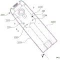
图5为本实用新型一实施例的污水箱的结构示意图;Fig. 5 is a schematic structural view of a waste water tank according to an embodiment of the present invention;

图6为图5所示的污水箱的内部结构示意图;Fig. 6 is a schematic diagram of the internal structure of the sewage tank shown in Fig. 5;

图7为图5所示的污水箱在正常使用状态下的结构示意图;Fig. 7 is a schematic structural view of the waste water tank shown in Fig. 5 in normal use;

图8为图5所示的污水箱在侧倾状态下的结构示意图。Fig. 8 is a schematic structural view of the waste water tank shown in Fig. 5 in a tilted state.

附图标号说明:10、底盘;20、机身;21、主体;211、杆体;2111、走线通道;2112、穿孔;212、接触件;22、水箱;221、清水箱;222、污水箱;2221、箱体;2222、第一侧壁;2223、第二侧壁;2224、第三侧壁;223、水位检测件;2231、第一水位检测件;2232、第二水位检测件;2233、第三水位检测件;2234、第四水位检测件;23、水管;231、出水端;24、操作部;25、抽风机。Description of reference numerals: 10, chassis; 20, fuselage; 21, main body; 211, rod body; 2111, wiring channel; 2112, perforation; 212, contact piece; 22, water tank; 221, clean water tank; 222, sewage tank 2221, box body; 2222, first side wall; 2223, second side wall; 2224, third side wall; 223, water level detection part; 2231, first water level detection part; 2232, second water level detection part; 2233 , the third water level detection part; 2234, the fourth water level detection part; 23, the water pipe; 231, the water outlet; 24, the operation part; 25, the exhaust fan.

具体实施方式Detailed ways

为使本实用新型的上述目的、特征和优点能够更加明显易懂,下面结合附图对本实用新型的具体实施方式做详细的说明。在下面的描述中阐述了很多具体细节以便于充分理解本实用新型。但是本实用新型能够以很多不同于在此描述的其它方式来实施,本领域技术人员可以在不违背本实用新型内涵的情况下做类似改进,因此本实用新型不受下面公开的具体实施例的限制。In order to make the above purpose, features and advantages of the present utility model more obvious and understandable, the specific implementation of the present utility model will be described in detail below in conjunction with the accompanying drawings. In the following description, numerous specific details are set forth in order to provide a full understanding of the present invention. However, the utility model can be implemented in many other ways different from those described here, and those skilled in the art can make similar improvements without violating the connotation of the utility model, so the utility model is not limited by the specific embodiments disclosed below limit.

请参阅图1、图2、图3和图5,本实用新型一实施例的洗地机,包括底盘10以及与所述底盘10铰接的机身20。底盘10包括底盘本体和设置于所述底盘本体上的电池件。机身20包括主体21和可拆卸安装于所述主体21的水箱22,主体21包括杆体211和设置于所述杆体211上的接触件212,接触件212包括第一接触端,所述杆体211内设有走线通道2111,所述第一接触端通过设置于所述走线通道2111内的第一连接线与所述电池件电连接。水箱22包括箱体2221和安装于所述箱体2221的水位检测件223,水位检测件223包括位于所述箱体2221内的检测端和位于所述箱体2221外侧壁的第二接触端。其中,当所述水箱22与所述主体21可拆卸连接时,所述第一接触端与所述第二接触端可以电接触。Referring to FIG. 1 , FIG. 2 , FIG. 3 and FIG. 5 , the floor washing machine according to an embodiment of the present invention includes a chassis 10 and a fuselage 20 hinged to the chassis 10 . The chassis 10 includes a chassis body and a battery component disposed on the chassis body. The fuselage 20 includes a main body 21 and a water tank 22 detachably mounted on the main body 21. The main body 21 includes a rod body 211 and a contact piece 212 arranged on the rod body 211. The contact piece 212 includes a first contact end. The rod body 211 A routing channel 2111 is provided inside, and the first contact end is electrically connected to the battery element through a first connecting wire arranged in the routing channel 2111 . The water tank 22 includes a box body 2221 and a water level detection member 223 mounted on the box body 2221 . The water level detection member 223 includes a detection end inside the box body 2221 and a second contact end on the outer wall of the box body 2221 . Wherein, when the water tank 22 is detachably connected to the main body 21, the first contact end and the second contact end can be in electrical contact.

上述洗地机,第一接触件212通过设置于走线通道2111内的第一连接线与电池件电连接,水箱22安装到主体21后,第一接触端和第二接触端电接触,这样电池件可为水位检测件223提供所需的电能,水位检测件223便能够检测水箱22内的水位。如此,将水位检测件223安装于箱体2221上,当水箱22和主体21可拆卸连接时,水位检测件223的第二接触端与接触件212的第一接触端有效接触,用以检测水箱22内的水位,有利于提高检测精度。In the above-mentioned washing machine, the first contact 212 is electrically connected to the battery through the first connection wire arranged in the wiring channel 2111, and after the water tank 22 is installed on the main body 21, the first contact end and the second contact end are in electrical contact, thus The battery can provide the required electric energy for the water level detection part 223 , and the water level detection part 223 can detect the water level in the water tank 22 . In this way, the water level detection part 223 is installed on the box body 2221. When the water tank 22 and the main body 21 are detachably connected, the second contact end of the water level detection part 223 is in effective contact with the first contact end of the contact part 212 to detect the water tank. The water level within 22 is conducive to improving the detection accuracy.

可选的,水位检测件223可以为市面上常见的接触式水位检测传感器,这里不做限定。Optionally, the water level detection member 223 may be a common contact water level detection sensor on the market, which is not limited here.

可选地,第一接触端和第二接触端中的其中一个为弹性接触柱,另外一个为接触板。可以理解的是,第一接触端为弹性接触柱,第二接触端为接触板;或者,第一接触端为接触板,第二接触板为弹性接触柱。如此,有利于第一接触端和第二接触端紧密接触,保证水位检测件223的检测功能。在其他实施例中,也可以是第一接触端和第二接触端均为弹性接触件,这里不做限定。Optionally, one of the first contact end and the second contact end is an elastic contact post, and the other is a contact plate. It can be understood that the first contact end is an elastic contact post, and the second contact end is a contact plate; or, the first contact end is a contact plate, and the second contact plate is an elastic contact post. In this way, it is beneficial for the close contact between the first contact end and the second contact end to ensure the detection function of the water level detection member 223 . In other embodiments, both the first contact end and the second contact end may be elastic contact members, which is not limited here.

在一个实施例中,图2、图3和图4,杆体211的侧壁上设置有连通所述走线通道2111的穿孔2112或者穿槽,所述第一接触端通过穿设于所述穿孔2112或者穿槽的第二连接线与所述第一连接线连接。如此,通过穿设于穿孔2112或者穿槽的第二连接线,方便连接第一接触端和第一连接线,进而实现第一接触端和电池件的电连接。In one embodiment, as shown in Fig. 2, Fig. 3 and Fig. 4, the side wall of the rod body 211 is provided with a through hole 2112 or a through groove communicating with the wiring channel 2111, and the first contact end passes through the through hole 2112 or the second connection line through the slot is connected to the first connection line. In this way, the first contact end and the first connection wire are conveniently connected through the second connection wire passing through the through hole 2112 or the slot, thereby realizing the electrical connection between the first contact end and the battery element.

在一个实施例中,参阅图1、图2和图3,水箱22包括污水箱222和清水箱221,所述污水箱222和清水箱221围合形成容置接触件212的容置空间。如此,可将接触件212收容于污水箱222和清水箱221围合形成的容置空间内。In one embodiment, referring to FIG. 1 , FIG. 2 and FIG. 3 , the water tank 22 includes a dirty water tank 222 and a fresh water tank 221 , and the dirty water tank 222 and the clean water tank 221 enclose to form an accommodating space for accommodating the contact member 212 . In this way, the contact element 212 can be accommodated in the accommodating space enclosed by the dirty water tank 222 and the clean water tank 221 .

在一个可选实施例中,其水箱22具体可以是污水箱222或清水箱221。In an optional embodiment, the water tank 22 may specifically be a sewage tank 222 or a clean water tank 221 .

在可选实施例中,具体可以是污水箱222包括箱体2221和水位检测件223,和/或清水箱221包括箱体2221和水位检测件223,即箱体2221和水位监测件223具体可以是污水箱222的,也可以是清水箱221。In an optional embodiment, specifically, the sewage tank 222 may include a tank body 2221 and a water level detection part 223, and/or the fresh water tank 221 may include a tank body 2221 and a water level detection part 223, that is, the tank body 2221 and the water level detection part 223 may specifically Be sewage tank 222, also can be clean water tank 221.

下述实施例中具体以污水箱222为例进行描述,其污水箱222包括有箱体2221和水位检测件223,如果无其他特别说明,下述出现的水箱22也具体是指污水箱222。可选地,接触件212上还设置有第一磁吸件,所述污水箱222和/或所述清水箱221设置有第二磁吸件,所述污水箱222和/或所述清水箱221通过所述第一磁吸件和所述第二磁吸件的配合可拆卸安装于接触件212上。如此设置,实现接触件212和污水箱222的可拆卸连接;和/或,实现接触件212和清水箱221的可拆卸连接。当然,在其它实施例中,也可采用扣合的方式实现接触件212、与污水箱222和/或清水箱221的可拆卸连接。In the following embodiments, the sewage tank 222 is used as an example for description. The sewage tank 222 includes a tank body 2221 and a water level detection part 223. Unless otherwise specified, the water tank 22 below also specifically refers to the sewage tank 222. Optionally, a first magnetic attraction is also provided on the contact member 212, a second magnetic attraction is provided on the sewage tank 222 and/or the clean water tank 221, and the sewage tank 222 and/or the clean water tank 221 is detachably mounted on the contact piece 212 through cooperation of the first magnetic attraction piece and the second magnetic attraction piece. With such arrangement, the detachable connection between the contact piece 212 and the dirty water tank 222 is realized; and/or, the detachable connection between the contact piece 212 and the fresh water tank 221 is realized. Of course, in other embodiments, the detachable connection between the contact member 212 and the dirty water tank 222 and/or the clean water tank 221 may also be realized by snap-fitting.

在一个实施例中,参阅图1和图2,机身20还包括设置于所述杆体211远离所述底盘10一端的操作部24。所述杆体211靠近所述操作部24的一端上设置有端部通孔,所述操作部24通过穿设于所述端部通孔和所述走线通道2111的第三连接线与所述电池件电连接。其中,所述第一接触端通过第四连接线与所述操作部24电连接,并进一步和与所述操作部24连接的所述第一连接线电连接。如此,通过穿设于端部通孔和走线通道2111的第三连接线,可实现操作部24和电池件的电连接,这样电池件可为操作部24提供所需的电能。In one embodiment, referring to FIG. 1 and FIG. 2 , the fuselage 20 further includes an operating portion 24 disposed at an end of the rod body 211 away from the chassis 10 . One end of the rod body 211 close to the operating portion 24 is provided with an end through hole, and the operating portion 24 connects to the The battery pack is electrically connected. Wherein, the first contact end is electrically connected to the operation part 24 through a fourth connection line, and is further electrically connected to the first connection line connected to the operation part 24 . In this way, the electrical connection between the operation part 24 and the battery can be realized through the third connecting wire passing through the end through hole and the wiring channel 2111 , so that the battery can provide the operation part 24 with required electric energy.

可选的,操作部24上设置有转接板和屏幕,其第一接触端通过第四连接线与操作部24的转接板电连接,随后才与电池件连接,可以有效的减少布线的复杂性。在一个实施例中,参阅图1和图2,所述机身20还包括设置于所述杆体211靠近所述底盘10一端的抽风机25。所述杆体211内还包括与所述走线通道2111并行设置的走气通道,所述抽风机25通过所述走气通道与所述水箱22连通。如此,通过抽风机25可以在水箱22内形成负压。Optionally, an adapter board and a screen are arranged on the operation part 24, and the first contact end thereof is electrically connected to the adapter board of the operation part 24 through a fourth connecting wire, and then connected to the battery, which can effectively reduce wiring Complexity. In one embodiment, referring to FIG. 1 and FIG. 2 , the fuselage 20 further includes an exhaust fan 25 disposed at an end of the rod body 211 close to the chassis 10 . The rod body 211 also includes an air outlet channel parallel to the cable channel 2111 , and the suction fan 25 communicates with the water tank 22 through the air outlet channel. In this way, negative pressure can be formed in the water tank 22 by the suction fan 25 .

在一个实施例中,参阅图1、图2和图5,水箱22还包括水管23,水管23包括出水端231,出水端231设于箱体2221内。箱体2221包括与机身20连接配合的第一侧壁2222、以及分别设于第一侧壁2222相对两侧的第二侧壁2223和第三侧壁2224,水位检测件223安装于第一侧壁2222,水位检测件223不超过出水端231的高度,水位检测件223用于检测箱体2221在第一侧壁2222相对洗地机的行进方向倾斜时是否水满、以及箱体2221在第二侧壁2223和第三侧壁2224相对洗地机的行进方向倾斜时是否倾斜过度。为了方便理解,参阅图图1和图7,采用S表示洗地机的行进方向。In one embodiment, referring to FIG. 1 , FIG. 2 and FIG. 5 , the water tank 22 further includes a water pipe 23 , the water pipe 23 includes a water outlet 231 , and the water outlet 231 is disposed in the tank body 2221 . The box body 2221 includes a first side wall 2222 connected and matched with the fuselage 20, and a second side wall 2223 and a third side wall 2224 respectively arranged on opposite sides of the first side wall 2222. The water level detection member 223 is installed on the first The side wall 2222, the water level detection part 223 does not exceed the height of the water outlet 231, the water level detection part 223 is used to detect whether the box body 2221 is full of water when the first side wall 2222 is inclined relative to the direction of travel of the washing machine, and the box body 2221 is in the Whether the second side wall 2223 and the third side wall 2224 are inclined excessively when they are inclined relative to the traveling direction of the scrubber. For the convenience of understanding, referring to Fig. 1 and Fig. 7, S is used to indicate the traveling direction of the washing machine.

在可选实施例中,洗地机还包括设置于底盘10上的吸水扒,水管23是用于连接吸水扒,从而通过吸水扒从地面收集污水,并从出水端231进入到污水箱。在另一可选实施例中,水管23也可以是用于连接走气通道的,从而通过出水端231抽吸箱体2221内的气流,并可以在箱体2221内形成负压,这里均不作限定。In an optional embodiment, the floor washing machine further includes a squeegee disposed on the chassis 10, and the water pipe 23 is used to connect the squeegee, so that the sewage is collected from the ground through the squeegee, and enters the waste water tank from the water outlet 231. In another optional embodiment, the water pipe 23 can also be used to connect the air outlet channel, so that the airflow in the box body 2221 can be sucked through the water outlet 231, and a negative pressure can be formed in the box body 2221, which is not described here. limited.

在可选实施例中,箱体2221在第二侧壁2223和第三侧壁2224相对洗地机的行进方向倾斜具体可以是在与行进方向所在的垂直平面内上下倾斜,也可以是相对行进方向进行翻转倾斜,即箱体2221相对行进方向会有侧倾,也可以是箱体在与行进方向所在的垂直平面内上下倾斜以及相对行进方向进行翻转倾斜综合倾斜。In an optional embodiment, the second side wall 2223 and the third side wall 2224 of the box body 2221 are inclined relative to the traveling direction of the washing machine. Specifically, it can be inclined up and down in a plane perpendicular to the traveling direction, or it can be relatively traveling. The direction is flipped and tilted, that is, the box body 2221 has a side tilt relative to the direction of travel, or the box body can be tilted up and down in a plane perpendicular to the direction of travel and comprehensively tilted by flipping and tilting relative to the direction of travel.

在可选实施例中,机身20可以是通过弹簧、球铰或者万向轴等多双自由度或多自由度的铰接件与底盘10实现铰接,因此机身20可以实现多个方向的扭转,并带动箱体2221实现多个方向的倾斜。In an optional embodiment, the fuselage 20 can be articulated with the chassis 10 through multiple double-degree-of-freedom or multi-degree-of-freedom hinges such as springs, ball joints, or cardan shafts, so that the fuselage 20 can be twisted in multiple directions. , and drive the box body 2221 to realize tilting in multiple directions.

使用时,将箱体2221安装到洗地机的杆体211上,即箱体2221的第一侧壁2222与杆体211连接配合,第一接触端与第二接触端电接触。洗地机在正常使用状态下,箱体2221的第一侧壁2222相对洗地机的行进方向倾斜设置,地面的污水被吸入水管23,并从水管23的出水端231排至箱体2221内,导致箱体2221内的水位不断增加。当箱体2221内的水位没过水位检测件223的部分检测端或者全部检测端时,检测端经过水介质发生导通,根据水位检测件223的检测信号判断箱体2221在第一侧壁2222相对洗地机的行进方向倾斜时已水满。洗地机在使用的过程中,若箱体2221的第二侧壁2223和第三侧壁2224相对洗地机的行进方向发生倾斜,当倾斜后箱体2221内的水位上升至没过水位检测件223的部分检测端时,检测端经过水介质发生导通,根据水位检测件223的检测信号得出箱体2221倾斜过度,这样用户可将洗地机回位到正常使用状态(或者关闭抽风机25),避免箱体2221内的水出现回流等异常情况或者水溢流到抽吸风机的情况。When in use, the box body 2221 is installed on the rod body 211 of the floor washing machine, that is, the first side wall 2222 of the box body 2221 is connected and matched with the rod body 211, and the first contact end is in electrical contact with the second contact end. When the floor washing machine is in normal use, the first side wall 2222 of the box body 2221 is arranged obliquely relative to the traveling direction of the floor washing machine, and the sewage on the ground is sucked into the water pipe 23 and discharged into the box body 2221 from the outlet end 231 of the water pipe 23 , causing the water level in the tank 2221 to continuously increase. When the water level in the box body 2221 is below some or all of the detection ends of the water level detection part 223, the detection end is conducted through the water medium, and according to the detection signal of the water level detection part 223, it is judged that the case body 2221 is on the first side wall 2222 It is full of water when it is inclined relative to the direction of travel of the scrubber. During the use of the washing machine, if the second side wall 2223 and the third side wall 2224 of the box body 2221 are tilted relative to the traveling direction of the washing machine, the water level in the box body 2221 rises to the point where the water level is not detected after the tilt. When part of the detection end of the part 223, the detection end passes through the water medium and conducts, and according to the detection signal of the water level detection part 223, it is obtained that the tank 2221 is tilted too much, so that the user can return the washing machine to the normal use state (or turn off the ventilation machine 25), to avoid abnormal situations such as backflow of water in the casing 2221 or water overflowing to the suction fan.

在一个实施例中,参阅图7和图8,当箱体2221内的水达到预设水容量且第一侧壁2222相对洗地机的行进方向呈预设角度设置时,箱体2221内的水面与第一侧壁2222的相交线为第一虚拟线。需要说明的是第一虚拟线是基于预设角度设置的,其中预设角度是为了防止洗地机倾斜过度而设置的角度,例如预设角度可为30°、45°、60°或者其它角度,在此不做具体限定;当第一侧壁2222相对洗地机的行进方向呈预设角度时,则箱体2221内的水会被一个或多个水位检测件223所检测到。水位检测件223设有至少三个,至少两个水位检测件223关于水管23的轴线对称设置,并设于第一虚拟线与出水端231所在水平线之间。上述至少两个水位检测件223的下方设有至少一个水位检测件223。如此,通过三个以上的水位检测件223不仅能够检测箱体2221在第一侧壁2222相对洗地机的行进方向倾斜时是否水满,还能够检测箱体2221在第二侧壁2223和第三侧壁2224相对洗地机的行进方向倾斜时是否倾斜过度。In one embodiment, referring to FIG. 7 and FIG. 8, when the water in the box body 2221 reaches a preset water capacity and the first side wall 2222 is set at a preset angle relative to the direction of travel of the washing machine, the water in the box body 2221 The intersection line between the water surface and the first side wall 2222 is a first imaginary line. It should be noted that the first virtual line is set based on a preset angle, where the preset angle is an angle set to prevent the floor scrubber from tilting excessively, for example, the preset angle can be 30°, 45°, 60° or other angles , not specifically limited here; when the first side wall 2222 is at a preset angle relative to the traveling direction of the washing machine, the water in the box body 2221 will be detected by one or more water level detection elements 223 . There are at least three water level detection parts 223, and at least two water level detection parts 223 are arranged symmetrically with respect to the axis of the water pipe 23, and are arranged between the first imaginary line and the horizontal line where the water outlet 231 is located. At least one water level detection member 223 is disposed below the at least two water level detection members 223 . In this way, more than three water level detection members 223 can not only detect whether the tank body 2221 is full of water when the first side wall 2222 is inclined relative to the moving direction of the scrubber, but also detect whether the tank body 2221 is full of water when the second side wall 2223 and the second side wall 2223 and the first side wall 2222 are tilted. Whether the three side walls 2224 are inclined excessively when they are inclined relative to the traveling direction of the washing machine.

为了方便理解,采用l1表示第一虚拟线,l4表示出水端231所在水平线,θ可以表示预设角度。For the convenience of understanding, l1 is used to represent the first imaginary line, l4 is used to represent the horizontal line where the water outlet 231 is located, and θ may represent a preset angle.

在其他实施例中,预设角度还可以是箱体2221其他的倾斜角度,如上下倾斜角度、侧倾角度或者上下倾斜角度和侧倾角度综合的倾斜角度或者其他多自由度角度倾斜的倾斜角度,这里不做限定。In other embodiments, the preset angle can also be other inclination angles of the box body 2221, such as up and down inclination angles, side inclination angles, or a combination of up and down inclination angles and side inclination angles, or inclination angles of other multi-degree-of-freedom angles , there is no limitation here.

可选地,水位检测件223为电极,电极为不锈钢或钛合金,电极通过注塑或其它方式焊接于箱体2221的第一侧壁2222。Optionally, the water level detection part 223 is an electrode, the electrode is stainless steel or titanium alloy, and the electrode is welded to the first side wall 2222 of the box body 2221 by injection molding or other methods.

在一个实施例中,当箱体2221内的水达到预设水容量且第二侧壁2223相对洗地机的行进方向呈预设角度设置时,箱体2221内的水面与第一侧壁2222的相交线为第二虚拟线。当箱体2221内的水达到预设水容量且第三侧壁2224相对洗地机的行进方向呈预设角度设置时,箱体2221内的水面与第一侧壁2222的相交线为第三虚拟线。需要说明的是,第二虚拟线和第三虚拟线均是基于预设角度设置的,其中预设角度是为了防止洗地机倾斜过度而设置的角度,例如预设角度可为30°、45°、60°或者其它角度,在此不做具体限定;当第二侧壁2223和第三侧壁2224相对洗地机的行进方向呈预设角度时,则水会被水位检测件223检测到。水位检测件223设有三个,分别为第一水位检测件2231、第二水位检测件2232和第三水位检测件2233。第一水位检测件2231和第二水位检测件2232均设于第一虚拟线上,第一水位检测件2231和第二水位检测件2232关于水管23的轴线对称设置(或者也是关于箱体2221的轴线对称设置)。第一水位检测件2231相对第二水位检测件2232靠近第二侧壁2223设置,第二水位检测件2232相对第一水位检测件2231靠近第三侧壁2224设置。第三水位检测件2233设于第一虚拟线远离出水端231的一侧,第三水位检测件2233设于第二虚拟线朝向第二侧壁2223一侧和第三虚拟线朝向第三侧壁2224一侧围成的区域内。洗地机在正常使用状态下,第一侧壁2222相对洗地机的行进方向倾斜设置,且当箱体2221内的水没过第一水位检测件2231、第二水位检测件2232和第三水位检测件2233的检测端时,第一水位检测件2231、第二水位检测件2232和第三水位检测件2233的检测端通过水介质发生导通,根据检测信号判断该箱体2221内的水已满。在使用的过程中,若第二侧壁2223相对洗地机的行进方向倾斜,且当箱体2221内的水没过第一水位检测件2231和第三水位检测件2233的检测端时,第一水位检测件2231和第三水位检测件2233的检测端通过水介质发生导通,根据检测信号判断箱体2221倾斜过度。若第三侧壁2224相对洗地机的行进方向倾斜,且当箱体2221内的水没过第二水位检测件2232和第三水位检测件2233的检测端时,第二水位检测件2232和第三水位检测件2233的检测端通过水介质发生导通,根据检测信号判断箱体2221倾斜过度。In one embodiment, when the water in the box body 2221 reaches a preset water capacity and the second side wall 2223 is set at a preset angle relative to the traveling direction of the washing machine, the water surface in the box body 2221 and the first side wall 2222 The intersection line of is the second virtual line. When the water in the box body 2221 reaches the preset water capacity and the third side wall 2224 is set at a preset angle relative to the direction of travel of the washing machine, the intersection line between the water surface in the box body 2221 and the first side wall 2222 is the third virtual line. It should be noted that both the second virtual line and the third virtual line are set based on a preset angle, wherein the preset angle is an angle set to prevent the floor scrubber from tilting excessively, for example, the preset angle can be 30°, 45° °, 60° or other angles, which are not specifically limited here; when the second side wall 2223 and the third side wall 2224 are at a preset angle relative to the direction of travel of the washing machine, the water will be detected by the water level detection member 223 . There are three water level detection parts 223 , namely a first water level detection part 2231 , a second water level detection part 2232 and a third water level detection part 2233 . The first water level detection part 2231 and the second water level detection part 2232 are all arranged on the first imaginary line, and the first water level detection part 2231 and the second water level detection part 2232 are arranged symmetrically about the axis of the water pipe 23 (or also about the box body 2221 Axisymmetric setting). The first water level detection member 2231 is disposed closer to the second side wall 2223 relative to the second water level detection member 2232 , and the second water level detection member 2232 is disposed closer to the third side wall 2224 relative to the first water level detection member 2231 . The third water level detection part 2233 is arranged on the side of the first imaginary line away from the water outlet 231, the third water level detection part 2233 is arranged on the side of the second imaginary line facing the second side wall 2223 and the third imaginary line is facing the third side wall 2224 within the area surrounded by one side. When the floor washing machine is in normal use, the first side wall 2222 is inclined relative to the direction of travel of the floor washing machine, and when the water in the box body 2221 has submerged the first water level detection part 2231, the second water level detection part 2232 and the third water level At the detection end of the detection part 2233, the detection ends of the first water level detection part 2231, the second water level detection part 2232 and the third water level detection part 2233 conduct through the water medium, and judge according to the detection signal that the water in the box body 2221 has Full. During use, if the second side wall 2223 is inclined relative to the traveling direction of the washing machine, and when the water in the box body 2221 has not passed the detection ends of the first water level detection part 2231 and the third water level detection part 2233, the first The detection ends of the water level detection part 2231 and the third water level detection part 2233 are connected through the water medium, and the tank 2221 is judged to be excessively tilted according to the detection signal. If the third side wall 2224 is inclined relative to the direction of progress of the washing machine, and when the water in the box body 2221 has not passed the detection ends of the second water level detection part 2232 and the third water level detection part 2233, the second water level detection part 2232 and the first water level detection part 2233 The detection end of the three water level detection parts 2233 is conducted through the water medium, and the tank 2221 is judged to be excessively tilted according to the detection signal.

为了方便理解,采用l2表示第二虚拟线,l3表示第三虚拟线。For easy understanding, l 2 is used to represent the second virtual line, and l 3 is used to represent the third virtual line.

在本实施例中,第一水位检测件2231设于第一虚拟线和第二虚拟线的交点位置,第二水位检测件2232设于第一虚拟线和第三虚拟线的交点位置,第三水位检测件2233设于第二虚拟线和第三虚拟线的交点位置。In this embodiment, the first water level detecting element 2231 is set at the intersection of the first imaginary line and the second imaginary line, the second water level detecting element 2232 is set at the intersection of the first imaginary line and the third imaginary line, and the third The water level detecting element 2233 is located at the intersection of the second imaginary line and the third imaginary line.

在另一个实施例中,参阅图5至图8,水位检测件223设有四个,分别为第一水位检测件2231、第二水位检测件2232、第三水位检测件2233和第四水位检测件2234。第一水位检测件2231相对第二水位检测件2232靠近第二侧壁2223设置,第二水位检测件2232相对第一水位检测件2231靠近第三侧壁2224设置;第三水位检测件2233相对第四水位检测件2234靠近第二侧壁2223设置,第四水位检测件2234相对第三水位检测件2233靠近第三侧壁2224设置。第一水位检测件2231和第二水位检测件2232设于第一虚拟线和出水端231所在水平线之间,并关于水管23的轴线对称(或者关于箱体2221的轴线对称设置)设置。第三水位检测件2233设于第二虚拟线朝向第二侧壁2223一侧的第一虚拟线上,第四水位检测件2234设于第三虚拟线朝向第三侧壁2224一侧的第一虚拟线上。洗地机在正常使用状态下,第一侧壁2222相对洗地机的行进方向倾斜设置,且当箱体2221内的水没过第三水位检测件2233和第四水位检测件2234的检测端时,第三水位检测件2233和第四水位检测件2234的检测端通过水介质发生导通,根据检测信号判断箱体2221内的水已满。在使用的过程中,若第二侧壁2223相对洗地机的行进方向倾斜,且当箱体2221内的水没过第一水位检测件2231和第三水位检测件2233的检测端时,第一水位检测件2231和第三水位检测件2233的检测端通过水介质发生导通,根据检测信号判断箱体2221倾斜过度。若第三侧壁2224相对洗地机的行进方向倾斜,且当箱体2221内的水没过第二水位检测件2232和第四水位检测件2234的检测端时,第二水位检测件2232和第四水位检测件2234的检测端通过水介质发生导通,根据检测信号判断箱体2221倾斜过度。In another embodiment, referring to Fig. 5 to Fig. 8, there are four water level detection parts 223, which are the first water level detection part 2231, the second water level detection part 2232, the third water level detection part 2233 and the fourth water level detection part. Part 2234. The first water level detection part 2231 is set close to the second side wall 2223 relative to the second water level detection part 2232, and the second water level detection part 2232 is set close to the third side wall 2224 relative to the first water level detection part 2231; The fourth water level detection part 2234 is disposed close to the second side wall 2223 , and the fourth water level detection part 2234 is disposed close to the third side wall 2224 relative to the third water level detection part 2233 . The first water level detection part 2231 and the second water level detection part 2232 are arranged between the first imaginary line and the horizontal line where the water outlet 231 is located, and are arranged symmetrically about the axis of the water pipe 23 (or arranged symmetrically about the axis of the tank 2221). The third water level detecting member 2233 is arranged on the first imaginary line on the side of the second imaginary line facing the second side wall 2223, and the fourth water level detecting member 2234 is arranged on the first imaginary line on the side of the third imaginary line facing the third side wall 2224. virtual online. When the floor washing machine is in normal use, the first side wall 2222 is inclined relative to the direction of travel of the floor washing machine, and when the water in the box body 2221 has not passed the detection ends of the third water level detection part 2233 and the fourth water level detection part 2234 , the detection ends of the third water level detection part 2233 and the fourth water level detection part 2234 are conducted through the water medium, and the water in the tank 2221 is judged to be full according to the detection signal. During use, if the second side wall 2223 is inclined relative to the traveling direction of the washing machine, and when the water in the box body 2221 has not passed the detection ends of the first water level detection part 2231 and the third water level detection part 2233, the first The detection ends of the water level detection part 2231 and the third water level detection part 2233 are connected through the water medium, and the tank 2221 is judged to be excessively tilted according to the detection signal. If the third side wall 2224 is inclined relative to the direction of progress of the washing machine, and when the water in the box body 2221 has not passed the detection ends of the second water level detection part 2232 and the fourth water level detection part 2234, the second water level detection part 2232 and the first water level detection part 2234 The detection ends of the four water level detection parts 2234 are conducted through the water medium, and the tank 2221 is judged to be excessively tilted according to the detection signal.

当然,在其它实施例中,第三水位检测件2233设于第二虚拟线朝向第二侧壁2223一侧的第一虚拟线上,第四水位检测件2234设于第一虚拟线的下方和第三虚拟线朝向第三侧壁2224的一侧围成的区域内。或者,第三水位检测件2233设于第一虚拟线的下方和第二虚拟线朝向第二侧壁2223的一侧围成的区域内,第四水位检测件2234设于第三虚拟线朝向第三侧壁2224一侧的第一虚拟线上。Certainly, in other embodiments, the third water level detecting member 2233 is arranged on the first imaginary line on the side of the second imaginary line facing the second side wall 2223, and the fourth water level detecting member 2234 is arranged below and below the first imaginary line. The third imaginary line faces the area enclosed by one side of the third side wall 2224 . Or, the third water level detection part 2233 is arranged in the area surrounded by the side below the first virtual line and the side of the second virtual line facing the second side wall 2223, and the fourth water level detection part 2234 is arranged on the third virtual line facing the second side wall 2223. The first imaginary line on one side of the three sidewalls 2224.

需要说明的是,当水位检测件223为五个以上时,可在四个水位检测件223的基础上增加一定数量的水位检测件223,在此不再赘述。It should be noted that, when there are more than five water level detection pieces 223, a certain number of water level detection pieces 223 can be added on the basis of four water level detection pieces 223, which will not be repeated here.

进一步地,参阅图5至图8,第一水位检测件2231和第三水位检测件2233错开设置,第二水位检测件2232和第四水位检测件2234错开设置。如此,可防止第一水位检测件2231和第二水位检测件2232上的水珠分别滴落到第三水位检测件2233和第四水位检测件2234的检测端,导致第三水位检测件2233和第四水位检测件2234的检测端导通而出现误判,提高检测准确性。Further, referring to FIG. 5 to FIG. 8 , the first water level detection part 2231 and the third water level detection part 2233 are staggered, and the second water level detection part 2232 and the fourth water level detection part 2234 are staggered. In this way, the water droplets on the first water level detection part 2231 and the second water level detection part 2232 can be prevented from dripping to the detection ends of the third water level detection part 2233 and the fourth water level detection part 2234 respectively, resulting in the third water level detection part 2233 and the fourth water level detection part 2234 The detection end of the fourth water level detection part 2234 is turned on and misjudgment occurs, which improves the detection accuracy.

可以理解的是,过第一水位检测件2231的垂线为第一垂线,过第二水位检测件2232的垂线为第二垂线。第三水位检测件2233和第四水位检测件2234均设于第一垂线和第二垂线之间,即将第一水位检测件2231、第二水位检测件2232、第四水位检测件2234和第三水位检测件2233依次连接形成倒梯形。或者,第三水位检测件2233设于第一垂线远离第二垂线的一侧,第四水位检测件2234设于第二垂线远离第一垂线的一侧,即第一水位检测件2231、第二水位检测件2232、第四水位检测件2234和第三水位检测件2233依次连接形成正梯形。It can be understood that the perpendicular line passing through the first water level detecting member 2231 is the first perpendicular line, and the perpendicular line passing through the second water level detecting member 2232 is the second perpendicular line. The third water level detection part 2233 and the fourth water level detection part 2234 are all arranged between the first vertical line and the second vertical line, that is, the first water level detection part 2231, the second water level detection part 2232, the fourth water level detection part 2234 and The third water level detection parts 2233 are connected in sequence to form an inverted trapezoid. Alternatively, the third water level detection part 2233 is set on the side where the first vertical line is away from the second vertical line, and the fourth water level detection part 2234 is set on the side where the second vertical line is away from the first vertical line, that is, the first water level detection part 2231 , the second water level detection part 2232 , the fourth water level detection part 2234 and the third water level detection part 2233 are sequentially connected to form a positive trapezoid.

在本实施例中,参阅图5至图8,第一水位检测件2231设于第二虚拟线和出水端231所在水平线的交点位置,第二水位检测件2232设于第三虚拟线和出水端231所在水平线的交点位置。第三水位检测件2233设于第一虚拟线和第二虚拟线的交点位置,第四水位检测件2234设于第一虚拟线和第三虚拟线的交点位置。In this embodiment, referring to Fig. 5 to Fig. 8, the first water level detection part 2231 is arranged at the intersection of the second imaginary line and the horizontal line where the water outlet 231 is located, and the second water level detection part 2232 is arranged at the third imaginary line and the water outlet. The intersection point of the horizontal line where 231 is located. The third water level detecting element 2233 is disposed at the intersection of the first imaginary line and the second imaginary line, and the fourth water level detecting element 2234 is disposed at the intersection of the first imaginary line and the third imaginary line.

在一个实施例中,洗地机还包括报警器和控制器,控制器分别与报警器和水位检测件223电连接。在洗地机使用的过程中,若控制器根据水位检测件223的检测信号判断箱体2221在第一侧壁2222相对洗地机的行进方向倾斜时已水满,则控制器控制报警器进行报警,提醒用户及时排出箱体2221内的水。若控制器根据水位检测件223的检测信号得出箱体2221倾斜过度,则控制器控制报警器进行报警,提醒用户将洗地机回位到正常使用状态,避免箱体2221内的水出现回流等异常情况。可选地,报警器可为语音提示器、振动器等,不以此为限。In one embodiment, the floor washing machine further includes an alarm and a controller, and the controller is electrically connected to the alarm and the water level detection member 223 respectively. During the use of the washing machine, if the controller judges that the tank body 2221 is full of water when the first side wall 2222 is inclined relative to the direction of travel of the washing machine according to the detection signal of the water level detection part 223, the controller controls the alarm. Alarm to remind the user to discharge the water in the box body 2221 in time. If the controller obtains that the tank 2221 is tilted excessively according to the detection signal of the water level detection part 223, the controller controls the alarm to give an alarm, reminding the user to return the washing machine to the normal use state, so as to avoid the backflow of water in the tank 2221 and other abnormal situations. Optionally, the alarm can be a voice prompter, a vibrator, etc., but is not limited thereto.

在本实用新型的描述中,需要理解的是,术语“中心”、“纵向”、“横向”、“长度”、“宽度”、“厚度”、“上”、“下”、“前”、“后”、“左”、“右”、“竖直”、“水平”、“顶”、“底”、“内”、“外”、“顺时针”、“逆时针”、“轴向”、“径向”、“周向”等指示的方位或位置关系为基于附图所示的方位或位置关系,仅是为了便于描述本实用新型和简化描述,而不是指示或暗示所指的装置或元件必须具有特定的方位、以特定的方位构造和操作,因此不能理解为对本实用新型的限制。In describing the present invention, it should be understood that the terms "center", "longitudinal", "transverse", "length", "width", "thickness", "upper", "lower", "front", "Back", "Left", "Right", "Vertical", "Horizontal", "Top", "Bottom", "Inner", "Outer", "Clockwise", "Counterclockwise", "Axial ", "radial", "circumferential" and other indicated orientations or positional relationships are based on the orientations or positional relationships shown in the drawings, and are only for the convenience of describing the utility model and simplifying the description, rather than indicating or implying No device or element must have a specific orientation, be constructed and operate in a specific orientation, and thus should not be construed as limiting the invention.

此外,术语“第一”、“第二”仅用于描述目的,而不能理解为指示或暗示相对重要性或者隐含指明所指示的技术特征的数量。由此,限定有“第一”、“第二”的特征可以明示或者隐含地包括至少一个该特征。在本实用新型的描述中,“多个”的含义是至少两个,例如两个,三个等,除非另有明确具体的限定。In addition, the terms "first" and "second" are used for descriptive purposes only, and cannot be interpreted as indicating or implying relative importance or implicitly specifying the quantity of indicated technical features. Thus, the features defined as "first" and "second" may explicitly or implicitly include at least one of these features. In the description of the present utility model, "plurality" means at least two, such as two, three, etc., unless otherwise specifically defined.

在本实用新型中,除非另有明确的规定和限定,术语“安装”、“相连”、“连接”、“固定”等术语应做广义理解,例如,可以是固定连接,也可以是可拆卸连接,或成一体;可以是机械连接,也可以是电连接;可以是直接相连,也可以通过中间媒介间接相连,可以是两个元件内部的连通或两个元件的相互作用关系,除非另有明确的限定。对于本领域的普通技术人员而言,可以根据具体情况理解上述术语在本实用新型中的具体含义。In this utility model, unless otherwise clearly specified and limited, the terms "installation", "connection", "connection", "fixation" and other terms should be understood in a broad sense, for example, it can be a fixed connection or a detachable connection. Connected, or integrated; may be mechanically or electrically connected; may be directly connected or indirectly connected through an intermediary, and may be an internal communication between two elements or an interactive relationship between two elements, unless otherwise stated Clearly defined. Those of ordinary skill in the art can understand the specific meanings of the above terms in the present utility model according to specific situations.

在本实用新型中,除非另有明确的规定和限定,第一特征在第二特征“上”或“下”可以是第一和第二特征直接接触,或第一和第二特征通过中间媒介间接接触。而且,第一特征在第二特征“之上”、“上方”和“上面”可是第一特征在第二特征正上方或斜上方,或仅仅表示第一特征水平高度高于第二特征。第一特征在第二特征“之下”、“下方”和“下面”可以是第一特征在第二特征正下方或斜下方,或仅仅表示第一特征水平高度小于第二特征。In the present invention, unless otherwise clearly specified and limited, the first feature may be in direct contact with the first feature or the first feature and the second feature through an intermediary indirect contact. Moreover, "above", "above" and "above" the first feature on the second feature may mean that the first feature is directly above or obliquely above the second feature, or simply means that the first feature is higher in level than the second feature. "Below", "beneath" and "beneath" the first feature may mean that the first feature is directly below or obliquely below the second feature, or simply means that the first feature is less horizontally than the second feature.

需要说明的是,当元件被称为“固定于”或“设置于”另一个元件,它可以直接在另一个元件上或者也可以存在居中的元件。当一个元件被认为是“连接”另一个元件,它可以是直接连接到另一个元件或者可能同时存在居中元件。本文所使用的术语“垂直的”、“水平的”、“上”、“下”、“左”、“右”和类似的表述只是为了说明的目的,并不表示是唯一的实施方式。It should be noted that when an element is referred to as being “fixed on” or “disposed on” another element, it may be directly on the other element or there may be an intervening element. When an element is referred to as being "connected to" another element, it can be directly connected to the other element or intervening elements may also be present. The terms "vertical", "horizontal", "upper", "lower", "left", "right" and similar expressions are used herein for purposes of illustration only and are not intended to represent the only embodiments.

以上所述实施例的各技术特征可以进行任意的组合,为使描述简洁,未对上述实施例中的各个技术特征所有可能的组合都进行描述,然而,只要这些技术特征的组合不存在矛盾,都应当认为是本说明书记载的范围。The technical features of the above-mentioned embodiments can be combined arbitrarily. To make the description concise, all possible combinations of the technical features in the above-mentioned embodiments are not described. However, as long as there is no contradiction in the combination of these technical features, should be considered as within the scope of this specification.

以上所述实施例仅表达了本实用新型的几种实施方式,其描述较为具体和详细,但并不能因此而理解为对实用新型专利范围的限制。应当指出的是,对于本领域的普通技术人员来说,在不脱离本实用新型构思的前提下,还可以做出若干变形和改进,这些都属于本实用新型的保护范围。因此,本实用新型专利的保护范围应以所附权利要求为准。The above-mentioned embodiments only express several implementation modes of the utility model, and the description thereof is relatively specific and detailed, but it should not be understood as limiting the scope of the utility model patent. It should be noted that those skilled in the art can make several modifications and improvements without departing from the concept of the present invention, and these all belong to the protection scope of the present invention. Therefore, the scope of protection of the utility model patent should be based on the appended claims.

Claims (13)

1.一种洗地机,其特征在于,所述洗地机包括底盘以及与所述底盘铰接的机身,所述机身包括主体和可拆卸安装于所述主体的水箱;1. A floor washing machine, characterized in that the floor washing machine comprises a chassis and a fuselage hinged to the chassis, and the fuselage comprises a main body and a water tank detachably mounted on the main body; 所述底盘包括底盘本体和设置于所述底盘本体上的电池件;The chassis includes a chassis body and a battery set on the chassis body; 所述主体包括杆体和设置于所述杆体上的接触件,所述接触件包括第一接触端,所述杆体内设有走线通道,所述第一接触端通过设置于所述走线通道内的第一连接线与所述电池件电连接;The main body includes a rod body and a contact piece arranged on the rod body, the contact piece includes a first contact end, a wiring channel is arranged in the rod body, and the first contact end is arranged on the wiring channel The first connecting wire inside is electrically connected to the battery; 所述水箱包括箱体和安装于所述箱体的水位检测件,所述水位检测件包括位于所述箱体内的检测端和位于所述箱体外侧壁的第二接触端;其中,当所述水箱与所述主体可拆卸连接时,所述第一接触端与所述第二接触端电接触。The water tank includes a box body and a water level detection part installed in the box body, the water level detection part includes a detection end located in the box body and a second contact end located on the outer wall of the box body; wherein, when the When the water tank is detachably connected to the main body, the first contact end is in electrical contact with the second contact end. 2.根据权利要求1所述的洗地机,其特征在于,所述杆体的侧壁上设置有连通所述走线通道的穿孔或者穿槽,所述第一接触端通过穿设于所述穿孔或者穿槽的第二连接线与所述第一连接线电连接。2. The washing machine according to claim 1, characterized in that, the side wall of the rod body is provided with a perforation or a groove communicating with the wiring channel, and the first contact end passes through the The second connecting wire through the hole or slot is electrically connected with the first connecting wire. 3.根据权利要求1所述的洗地机,其特征在于,所述机身还包括设置于所述杆体远离所述底盘一端的操作部,所述杆体靠近所述操作部的一端上设置有端部通孔,所述操作部通过穿设于所述端部通孔和所述走线通道的第三连接线与所述电池电连接;其中,所述第一接触端通过第四连接线与所述操作部连接,并通过所述操作部与所述第一连接线电连接。3. The floor washing machine according to claim 1, wherein the body further comprises an operation part arranged on the end of the rod body away from the chassis, and the end of the rod body close to the operation part is provided with An end through hole, the operating part is electrically connected to the battery through a third connecting wire passing through the end through hole and the wiring channel; wherein, the first contact end is connected through a fourth connecting wire It is connected with the operation part, and is electrically connected with the first connection line through the operation part. 4.根据权利要求1所述的洗地机,其特征在于,所述机身还包括设置于所述杆体靠近所述底盘一端的抽风机,所述杆体内还包括与所述走线通道并行设置的走气通道,所述抽风机通过所述走气通道与所述水箱连通。4. The floor washing machine according to claim 1, wherein the body further includes an exhaust fan arranged at one end of the rod body close to the chassis, and the rod body also includes an exhaust fan parallel to the wiring channel. An air outlet channel is provided, and the exhaust fan communicates with the water tank through the air outlet channel. 5.根据权利要求1所述的洗地机,其特征在于,所述第一接触端与第二接触端中的一个为弹性接触柱,另一个为接触板。5. The floor washing machine according to claim 1, wherein one of the first contact end and the second contact end is an elastic contact column, and the other is a contact plate. 6.根据权利要求1所述的洗地机,其特征在于,所述水箱包括污水箱和清水箱,所述污水箱和清水箱围合形成容置所述接触件的容置空间;6. The floor washing machine according to claim 1, wherein the water tank includes a sewage tank and a clean water tank, and the sewage tank and the clean water tank are enclosed to form an accommodating space for accommodating the contact member; 其中,所述接触件上还设置有第一磁吸件,所述污水箱和/或所述清水箱设置有第二磁吸件,所述污水箱和/或所述清水箱通过所述第一磁吸件和所述第二磁吸件的配合可拆卸安装于接触件上。Wherein, the contact member is also provided with a first magnetic attraction, the sewage tank and/or the clean water tank is provided with a second magnetic attraction, and the sewage tank and/or the clean water tank passes through the first magnetic attraction The cooperation between a magnetic attraction part and the second magnetic attraction part can be detachably installed on the contact part. 7.根据权利要求1至6任一项所述的洗地机,其特征在于,所述水箱还包括水管,所述水管包括出水端,所述出水端设于所述箱体内;所述箱体包括与所述机身连接配合的第一侧壁、以及分别设于所述第一侧壁相对两侧的第二侧壁和第三侧壁,所述水位检测件安装于所述第一侧壁,且所述水位检测件不超过所述出水端的高度,所述水位检测件用于检测所述箱体在所述第一侧壁相对洗地机的行进方向倾斜时是否水满、及所述箱体在所述第二侧壁和所述第三侧壁相对所述洗地机的行进方向倾斜时是否倾斜过度。7. The floor washing machine according to any one of claims 1 to 6, wherein the water tank further includes a water pipe, the water pipe includes a water outlet, and the water outlet is arranged in the box; the box The body includes a first side wall that is connected and matched with the fuselage, and a second side wall and a third side wall that are respectively arranged on opposite sides of the first side wall, and the water level detection member is installed on the first side wall. The side wall, and the water level detection part does not exceed the height of the water outlet, and the water level detection part is used to detect whether the tank is full of water when the first side wall is inclined relative to the direction of travel of the washing machine, and Whether the box is inclined excessively when the second side wall and the third side wall are inclined relative to the traveling direction of the scrubber. 8.根据权利要求7所述的洗地机,其特征在于,当所述箱体内的水达到预设水容量且所述第一侧壁相对洗地机的行进方向呈预设角度设置时,所述箱体内的水面与所述第一侧壁的相交线为第一虚拟线;8. The washing machine according to claim 7, wherein when the water in the box reaches a preset water capacity and the first side wall is set at a preset angle relative to the direction of travel of the washing machine, The intersection line between the water surface in the box and the first side wall is a first imaginary line; 所述水位检测件设有至少三个,至少两个所述水位检测件关于所述水管的轴线对称设置,并设于所述第一虚拟线与所述出水端所在水平线之间,所述至少两个水位检测件的下方设有至少一个所述水位检测件。There are at least three water level detection parts, and at least two of the water level detection parts are arranged symmetrically with respect to the axis of the water pipe, and are arranged between the first imaginary line and the horizontal line where the water outlet is located. At least one of the water level detection parts is arranged below the two water level detection parts. 9.根据权利要求8所述的洗地机,其特征在于,当所述箱体内的水达到预设水容量且所述第二侧壁相对洗地机的行进方向呈预设角度设置时,所述箱体内的水面与所述第一侧壁的相交线为第二虚拟线;当所述箱体内的水达到预设水容量且所述第三侧壁相对洗地机的行进方向呈预设角度设置时,所述箱体内的水面与所述第一侧壁的相交线为第三虚拟线;9. The washing machine according to claim 8, characterized in that, when the water in the box reaches a preset water capacity and the second side wall is set at a preset angle relative to the direction of travel of the washing machine, The intersection line between the water surface in the box and the first side wall is a second virtual line; when the water in the box reaches a preset water capacity and the third side wall is in a preset direction relative to the washing machine When the angle is set, the intersection line between the water surface in the box and the first side wall is the third imaginary line; 所述水位检测件设有三个,分别为第一水位检测件、第二水位检测件及第三水位检测件,所述第一水位检测件和所述第二水位检测件均设于所述第一虚拟线上,所述第一水位检测件和所述第二水位检测件关于所述水管的轴线对称设置,所述第一水位检测件相对所述第二水位检测件靠近所述第二侧壁设置,所述第二水位检测件相对所述第一水位检测件靠近所述第三侧壁设置,所述第三水位检测件设于所述第一虚拟线远离所述出水端的一侧,所述第三水位检测件设于所述第二虚拟线朝向所述第二侧壁一侧和所述第三虚拟线朝向所述第三侧壁一侧围成的区域内。There are three water level detection parts, which are the first water level detection part, the second water level detection part and the third water level detection part, and the first water level detection part and the second water level detection part are both arranged on the On a virtual line, the first water level detection part and the second water level detection part are arranged symmetrically with respect to the axis of the water pipe, and the first water level detection part is closer to the second side relative to the second water level detection part The second water level detection part is arranged on the third side wall relative to the first water level detection part, and the third water level detection part is arranged on the side of the first imaginary line away from the water outlet end, The third water level detection member is disposed in an area enclosed by the second imaginary line facing the second side wall and the third imaginary line facing the third side wall. 10.根据权利要求9所述的洗地机,其特征在于,所述第一水位检测件设于所述第一虚拟线和所述第二虚拟线的交点位置,所述第二水位检测件设于所述第一虚拟线和所述第三虚拟线的交点位置,所述第三水位检测件设于所述第二虚拟线和所述第三虚拟线的交点位置。10. The washing machine according to claim 9, characterized in that, the first water level detection part is set at the intersection of the first virtual line and the second virtual line, and the second water level detection part It is arranged at the intersection of the first imaginary line and the third imaginary line, and the third water level detection element is arranged at the intersection of the second imaginary line and the third imaginary line. 11.根据权利要求8所述的洗地机,其特征在于,当所述箱体内的水达到预设水容量且所述第二侧壁相对洗地机的行进方向呈预设角度设置时,所述箱体内的水面与所述第一侧壁的相交线为第二虚拟线;当所述箱体内的水达到预设水容量且所述第三侧壁相对洗地机的行进方向呈预设角度设置时,所述箱体内的水面与所述第一侧壁的相交线为第三虚拟线;11. The washing machine according to claim 8, characterized in that, when the water in the tank reaches a preset water capacity and the second side wall is set at a preset angle relative to the direction of travel of the washing machine, The intersection line between the water surface in the box and the first side wall is a second virtual line; when the water in the box reaches a preset water capacity and the third side wall is in a preset direction relative to the washing machine When the angle is set, the intersection line between the water surface in the box and the first side wall is the third imaginary line; 所述水位检测件设有四个,分别为第一水位检测件、第二水位检测件、第三水位检测件及第四水位检测件,所述第一水位检测件相对所述第二水位检测件靠近所述第二侧壁设置,所述第二水位检测件相对所述第一水位检测件靠近所述第三侧壁设置,所述第三水位检测件相对所述第四水位检测件靠近所述第二侧壁设置,所述第四水位检测件相对所述第三水位检测件靠近所述第三侧壁设置;所述第一水位检测件和所述第二水位检测件设于所述第一虚拟线和所述出水端所在水平线之间,并关于所述水管的轴线对称设置;所述第三水位检测件设于所述第二虚拟线朝向所述第二侧壁一侧的所述第一虚拟线上,所述第四水位检测件设于所述第三虚拟线朝向所述第三侧壁一侧的所述第一虚拟线上;或者,所述第三水位检测件设于所述第二虚拟线朝向所述第二侧壁一侧的所述第一虚拟线上,所述第四水位检测件设于所述第一虚拟线的下方和所述第三虚拟线朝向所述第三侧壁的一侧围成的区域内;或者,所述第三水位检测件设于所述第一虚拟线的下方和所述第二虚拟线朝向所述第二侧壁的一侧围成的区域内,所述第四水位检测件设于所述第三虚拟线朝向所述第三侧壁一侧的所述第一虚拟线上。There are four water level detection parts, which are the first water level detection part, the second water level detection part, the third water level detection part and the fourth water level detection part, and the first water level detection part is relative to the second water level detection part. The second water level detection part is set close to the second side wall, the second water level detection part is set close to the third side wall relative to the first water level detection part, and the third water level detection part is close to the fourth water level detection part The second side wall is set, and the fourth water level detection part is set close to the third side wall relative to the third water level detection part; the first water level detection part and the second water level detection part are set on the said third water level detection part between the first imaginary line and the horizontal line where the water outlet is located, and arranged symmetrically with respect to the axis of the water pipe; the third water level detection member is arranged on the side of the second imaginary line facing the second side wall On the first imaginary line, the fourth water level detecting member is arranged on the first imaginary line on the side of the third imaginary line facing the third side wall; or, the third water level detecting member It is arranged on the first imaginary line on the side of the second imaginary line facing the second side wall, and the fourth water level detection member is arranged below the first imaginary line and on the third imaginary line In the area enclosed by the side facing the third side wall; or, the third water level detection member is arranged below the first imaginary line and the second imaginary line faces the second side wall In an area enclosed by one side, the fourth water level detection member is arranged on the first imaginary line on the side of the third imaginary line facing the third side wall. 12.根据权利要求11所述的洗地机,其特征在于,所述第一水位检测件和所述第三水位检测件错开设置,所述第二水位检测件和所述第四水位检测件错开设置。12. The washing machine according to claim 11, characterized in that, the first water level detection part and the third water level detection part are staggered, and the second water level detection part and the fourth water level detection part Stagger settings. 13.根据权利要求11所述的洗地机,其特征在于,所述第一水位检测件设于所述第二虚拟线和所述出水端所在水平线的交点位置,所述第二水位检测件设于所述第三虚拟线和所述出水端所在水平线的交点位置,所述第三水位检测件设于所述第一虚拟线和所述第二虚拟线的交点位置,所述第四水位检测件设于所述第一虚拟线和所述第三虚拟线的交点位置。13. The washing machine according to claim 11, characterized in that, the first water level detection part is set at the intersection of the second imaginary line and the horizontal line where the water outlet is located, and the second water level detection part Set at the intersection of the third imaginary line and the horizontal line where the water outlet is located, the third water level detection element is located at the intersection of the first imaginary line and the second imaginary line, the fourth water level The detecting element is arranged at the intersection of the first imaginary line and the third imaginary line.
CN202223062000.3U 2022-11-18 2022-11-18 Washing machine Active CN219166301U (en)

Priority Applications (1)

Application Number Priority Date Filing Date Title
CN202223062000.3U CN219166301U (en) 2022-11-18 2022-11-18 Washing machine

Applications Claiming Priority (1)

Application Number Priority Date Filing Date Title
CN202223062000.3U CN219166301U (en) 2022-11-18 2022-11-18 Washing machine

Publications (1)

Publication Number Publication Date
CN219166301U true CN219166301U (en) 2023-06-13

Family

ID=86674954

Family Applications (1)

Application Number Title Priority Date Filing Date
CN202223062000.3U Active CN219166301U (en) 2022-11-18 2022-11-18 Washing machine

Country Status (1)

Country Link
CN (1) CN219166301U (en)

Similar Documents

Publication Publication Date Title
CN102920398A (en) Water-sucking type cleaner with water spraying function
WO2023272888A1 (en) Cleaning apparatus
CN113509116B (en) Surface cleaning system
CN118058667A (en) Sewage tank cover assembly, sewage tank, cleaning device and control method thereof
WO2025124305A1 (en) Wastewater tank of cleaning apparatus and cleaning apparatus
CN116687282A (en) cleaning equipment
CN114073453B (en) Sweeping robot
CN215457738U (en) Water tank of cleaning robot, cleaning robot and cleaning system
CN217610866U (en) Cleaning device and main machine thereof
WO2025140058A1 (en) Disinfection device and floor brush having same
CN218943226U (en) A surface cleaning device with good user experience
CN217447619U (en) Floor cleaning machine
CN211528421U (en) External liquid supply device
CN212234310U (en) Portable and easy-to-clean wet and dry vacuum cleaner structure
CN218528629U (en) Cleaning robot
CN216933020U (en) Surface cleaning apparatus
CN213940632U (en) Sewage tank and ground cleaning equipment
CN222018235U (en) A sterilizing device and a floor brush having the same
CN115628546A (en) An air conditioning drainage pump based on parallel plate capacitors for liquid level monitoring
CN114669562A (en) A pipeline cleaning tool
CN221711811U (en) Water tank assembly for cleaning equipment and cleaning equipment
CN219270777U (en) Suspended air inlet structure of hand-held cloth cleaner
CN116115138A (en) Water tank and surface cleaning equipment
CN218304726U (en) Cleaning equipment
CN223554782U (en) Charging dock and cleaning machine

Legal Events

Date Code Title Description
GR01 Patent grant
GR01 Patent grant
CP03 Change of name, title or address

Address after: 518051 Guangdong Province Shenzhen City Nanshan District Xili Street Xili Community Dashi Road Shenzhen International Innovation Valley Building 3 1101

Patentee after: Shenzhen Pudu Technology Co.,Ltd.

Country or region after: China

Address before: 518051 Guangdong Province Shenzhen City Nanshan District Xili Street Xili Community Dashi Road Shenzhen International Innovation Valley Building A 501

Patentee before: SHENZHEN PUDU TECHNOLOGY Co.,Ltd.

Country or region before: China

CP03 Change of name, title or address