CN219164838U - Chip mounter is used in electronic components equipment - Google Patents
Chip mounter is used in electronic components equipment Download PDFInfo
- Publication number
- CN219164838U CN219164838U CN202223052758.9U CN202223052758U CN219164838U CN 219164838 U CN219164838 U CN 219164838U CN 202223052758 U CN202223052758 U CN 202223052758U CN 219164838 U CN219164838 U CN 219164838U
- Authority
- CN
- China
- Prior art keywords
- chip mounter
- objective table
- rotating shaft
- rod
- supporting frame
- Prior art date
- Legal status (The legal status is an assumption and is not a legal conclusion. Google has not performed a legal analysis and makes no representation as to the accuracy of the status listed.)
- Active
Links
Images


Classifications
-
- Y—GENERAL TAGGING OF NEW TECHNOLOGICAL DEVELOPMENTS; GENERAL TAGGING OF CROSS-SECTIONAL TECHNOLOGIES SPANNING OVER SEVERAL SECTIONS OF THE IPC; TECHNICAL SUBJECTS COVERED BY FORMER USPC CROSS-REFERENCE ART COLLECTIONS [XRACs] AND DIGESTS
- Y02—TECHNOLOGIES OR APPLICATIONS FOR MITIGATION OR ADAPTATION AGAINST CLIMATE CHANGE
- Y02P—CLIMATE CHANGE MITIGATION TECHNOLOGIES IN THE PRODUCTION OR PROCESSING OF GOODS
- Y02P70/00—Climate change mitigation technologies in the production process for final industrial or consumer products
- Y02P70/50—Manufacturing or production processes characterised by the final manufactured product
Abstract
The utility model discloses a chip mounter for assembling electronic components, which comprises an objective table, wherein a supporting frame is arranged at the top of the objective table, a driving motor is arranged at the left side of the supporting frame, a rotating shaft is movably arranged at the output end of the driving motor, a conveying belt is rotatably arranged at the outer side of the rotating shaft, a fixed plate is arranged at the top of the objective table, and clamping frames are arranged on opposite sides of the fixed plate.
Description
Technical Field
The utility model belongs to the technical field of chip mounters, and particularly relates to a chip mounter for electronic component assembly.
Background
Chip mounter: the surface mounting device is a device for accurately placing surface mounting components on a PCB bonding pad by moving a mounting head after being configured in a dispensing machine or a screen printing machine, is divided into a manual type device and a full-automatic type device, is used as a support type device in the field of electronic mounting, has the advantages of high mounting speed, high mounting precision and stable and reliable mounting quality, thoroughly changes the characteristics of labor-intensive enterprises in the field of mounting, greatly improves the production efficiency, liberates labor force and is an indispensable device in the modern mounting industry.
To sum up, the existing chip mounter is used as a pillar type device in the field of electronic mounting, and most of the chip mounter is difficult to compress and fix electronic components to be mounted when mounting, so that the components may shake and the like when mounting, thereby affecting the mounting quality of the device and bringing great inconvenience.
Disclosure of Invention
Aiming at the problems in the prior art, the utility model provides the chip mounter for electronic component assembly, which has the advantage of reliability, and solves the problems that the chip mounter is used as a strut type device in the field of electronic mounting, most of chip mounters are difficult to compress and fix electronic components to be mounted, so that the components can shake and the like when being mounted, thereby influencing the chip mounting quality of the device and bringing great inconvenience.
The utility model discloses a chip mounter for assembling electronic components, which comprises an objective table, wherein a supporting frame is arranged at the top of the objective table, a driving motor is arranged at the left side of the supporting frame, a rotating shaft is movably arranged at the output end of the driving motor, a conveying belt is rotatably arranged at the outer side of the rotating shaft, a fixing plate is arranged at the top of the objective table, a clamping frame is arranged on the opposite surface of the fixing plate, a first air cylinder is arranged at the upper side of the clamping frame, a movable rod is movably arranged at the bottom of the first air cylinder, a clamping plate is fixedly arranged at the bottom of the movable rod, a spring is sleeved at the outer side of the movable rod, a fixing rod is arranged at the upper side of the objective table, a connecting rod is connected at the upper side of the fixing rod, a mounting shell is detachably arranged at the upper side of the connecting rod, a second air cylinder is detachably arranged in the mounting shell, a telescopic rod is movably arranged at the bottom of the second air cylinder, a chip mounting head is arranged at the bottom of the telescopic rod, and a placing groove is arranged above the conveying belt.
In the present utility model, the number of the supporting frames is four, and the supporting frames are respectively arranged at four corners of the top of the stage.
Preferably, the rotating shaft penetrates through the right supporting frame, a bearing is mounted at the right end of the rotating shaft, and the bearing is arranged on the right side of the right supporting frame.
Preferably, the fixing plates are arranged at two sides of the conveyor belt.
Preferably, the fixing rod and the connecting rod are welded.
Preferably, the second cylinder is connected with the second cylinder by a fastening screw.
Compared with the prior art, the utility model has the following beneficial effects:
1. according to the utility model, the clamping frame, the first air cylinder, the movable rod, the clamping plate and the spring are matched, so that the electronic component is conveniently compressed during the pasting, the situation that the electronic component to be pasted is difficult to compress and fix during the pasting is avoided, the second air cylinder, the telescopic rod and the pasting head are matched, the time required by an operator to operate the device to clamp and fix the electronic component is shortened, the working efficiency of the operator is improved, and the production efficiency is greatly improved.
2. According to the utility model, the supporting frame is arranged, so that the conveying device can be positioned.
3. According to the utility model, the bearing is arranged, so that the rotating shaft is conveniently protected, and the phenomenon that the rotating shaft is inclined in the rotating process is prevented.
4. According to the utility model, the fixing plate is arranged, and the screw is used for mounting between the fixing plate and the objective table, so that the electronic component can be conveniently detached and adjusted, and the fixing plate is oppositely arranged, so that the electronic component can be conveniently clamped.
5. According to the utility model, the fixing rod and the connecting rod are welded, so that the chip mounter device can be supported conveniently, and the middle part of the chip mounter device right above the objective table is in a horizontal position.
6. According to the utility model, the mounting shell is connected with the second air cylinder, so that the diversity of the patch size of the device in use is enhanced, the applicability of the device in use is enhanced, and the use effect of an operator for manipulating the device to patch electronic components is improved.
Drawings
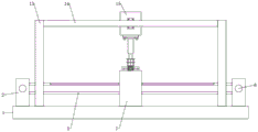
FIG. 1 is a schematic diagram of a structure provided by an embodiment of the present utility model;
FIG. 2 is a front view provided by an embodiment of the present utility model;
FIG. 3 is a schematic view of a clamping device according to an embodiment of the present utility model;
fig. 4 is a schematic diagram of a conveyor belt according to an embodiment of the present utility model.
In the figure: 1. an objective table; 2. a support frame; 3. a driving motor; 4. a rotating shaft; 5. a conveyor belt; 6. a bearing; 7. a fixing plate; 8. a clamping frame; 9. a first cylinder; 10. a movable rod; 11. a clamping plate; 12. a spring; 13. a fixed rod; 14. a connecting rod; 15. a mounting shell; 16. a second cylinder; 17. a telescopic rod; 18. a patch head; 19. and (5) placing a groove.
Detailed Description
For a further understanding of the utility model, its features and advantages, reference is now made to the following examples, which are illustrated in the accompanying drawings.
The structure of the present utility model will be described in detail with reference to the accompanying drawings.
As shown in fig. 1 to 4, the chip mounter for assembling electronic components provided by the embodiment of the utility model comprises an objective table 1, wherein a supporting frame 2 is installed at the top of the objective table 1, a driving motor 3 is installed at the left side of the supporting frame 2, a rotating shaft 4 is movably installed at the output end of the driving motor 3, a conveyor belt 5 is rotatably installed at the outer side of the rotating shaft 4, a fixing plate 7 is arranged at the top of the objective table 1, a clamping frame 8 is arranged on the opposite surface of the fixing plate 7, a first air cylinder 9 is arranged at the upper side of the clamping frame 8, a movable rod 10 is movably installed at the bottom of the first air cylinder 9, a clamping plate 11 is fixedly installed at the bottom of the movable rod 10, a spring 12 is sleeved at the outer side of the movable rod 10, a fixed rod 13 is arranged at the upper side of the objective table 1, a connecting rod 14 is connected at the upper side of the fixed rod 14, a mounting shell 15 is detachably installed at the upper side of the connecting rod 14, a second air cylinder 16 is detachably installed inside the mounting shell 15, a telescopic rod 17 is movably installed at the bottom of the second air cylinder 16, a mounting head 18 is installed at the bottom of the telescopic rod 17, and a placing groove 19 is arranged above the conveyor belt 5.
Referring to fig. 1 and 2, the number of the supporting frames 2 is four, and the supporting frames are respectively arranged at four corners of the top of the stage 1.
The scheme is adopted: by providing the support frame 2, the transmission device can be positioned.
Referring to fig. 1, a rotation shaft 4 penetrates through a right side support frame 2, a bearing 6 is mounted at the right end of the rotation shaft 4, and the bearing 6 is disposed on the right side of the right side support frame 2.
The scheme is adopted: through setting up bearing 6, be convenient for protect axis of rotation 4, prevent that axis of rotation 4 from appearing the phenomenon of slope at rotatory in-process.
Referring to fig. 1, 2 and 3, the fixing plates 7 are provided in two, respectively, on both sides of the conveyor belt 5.
The scheme is adopted: through setting up fixed plate 7, utilize the screw rod to install between fixed plate 7 and the objective table 1, can convenient to detach, the effect of being convenient for adjust, fixed plate 7 is the opposition setting, is convenient for carry out better centre gripping to electronic components.
Referring to fig. 1 and 2, the fixing rod 13 and the connecting rod 14 are provided for welding.
The scheme is adopted: through setting up dead lever 13 and connecting rod 14 for welded connection, can be convenient for advance the support to the chip mounter device for the chip mounter device is in the middle part directly over objective table 1 and is in horizontal position.
Referring to fig. 1 and 2, the mounting housing 15 and the second cylinder 16 are coupled by a fastening screw.
The scheme is adopted: through setting up the connection of installation casing 15 and second cylinder 16, strengthened the device paster size's when using diversity, strengthened the suitability of device when using, improved the result of use that operating personnel manipulated the device to carry out the paster to electronic components.
The working principle of the utility model is as follows:
when the patch machine is used, firstly, the external controller and the power supply are used, electronic elements are placed on the placing groove 19 above the conveyor belt 5 by a user, the driving motor 3 is started, the conveyor belt 5 on the rotating shaft 4 is driven by the driving motor 3 to rotate, the electronic elements on the upper side of the placing groove 19 are moved to the bottom of the clamping plate 11, so that the electronic elements are pressed, the first air cylinder 9 is started, the clamping plate 11 at the bottom of the movable rod 10 is driven to approach the electronic elements, after the positioning is finished, the second air cylinder 16 is started, the telescopic rod 17 is driven to move downwards, the patch head 18 moves downwards, then the patch treatment is started, the inconvenience that the elements possibly shake and the like when the patch machine is used for patch is reduced, the patch quality of the device is influenced, the automation degree of the manual patch machine is improved, and the working efficiency is also improved.
To sum up: according to the chip mounter for electronic component assembly, the object stage 1, the support frame 2, the driving motor 3, the rotating shaft 4, the conveyor belt 5, the bearing 6, the fixing plate 7, the clamping frame 8, the first air cylinder 9, the movable rod 10, the clamping plate 11, the spring 12, the fixing rod 13, the connecting rod 14, the mounting shell 15, the second air cylinder 16, the telescopic rod 17, the chip mounter 18 and the placing groove 19 are matched, so that the problem that the existing chip mounter is used as a support type device in the field of electronic mounting is solved, most of chip mounters are difficult to compress and fix electronic components to be mounted during mounting, shaking and the like possibly occur to the components during mounting, the chip mounting quality of the device is affected, and great inconvenience is caused.
It is noted that relational terms such as first and second, and the like are used solely to distinguish one entity or action from another entity or action without necessarily requiring or implying any actual such relationship or order between such entities or actions. Moreover, the terms "comprises," "comprising," or any other variation thereof, are intended to cover a non-exclusive inclusion, such that a process, method, article, or apparatus that comprises a list of elements does not include only those elements but may include other elements not expressly listed or inherent to such process, method, article, or apparatus.
Although embodiments of the present utility model have been shown and described, it will be understood by those skilled in the art that various changes, modifications, substitutions and alterations can be made therein without departing from the principles and spirit of the utility model, the scope of which is defined in the appended claims and their equivalents.
Claims (6)
1. The utility model provides an electron components and parts equipment is with chip mounter, includes objective table (1), its characterized in that: the utility model discloses a telescopic device for the telescopic device of the mobile device, which comprises a supporting frame (2) and is characterized in that the supporting frame (2) is arranged at the top of the objective table (1), a driving motor (3) is arranged at the left side of the supporting frame (2), a rotating shaft (4) is movably arranged at the output end of the driving motor (3), a conveying belt (5) is rotatably arranged at the outer side of the rotating shaft (4), a fixing plate (7) is arranged at the top of the objective table (1), a clamping frame (8) is arranged on the opposite surface of the fixing plate (7), a first air cylinder (9) is arranged at the upper side of the clamping frame (8), a movable rod (10) is movably arranged at the bottom of the first air cylinder (9), a clamping plate (11) is fixedly arranged at the bottom of the movable rod (10), a spring (12) is sleeved at the outer side of the movable rod (10), a fixing rod (13) is arranged at the upper side of the objective table (1), a connecting rod (14) is connected at the upper side of the fixing rod (13), a mounting shell (15) is detachably arranged at the upper side of the connecting rod (14), a second air cylinder (16) is detachably arranged at the upper side of the connecting rod (16), a telescopic device of the telescopic device is arranged at the bottom of the telescopic device (17), a placing groove (19) is formed above the conveyor belt (5).
2. The chip mounter for electronic component assembly according to claim 1, wherein: the number of the supporting frames (2) is four, and the supporting frames are respectively arranged at four corners of the top of the objective table (1).
3. The chip mounter for electronic component assembly according to claim 1, wherein: the rotating shaft (4) penetrates through the right side supporting frame (2), a bearing (6) is arranged at the right end of the rotating shaft (4), and the bearing (6) is arranged on the right side of the right side supporting frame (2).
4. The chip mounter for electronic component assembly according to claim 1, wherein: the two fixing plates (7) are respectively arranged at two sides of the conveyor belt (5).
5. The chip mounter for electronic component assembly according to claim 1, wherein: the fixing rod (13) and the connecting rod (14) are welded.
6. The chip mounter for electronic component assembly according to claim 1, wherein: the second cylinder (16) is connected with the second cylinder (15) by a fastening screw.
Priority Applications (1)
| Application Number | Priority Date | Filing Date | Title |
|---|---|---|---|
| CN202223052758.9U CN219164838U (en) | 2022-11-17 | 2022-11-17 | Chip mounter is used in electronic components equipment |
Applications Claiming Priority (1)
| Application Number | Priority Date | Filing Date | Title |
|---|---|---|---|
| CN202223052758.9U CN219164838U (en) | 2022-11-17 | 2022-11-17 | Chip mounter is used in electronic components equipment |
Publications (1)
| Publication Number | Publication Date |
|---|---|
| CN219164838U true CN219164838U (en) | 2023-06-09 |
Family
ID=86642142
Family Applications (1)
| Application Number | Title | Priority Date | Filing Date |
|---|---|---|---|
| CN202223052758.9U Active CN219164838U (en) | 2022-11-17 | 2022-11-17 | Chip mounter is used in electronic components equipment |
Country Status (1)
| Country | Link |
|---|---|
| CN (1) | CN219164838U (en) |
-
2022
- 2022-11-17 CN CN202223052758.9U patent/CN219164838U/en active Active
Similar Documents
| Publication | Publication Date | Title |
|---|---|---|
| CN101987387A (en) | Fully automatic novel electronic component soldering machine | |
| CN219164838U (en) | Chip mounter is used in electronic components equipment | |
| CN110202368B (en) | Assembling device and assembling method for connector | |
| CN207807066U (en) | Automatic screw subgroup assembling machine | |
| CN114427069B (en) | Borderless clamping equipment for tin spraying of circuit board | |
| CN212371557U (en) | CCD positioning and assembling equipment | |
| CN214922186U (en) | Bending and welding system for outer frame structural member of microwave oven | |
| CN212095125U (en) | Clamping piece assembling machine | |
| CN211804294U (en) | Reflow soldering clamp | |
| CN213497068U (en) | Clamping device for full-automatic soldering machine | |
| CN220445283U (en) | Vertical automatic tin spraying machine belt feeding and discharging machine | |
| CN110933869A (en) | Accurate equipment of counterpointing | |
| CN219726528U (en) | Punching device for PCB production | |
| CN110155676A (en) | Group screen device | |
| CN215946066U (en) | Visual positioning mobile phone accessory double-station pasting machine | |
| CN211890735U (en) | Assembly platform for internal drive electronic driver parts | |
| CN214212813U (en) | Steel sheet pastes dress equipment | |
| CN218072306U (en) | SMT paster anchor clamps | |
| CN208616835U (en) | A kind of bag making workshop rocker arm blanking machine | |
| CN214901472U (en) | Positioning-stable SMT (surface mount technology) paster carrier | |
| CN211457587U (en) | Novel automatic crest welder mechanical equipment | |
| CN216491295U (en) | PCB board rotary device | |
| CN220123160U (en) | Tensioning type PCB patch reflow soldering jig | |
| CN220441024U (en) | Wave crest welding fixture for circuit board components | |
| CN218695528U (en) | Welding tool for base station antenna oscillator component |
Legal Events
| Date | Code | Title | Description |
|---|---|---|---|
| GR01 | Patent grant | ||
| GR01 | Patent grant |