CN219141557U - Energy-saving cooling tower - Google Patents
Energy-saving cooling tower Download PDFInfo
- Publication number
- CN219141557U CN219141557U CN202221896717.5U CN202221896717U CN219141557U CN 219141557 U CN219141557 U CN 219141557U CN 202221896717 U CN202221896717 U CN 202221896717U CN 219141557 U CN219141557 U CN 219141557U
- Authority
- CN
- China
- Prior art keywords
- tower body
- condensing
- pipe
- energy
- cooling tower
- Prior art date
- Legal status (The legal status is an assumption and is not a legal conclusion. Google has not performed a legal analysis and makes no representation as to the accuracy of the status listed.)
- Active
Links
Images


Classifications
-
- Y—GENERAL TAGGING OF NEW TECHNOLOGICAL DEVELOPMENTS; GENERAL TAGGING OF CROSS-SECTIONAL TECHNOLOGIES SPANNING OVER SEVERAL SECTIONS OF THE IPC; TECHNICAL SUBJECTS COVERED BY FORMER USPC CROSS-REFERENCE ART COLLECTIONS [XRACs] AND DIGESTS
- Y02—TECHNOLOGIES OR APPLICATIONS FOR MITIGATION OR ADAPTATION AGAINST CLIMATE CHANGE
- Y02B—CLIMATE CHANGE MITIGATION TECHNOLOGIES RELATED TO BUILDINGS, e.g. HOUSING, HOUSE APPLIANCES OR RELATED END-USER APPLICATIONS
- Y02B30/00—Energy efficient heating, ventilation or air conditioning [HVAC]
- Y02B30/70—Efficient control or regulation technologies, e.g. for control of refrigerant flow, motor or heating
Landscapes
- Heat-Exchange Devices With Radiators And Conduit Assemblies (AREA)
Abstract
The utility model provides an energy-saving cooling tower, comprising: the solar cell module comprises a tower body and a solar cell module, wherein the solar cell module is arranged at the top end of the tower body; the tower body is provided with an air inlet and an air outlet in a penetrating manner in the lateral direction, an air supply system is arranged at the outer side of the air inlet, a condensing pipe is arranged in the tower body and close to the air outlet, an atomization mechanism is arranged in the tower body and below the condensing pipe, and a plurality of packing layers which are arranged at intervals up and down are arranged at the bottom end of the inner part of the tower body; the condenser pipe has a plurality of condensation channels that link to each other along the horizontal return pipe that transversely arranges and constitute, the inside equidistance interval of condensation channel is equipped with a plurality of return nozzles, the return nozzle is loudspeaker form, just the shrink direction of return nozzle and the flow direction reverse arrangement of condensing medium, the shrink end of return nozzle with form the choked flow clearance between the condenser pipe. Through the utility model, the utilization efficiency of the cooling medium is improved, and the effect of more energy conservation and environmental protection is realized.
Description
Technical Field
The utility model relates to the technical field of heat energy exchange, in particular to an energy-saving cooling tower.
Background
The cooling tower takes water as a circulating coolant, absorbs heat from the system and discharges the heat into the atmosphere to reduce the water temperature, the water is contacted with air in a flowing way to perform cold-heat exchange to generate steam, and the steam is volatilized to take away the heat to reach the principles of evaporation heat dissipation, convection heat transfer, radiation heat transfer and the like to dissipate the waste heat generated in the industry or refrigeration air conditioner to reduce the water temperature, so that the normal operation of the system is ensured.
The cooling tower in the prior art is generally arranged at the top of a building, basically a plurality of devices are combined, the cooling tower runs throughout the year, a large amount of electric power resources are consumed, huge cost pressure is brought to building management units, meanwhile, in order to solve the problem that the white fog phenomenon occurs at the heat discharging opening of the cooling tower, a condensation layer is arranged in the prior art, on one hand, the cooling tower prevents heat discharging efficiency, on the other hand, under the efficient working of the cooling tower, condensate in the condensation layer is poor in fluidity, the outer layer cooling efficiency of the condensation layer is low, mist condensation water drops cannot be caused, and the problem of successfully discharging white fog is solved.
In view of this, there is a need for an improved cooling tower structure in the prior art to solve the above-described problems.
Disclosure of Invention
The utility model aims to disclose an energy-saving cooling tower, which solves the problems that the condensation effect of fog is reduced due to insufficient utilization of cooling medium and over-high temperature of the outer side of a condensation pipe, white fog is discharged from the cooling tower, improves the cooling performance of the cooling tower, and is more energy-saving and environment-friendly.
To achieve the above object, the present utility model provides an energy-saving cooling tower comprising: the solar cell module comprises a tower body and a solar cell module, wherein the solar cell module is arranged at the top end of the tower body; the tower body is provided with an air inlet and an air outlet in a penetrating manner in the lateral direction, an air supply system is arranged at the outer side of the air inlet, a condensing pipe is arranged in the tower body and close to the air outlet, an atomization mechanism is arranged in the tower body and below the condensing pipe, a plurality of packing layers which are arranged at intervals up and down are arranged at the bottom end of the tower body, a water storage cavity is formed between the packing layers and the bottom end of the tower body, and a water pumping pipe communicated with the water storage cavity is arranged at the bottom of the tower body;
the condenser pipe has a plurality of condensation channels that link to each other along the horizontal return pipe that transversely arranges and constitute, the inside equidistance interval of condensation channel is equipped with a plurality of return nozzles, the return nozzle is loudspeaker form, just the shrink direction of return nozzle and the flow direction reverse arrangement of condensing medium, the shrink end of return nozzle with form the choked flow clearance between the condenser pipe.
As a further improvement of the utility model, the condensing channels are provided with a plurality of groups along the horizontal and longitudinal directions, and the outlet ends are communicated through connecting pipes, so that the condensing medium inflow opening and the condensing medium outflow opening of the condensing pipes are arranged on the same side.
As a further improvement of the utility model, a condensing medium tank and a pumping pump are also arranged outside the tower body.
As a further improvement of the utility model, a filtering interlayer is arranged inside the tower body and close to the air inlet and the air outlet.
As a further development of the utility model, the filler layer has a number of honeycomb channels inside.
As a further improvement of the utility model, the honeycomb channels are formed by surrounding adjacent filler sheets, and the filler sheets are made of PVC or PP nonmetallic materials.
As a further improvement of the utility model, the atomizing mechanism comprises a water inlet pipe which is horizontally and transversely arranged, and a plurality of atomizing nozzles which are arranged at the periphery of the water inlet pipe and are axially and alternately arranged.
Compared with the prior art, the utility model has the beneficial effects that:
(1) An energy-saving cooling tower can provide energy required by consumption for an air supply system by utilizing a solar cell module arranged at the top of the tower, so that the energy consumption is effectively saved; the inside at the condenser pipe is equipped with the horn-shaped backward flow mouth, and the shrink direction of backward flow mouth is reverse arrangement with the flow direction of condensing medium, form the choked flow clearance between shrink end and the condenser pipe of backward flow mouth for appear mixing in turn between the condensing medium that is located the inside sandwich layer of condensing passage and the outer condensing medium, the inside heat conduction of condensing passage has been aggravated, avoid under the high-efficient operation of cooling tower, the outer end heat of condenser pipe is linear conduction in condensing passage, thereby the utilization efficiency of condensing medium has been influenced, the efficiency of vapor condensation in the fog has been reduced, cause the cooling tower to appear white fog exhaust problem.
(2) The wind inlet and the wind outlet are formed in the lateral direction of the tower body, so that wind power in the nature can be effectively utilized, the efficient operation of the tower body is ensured, and the energy consumption of the air supply system is effectively reduced.
Drawings
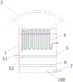
FIG. 1 is a schematic diagram of an energy-efficient cooling tower of the present utility model in a left perspective;
FIG. 2 is a schematic diagram of an energy-saving cooling tower according to the present utility model, wherein the air supply system is omitted;
fig. 3 is a schematic diagram of the positional relationship between a condensing tube and a return nozzle in an energy-saving cooling tower, and the flow direction of a condensing medium is shown in the figure.
In the figure: 1. a tower body; 2. a solar cell module; 3. an air supply system; 4. a condensing tube; 5. an atomizing mechanism; 6. a filler layer; 7. a water pumping pipe; 8. filtering the interlayer; 41. a return nozzle; 51. a water inlet pipe; 52. an atomizing nozzle; 100. a water storage chamber; 101. an air inlet; 102. and an air outlet.
Detailed Description
The present utility model will be described in detail below with reference to the embodiments shown in the drawings, but it should be understood that the embodiments are not limited to the present utility model, and functional, method, or structural equivalents and alternatives according to the embodiments are within the scope of protection of the present utility model by those skilled in the art.
It should be noted that, in the case of no conflict, the embodiments and features in the embodiments may be combined with each other.
In the description of the present application, it should be understood that the terms "center," "longitudinal," "transverse," "upper," "lower," "front," "rear," "left," "right," "vertical," "horizontal," "top," "bottom," "inner," "outer," and the like indicate orientations or positional relationships based on the orientations or positional relationships shown in the drawings, merely to facilitate description of the present application and simplify the description, and do not indicate or imply that the devices or elements referred to must have a specific orientation, be configured and operated in a specific orientation, and therefore should not be construed as limiting the scope of protection of the present application.
In the description of the present application, it should be noted that, unless explicitly specified and limited otherwise, the terms "mounted," "connected," and "connected" are to be construed broadly, and may be either fixedly connected, detachably connected, or integrally connected, for example; can be mechanically or electrically connected; can be directly connected or indirectly connected through an intermediate medium, and can be communication between two elements. The specific meaning of the terms in this application can be understood by those of ordinary skill in the art in a specific context.
In order that the utility model may be readily understood, a more complete description of the utility model will be rendered by reference to the appended drawings. The drawings illustrate preferred embodiments of the utility model. This utility model may, however, be embodied in many different forms and should not be construed as limited to the embodiments set forth herein. Rather, these embodiments are provided so that this disclosure will be thorough and complete.
Please refer to fig. 1 to 3 for an embodiment of an energy-saving cooling tower according to the present utility model.
Referring to fig. 1, an energy-saving cooling tower includes: the solar cell module comprises a tower body 1 and a solar cell module 2 arranged at the top end of the tower body 1; the side direction of the tower body 1 is provided with an air inlet 101 and an air outlet 102 in a penetrating way, the outer side of the air inlet 101 is provided with an air supply system 3, a condensing pipe 4 is arranged in the tower body 1 and close to the air outlet 102, an atomization mechanism 5 is arranged in the tower body 1 and below the condensing pipe 4, a plurality of layers of packing layers 6 which are arranged at intervals up and down are arranged at the bottom end of the tower body 1, a water storage cavity 100 is formed between the packing layers 6 and the bottom end of the tower body 1, and a water pumping pipe 7 communicated with the water storage cavity 100 is arranged at the bottom of the tower body 1; referring to fig. 2, the condensation pipe 4 has a plurality of condensation channels formed by connecting horizontally and transversely arranged return pipes, a plurality of return nozzles 41 are arranged in the condensation channels at equal intervals, the return nozzles 41 are in a horn shape, the contraction direction of the return nozzles 41 and the flow direction of the condensation medium are reversely arranged, and a choke gap is formed between the contraction ends of the return nozzles 41 and the condensation pipe 4.
Specifically, referring to fig. 3, in this embodiment, a plurality of groups of condensation channels are provided in the horizontal and longitudinal directions, and the outlet ends are connected through connection pipes, so that the condensation medium inflow port and the condensation medium outflow port of the condensation pipe 4 are disposed on the same side. The outside of the tower body 1 is also provided with a condensing medium tank and a pumping pump. The inside of the tower body 1 is provided with a filtering interlayer 8 near the air inlet 101 and the air outlet 102. The packing layer 6 has a number of honeycomb channels inside. The honeycomb channel is formed by surrounding adjacent filler sheets, and the filler sheets are made of PVC or PP nonmetallic materials. The atomizing mechanism 5 comprises a water inlet pipe 51 horizontally and transversely arranged, and a plurality of atomizing nozzles 52 which are arranged at the periphery of the water inlet pipe 51 and are axially arranged at intervals.
It is to be understood that the energy-saving cooling tower can provide energy required by consumption for the air supply system 3 by utilizing the solar cell module 2 arranged at the top of the tower, so that the energy consumption is effectively saved; the inside at condenser pipe 4 is equipped with loudspeaker form backward flow mouth 41, and backward flow mouth 41's shrink direction is reverse arrangement with the flow direction of condensing medium, form the choked flow clearance between backward flow mouth 41's shrink end and the condenser pipe 4 for appear alternately mixing between the condensing medium that is located the inside sandwich layer of condensing passage and the outer condensing medium, aggravated the inside heat conduction of condensing passage, avoided under the high-efficient operation of cooling tower, the outer end heat of condenser pipe 4 is linear conduction in condensing passage, thereby influenced condensing medium's utilization efficiency, reduced the efficiency of vapor condensation in the fog, cause the cooling tower to appear white fog exhaust problem. The air inlet 101 and the air outlet 102 are formed in the lateral direction of the tower body 1, so that wind power in the nature can be effectively utilized, the efficient operation of the tower body 1 is ensured, and the energy consumption of the air supply system 3 is effectively reduced.
Furthermore, it should be understood that although the present disclosure describes embodiments, not every embodiment is provided with a separate embodiment, and that this description is provided for clarity only, and that the disclosure is not limited to the embodiments described in detail below, and that the embodiments described in the examples may be combined as appropriate to form other embodiments that will be apparent to those skilled in the art.
Claims (7)
1. An energy-saving cooling tower, comprising: the solar cell module comprises a tower body and a solar cell module, wherein the solar cell module is arranged at the top end of the tower body; the tower body is provided with an air inlet and an air outlet in a penetrating manner in the lateral direction, an air supply system is arranged at the outer side of the air inlet, a condensing pipe is arranged in the tower body and close to the air outlet, an atomization mechanism is arranged in the tower body and below the condensing pipe, a plurality of packing layers which are arranged at intervals up and down are arranged at the bottom end of the tower body, a water storage cavity is formed between the packing layers and the bottom end of the tower body, and a water pumping pipe communicated with the water storage cavity is arranged at the bottom of the tower body;
the condenser pipe has a plurality of condensation channels that link to each other along the horizontal return pipe that transversely arranges and constitute, the inside equidistance interval of condensation channel is equipped with a plurality of return nozzles, the return nozzle is loudspeaker form, just the shrink direction of return nozzle and the flow direction reverse arrangement of condensing medium, the shrink end of return nozzle with form the choked flow clearance between the condenser pipe.
2. An energy saving cooling tower according to claim 1, wherein the condensing channels are provided with a plurality of groups in the horizontal and longitudinal directions, and the outlet ends are communicated through connecting pipes, so that the condensing medium inflow port and the condensing medium outflow port of the condensing pipes are arranged on the same side.
3. An energy saving cooling tower according to claim 2, wherein the exterior of the tower body is further provided with a condensing medium tank and a pump.
4. The energy-saving cooling tower according to claim 1, wherein a filtering interlayer is arranged inside the tower body and close to the air inlet and the air outlet.
5. An energy efficient cooling tower according to claim 1 wherein the filler layer has a plurality of honeycomb channels therein.
6. The energy-saving cooling tower according to claim 5, wherein the honeycomb channels are surrounded by adjacent filler sheets, and the filler sheets are made of PVC or PP nonmetallic materials.
7. The energy-saving cooling tower according to claim 1, wherein the atomizing mechanism comprises a water inlet pipe horizontally and transversely arranged, and a plurality of atomizing nozzles are arranged at the periphery of the water inlet pipe and are axially and alternately arranged.
Priority Applications (1)
| Application Number | Priority Date | Filing Date | Title |
|---|---|---|---|
| CN202221896717.5U CN219141557U (en) | 2022-07-22 | 2022-07-22 | Energy-saving cooling tower |
Applications Claiming Priority (1)
| Application Number | Priority Date | Filing Date | Title |
|---|---|---|---|
| CN202221896717.5U CN219141557U (en) | 2022-07-22 | 2022-07-22 | Energy-saving cooling tower |
Publications (1)
| Publication Number | Publication Date |
|---|---|
| CN219141557U true CN219141557U (en) | 2023-06-06 |
Family
ID=86601256
Family Applications (1)
| Application Number | Title | Priority Date | Filing Date |
|---|---|---|---|
| CN202221896717.5U Active CN219141557U (en) | 2022-07-22 | 2022-07-22 | Energy-saving cooling tower |
Country Status (1)
| Country | Link |
|---|---|
| CN (1) | CN219141557U (en) |
-
2022
- 2022-07-22 CN CN202221896717.5U patent/CN219141557U/en active Active
Similar Documents
| Publication | Publication Date | Title |
|---|---|---|
| CN103234372A (en) | Combined closed cooling tower | |
| CN219141557U (en) | Energy-saving cooling tower | |
| CN201377878Y (en) | Cold/heat recycling device for air conditioner exhaust system | |
| CN203518097U (en) | Modularized intersection dew point type and horizontal pipe type composite indirect evaporative cooling air conditioner | |
| CN211146968U (en) | Spray absorber | |
| CN212658081U (en) | Spray condensing tower with air energy-saving module | |
| CN204943980U (en) | A kind of runner parallel entire body fin condensing heat exchanger | |
| CN210136989U (en) | Double-channel power battery liquid cooling plate | |
| CN114220987A (en) | High-efficiency heat dissipation structure for molten carbonate fuel cell | |
| CN208720588U (en) | A kind of double cross-flow type condenser of battery thermal management unit | |
| CN220367946U (en) | Connecting structure of gas-water separator and radiator of fuel cell | |
| CN219103747U (en) | Novel high-efficient circulating water air cooling device | |
| CN214666152U (en) | Multistage enhanced heat transfer cooling tower | |
| CN211695958U (en) | Water-saving fog-dispersing dry-wet cooling tower | |
| CN211400852U (en) | Large-scale fog dispersal water conservation composite closed cooling tower | |
| CN210664006U (en) | Compound high-efficient type closed cooling tower that flows | |
| CN213578835U (en) | Falling film heat exchange device and falling film evaporation type cooling tower | |
| CN218414653U (en) | Air cooling type battery | |
| CN219017709U (en) | Hydrogen purification and circulation device for fuel cell stack | |
| CN211668064U (en) | Energy-conserving high-efficient new energy automobile water-cooled condenser | |
| CN214502139U (en) | Water-saving structure of fog dispersal type cooling tower based on environmental protection | |
| CN213515143U (en) | Dry-wet combined water-saving cooling tower | |
| CN220896791U (en) | Industrial switch heat dissipation cabinet | |
| CN213599872U (en) | Heat pipe type synthetic evaporative cooler | |
| CN217523117U (en) | Data center machine room refrigerating system and data center machine room |
Legal Events
| Date | Code | Title | Description |
|---|---|---|---|
| GR01 | Patent grant | ||
| GR01 | Patent grant |