CN219133080U - Hot runner mold convenient for discharging - Google Patents
Hot runner mold convenient for discharging Download PDFInfo
- Publication number
- CN219133080U CN219133080U CN202223154861.4U CN202223154861U CN219133080U CN 219133080 U CN219133080 U CN 219133080U CN 202223154861 U CN202223154861 U CN 202223154861U CN 219133080 U CN219133080 U CN 219133080U
- Authority
- CN
- China
- Prior art keywords
- cavity
- clamping block
- suction
- core
- flow channel
- Prior art date
- Legal status (The legal status is an assumption and is not a legal conclusion. Google has not performed a legal analysis and makes no representation as to the accuracy of the status listed.)
- Active
Links
Images


Classifications
-
- Y—GENERAL TAGGING OF NEW TECHNOLOGICAL DEVELOPMENTS; GENERAL TAGGING OF CROSS-SECTIONAL TECHNOLOGIES SPANNING OVER SEVERAL SECTIONS OF THE IPC; TECHNICAL SUBJECTS COVERED BY FORMER USPC CROSS-REFERENCE ART COLLECTIONS [XRACs] AND DIGESTS
- Y02—TECHNOLOGIES OR APPLICATIONS FOR MITIGATION OR ADAPTATION AGAINST CLIMATE CHANGE
- Y02P—CLIMATE CHANGE MITIGATION TECHNOLOGIES IN THE PRODUCTION OR PROCESSING OF GOODS
- Y02P70/00—Climate change mitigation technologies in the production process for final industrial or consumer products
- Y02P70/10—Greenhouse gas [GHG] capture, material saving, heat recovery or other energy efficient measures, e.g. motor control, characterised by manufacturing processes, e.g. for rolling metal or metal working
Abstract
The utility model relates to the field of hot runner mold structures, in particular to a hot runner mold convenient for discharging, which comprises an upper mold base, a lower mold base and a material taking mechanism, wherein after products are molded, the upper mold base and the lower mold base are demolded, then the material taking mechanism is moved to the vertical upper part of the lower mold base, products on the lower mold base are adsorbed into through holes of a clamping part by utilizing a negative pressure fan, then the material taking mechanism is moved to a position far away from the lower mold base, and then the products in the through holes of the clamping part are blown off by utilizing the negative pressure fan, so that the products do not need to be manually taken, the labor intensity is reduced, all molded products on the lower mold base can be taken out once, the taking efficiency is high, and the condition that workers scald does not occur; the runner sets up in the side middle part of core, and the raw materials gets into the product molding die cavity from the runner behind main heat flow channel, the branch heat flow channel, and the cooling shaping is the product finished product, need not post-processing, can not produce the waste material, saves manufacturing cost, improves output.
Description
Technical Field
The utility model relates to the field of hot runner mold structures, in particular to a hot runner mold convenient for discharging.
Background
The hot runner system injects melted plastic into the cavity of the mold, and injection molding is performed by heating the mold, so that the hot runner system has the advantages of shortening the molding cycle of a workpiece, improving the efficiency, saving plastic raw materials, reducing waste products, improving the product quality and eliminating the post-rough procedure, and is beneficial to production automation and expansion of the application range of the injection molding process.
In the prior art, when the hot runner mold is used, after a product is molded, the mold is usually taken out in a manual mode, and the manual mode has the advantages of high labor intensity, low taking-out efficiency, easiness in occurrence of scalding of workers and the like.
Disclosure of Invention
The utility model aims to solve the technical problems of high labor intensity, low extraction efficiency and easiness in scalding of workers caused by manually extracting products in the prior art by providing a hot runner mold convenient for discharging.
In order to solve the technical problems, the technical scheme of the utility model is as follows: a hot runner mold convenient for discharging is characterized in that: comprising
The upper die holder is provided with an upper accommodating cavity at the bottom for installing an upper die core, a plurality of cores are installed at the bottom of the upper die core, and the distance between two adjacent cores is gradually increased from the middle part of the upper die core to the peripheral part of the upper die core;
the upper part of the lower die holder is provided with an upper accommodating cavity for installing a lower die core, the top of the lower die core is provided with a die cavity corresponding to the die core, and the upper die holder and the lower die holder are matched with each other, so that a product forming die cavity is formed between the die cavity and the die core;
the material taking mechanism is movably arranged and comprises a clamping part and a suction and blowing part, the suction and blowing part is arranged at the top of the clamping part and comprises a suction and blowing box body, a cavity is arranged in the suction and blowing box body, an upper air port communicated with the cavity is formed in the top of the suction and blowing box body, a plurality of lower air ports communicated with the cavity are formed in the bottom of the suction and blowing box body, the size of the lower air ports is smaller than that of the cavity, the lower air ports are in one-to-one correspondence with the cavity, the clamping part comprises a clamping block, a plurality of through holes in one-to-one correspondence with the cavity are formed in the clamping block, and the size of the through holes is not smaller than that of the cavity.
Further, the material taking mechanism is arranged at one side above the lower die holder, the bottom end of the clamping part is slightly higher than the top end of the lower die holder, the material taking mechanism is connected with the output end of a linear motor, and the material taking mechanism is driven to move in the horizontal direction by the linear motor.
Further, the material taking mechanism further comprises a negative pressure fan, and the negative pressure fan is connected with the upper air port through an air pipe.
Furthermore, a main heat flow channel is further formed in the upper die core, a gate is arranged in the middle of one side of the core, a branch heat flow channel which is communicated with the main heat flow channel and the gate is arranged between the core and the upper die core, and electric heating wires are arranged at the periphery of the main heat flow channel and the branch heat flow channel.
Further, the size of the through hole of the clamping part decreases from bottom to top.
Further, the clamping blocks comprise a first half clamping block and a second half clamping block, the first half clamping block is fixed at the bottom of the suction and blowing box body, the second clamping block is arranged at the bottom of the suction and blowing box body in a sliding mode, a plurality of semicircular grooves are formed in the inner sides of the first half clamping block and the second half clamping block, and then the semicircular grooves of the first half clamping block and the second half clamping block form the through hole.
The utility model has the advantages that:
1) According to the utility model, after the product is molded, the upper die holder and the lower die holder are demolded, then the material taking mechanism is moved to the vertical upper part of the lower die holder, the product on the lower die holder is absorbed into the through hole of the clamping part by utilizing the negative pressure fan, then the material taking mechanism is moved to be far away from the lower die holder, and then the product in the through hole of the clamping part is blown off by utilizing the negative pressure fan, so that the product does not need to be manually taken, the labor intensity of workers is reduced, all molded products on the lower die holder can be taken out at one time, the taking efficiency is high, and the condition that workers scald does not occur;
2) In the utility model, the pouring gate is arranged in the middle of the side edge of the core, the raw materials enter the product forming cavity from the pouring gate after passing through the main heat flow channel and the branch heat flow channel, and the product is obtained after cooling forming, so that the post-processing is not needed, no waste is generated, the production cost is saved, and the yield is improved;
3) The electric heating wires are arranged at the periphery of the main heat flow channel and the branch heat flow channel, so that raw materials are prevented from being cooled to be solid in the main heat flow channel or the branch heat flow channel, and the production smoothness is ensured;
4) The size of the through hole of the clamping part decreases from bottom to top, so that a guiding effect is provided for the product in the process of induced draft and rising;
5) The clamping blocks comprise a first half clamping block fixed at the bottom of the suction and blowing box body and a second clamping block arranged at the bottom of the suction and blowing box body in a sliding manner, and a plurality of semicircular grooves are formed in the inner sides of the first half clamping block and the second half clamping block, so that the semicircular grooves of the first half clamping block and the second half clamping block form the through holes, and the second half clamping block can be driven to be far away from the first half clamping block after the material taking mechanism absorbs products and moves to be far away from the lower die holder, so that the smoothness degree of dropping of the products is improved;
6) The distance between the cores is gradually increased from the middle part of the upper die core to the peripheral part of the upper die core, and the distance between the corresponding die cavities is gradually increased from the middle part of the lower die core to the peripheral part of the lower die core, so that the raw materials in the main heat flow channel and the branch heat flow channel can be synchronously and uniformly fed into each product forming die cavity, and the forming efficiency is improved.
Drawings
The utility model will be described in further detail with reference to the drawings and the detailed description.
Fig. 1 is a cross-sectional view of a portion of the structure of the present utility model.
Fig. 2 is a partial cross-sectional view of a second embodiment of the present utility model.
Fig. 3 is a cross-sectional view of a portion of the structure of the present utility model.
Fig. 4 is an enlarged view of a portion of the present utility model.
Detailed Description
A hot runner mold for facilitating discharging as shown in fig. 1 to 4 comprises an upper mold base, a lower mold base and a material taking mechanism 3.
The upper portion holds the chamber in the bottom of upper die base has been seted up for install mould benevolence 1, and install a plurality of cores 4 in the bottom of last mould benevolence 1, and the distance between two adjacent cores 4 progressively increases in the upper mould benevolence 1 week portion direction from last mould benevolence 1 middle part.
The inner part of the upper die core 1 is also provided with a main heat flow channel 11, a pouring gate is arranged in the middle of one side of the core 4, a branch heat flow channel 12 which is communicated with the main heat flow channel 11 and the pouring gate is arranged between the core 4 and the upper die core 1, and electric heating wires are arranged at the peripheral parts of the main heat flow channel 11 and the branch heat flow channel 12.
The top of the lower die holder is provided with an upper accommodating cavity for installing the lower die core 2, the top of the lower die core 2 is provided with a die cavity 5 corresponding to the die core 4, and the upper die holder and the lower die holder are matched, so that a product forming die cavity is formed between the die cavity 5 and the die core 4.
The cavity 5 in this embodiment is in a test tube shape, and the core 4 is in a cylindrical structure with a bottom portion formed as an arc surface.
The material taking mechanism 3 is movably arranged and comprises a clamping part, a suction and blowing part and a negative pressure fan, and the suction and blowing part is arranged at the top of the clamping part.
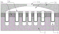
The suction and blowing part comprises a suction and blowing box body 31, the suction and blowing box body 31 is of a rectangular structure, a cavity 32 is formed in the suction and blowing box body 31, an upper air port 33 communicated with the cavity 32 is formed in the top of the suction and blowing box body 31, a plurality of lower air ports 34 communicated with the cavity 32 are formed in the bottom of the suction and blowing box body 31, the inner diameter of each lower air port 34 is smaller than that of the corresponding cavity 5, the lower air ports 34 are in one-to-one correspondence with the corresponding cavities 5, and the negative pressure fan is connected with the corresponding upper air ports 33 through an air pipe.
The clamping part comprises a clamping block 36, a plurality of through holes 35 which are in one-to-one correspondence with the cavities 5 are arranged on the clamping block 36, the size of each through hole 35 is not smaller than that of each cavity 5, and the size of each through hole 35 of the clamping part is gradually decreased from bottom to top.
The clamping blocks 36 comprise a first half clamping block 36 and a second half clamping block 36, the first half clamping block 36 is fixed at the bottom of the suction and blowing box body 31, the second clamping block 36 is arranged at the bottom of the suction and blowing box body 31 in a sliding manner, the inner sides of the first half clamping block 36 and the second half clamping block 36 are respectively provided with a plurality of semicircular grooves, and then the semicircular grooves of the first half clamping block and the second half clamping block 36 form a through hole 35.
The side of the suction and blowing box 31 is also provided with a telescopic motor, the output end of the telescopic motor is connected with the second half clamping block 36, and the second half clamping block 36 is driven by the telescopic motor to be close to or far away from the first half clamping block 36.
The material taking mechanism 3 is arranged at one side above the lower die holder, the bottom end of the clamping part is slightly higher than the top end of the lower die holder, the material taking mechanism 3 is connected with the output end of a linear motor, and the material taking mechanism 3 is driven by the linear motor to move in the horizontal direction.
The working principle of the patent is as follows:
the upper die holder and the lower die holder are assembled, raw materials are injected into the main heat flow channel 11, the raw materials enter and fill the whole product forming cavity through the pouring gate through the heating heat-preserving self-supporting heat flow channel 12 of the electric heating wire, products 6 in the product forming cavity after cooling are formed, then the upper die holder and the lower die holder are demolded, then the linear motor is started to drive the material taking mechanism 3 to move to the vertical upper part of the lower die holder, the products 6 on the lower die holder are adsorbed into the through holes 35 of the clamping part by utilizing the negative pressure fan, then the material taking mechanism 3 is moved to be far away from the lower die holder, the products 6 in the through holes 35 of the clamping part are blown down by utilizing the negative pressure fan, the manual material taking is not needed, the labor intensity is reduced, all the formed products 6 on the lower die holder can be taken out at one time, the taking efficiency is high, and scalding of workers cannot occur.
It will be understood by those skilled in the art that the present utility model is not limited to the embodiments described above, and that the above embodiments and descriptions are merely illustrative of the principles of the present utility model, and various changes and modifications may be made without departing from the spirit and scope of the utility model, which is defined in the appended claims. The scope of the utility model is defined by the appended claims and equivalents thereof.
Claims (6)
1. Hot runner mold convenient to ejection of compact, its characterized in that: comprising
The upper die holder is provided with an upper accommodating cavity at the bottom for installing an upper die core, a plurality of cores are installed at the bottom of the upper die core, and the distance between two adjacent cores is gradually increased from the middle part of the upper die core to the peripheral part of the upper die core;
the upper part of the lower die holder is provided with an upper accommodating cavity for installing a lower die core, the top of the lower die core is provided with a die cavity corresponding to the die core, and the upper die holder and the lower die holder are matched with each other, so that a product forming die cavity is formed between the die cavity and the die core;
the material taking mechanism is movably arranged and comprises a clamping part and a suction and blowing part, the suction and blowing part is arranged at the top of the clamping part and comprises a suction and blowing box body, a cavity is arranged in the suction and blowing box body, an upper air port communicated with the cavity is formed in the top of the suction and blowing box body, a plurality of lower air ports communicated with the cavity are formed in the bottom of the suction and blowing box body, the size of the lower air ports is smaller than that of the cavity, the lower air ports are in one-to-one correspondence with the cavity, the clamping part comprises a clamping block, a plurality of through holes in one-to-one correspondence with the cavity are formed in the clamping block, and the size of the through holes is not smaller than that of the cavity.
2. A hot runner mold for facilitating ejection of materials as defined in claim 1, wherein: the material taking mechanism is arranged at one side above the lower die holder, the bottom end of the clamping part is slightly higher than the top end of the lower die holder, the material taking mechanism is connected with the output end of a linear motor, and the material taking mechanism is driven to move in the horizontal direction by the linear motor.
3. A hot runner mold for facilitating ejection of materials as defined in claim 1, wherein: the material taking mechanism further comprises a negative pressure fan, and the negative pressure fan is connected with the upper air port through an air pipe.
4. A hot runner mold for facilitating ejection of materials as defined in claim 1, wherein: the mold is characterized in that a main heat flow channel is further formed in the upper mold core, a gate is arranged in the middle of one side of the mold core, a branch heat flow channel which is communicated with the main heat flow channel and the gate is arranged between the mold core and the upper mold core, and electric heating wires are arranged at the periphery of the main heat flow channel and the periphery of the branch heat flow channel.
5. A hot runner mold for facilitating ejection of materials as defined in claim 1, wherein: the size of the through hole of the clamping part is decreased from bottom to top.
6. A hot runner mold for facilitating ejection of materials as defined in claim 1, wherein: the clamping blocks comprise a first half clamping block and a second half clamping block, the first half clamping block is fixed at the bottom of the suction and blowing box body, the second clamping block is arranged at the bottom of the suction and blowing box body in a sliding mode, a plurality of semicircular grooves are formed in the inner sides of the first half clamping block and the second half clamping block, and then the semicircular grooves of the first half clamping block and the second half clamping block form the through hole.
Priority Applications (1)
| Application Number | Priority Date | Filing Date | Title |
|---|---|---|---|
| CN202223154861.4U CN219133080U (en) | 2022-11-28 | 2022-11-28 | Hot runner mold convenient for discharging |
Applications Claiming Priority (1)
| Application Number | Priority Date | Filing Date | Title |
|---|---|---|---|
| CN202223154861.4U CN219133080U (en) | 2022-11-28 | 2022-11-28 | Hot runner mold convenient for discharging |
Publications (1)
| Publication Number | Publication Date |
|---|---|
| CN219133080U true CN219133080U (en) | 2023-06-06 |
Family
ID=86592198
Family Applications (1)
| Application Number | Title | Priority Date | Filing Date |
|---|---|---|---|
| CN202223154861.4U Active CN219133080U (en) | 2022-11-28 | 2022-11-28 | Hot runner mold convenient for discharging |
Country Status (1)
| Country | Link |
|---|---|
| CN (1) | CN219133080U (en) |
-
2022
- 2022-11-28 CN CN202223154861.4U patent/CN219133080U/en active Active
Similar Documents
| Publication | Publication Date | Title |
|---|---|---|
| CN211074518U (en) | Injection mold is used in injection molding production | |
| CN203726729U (en) | Injection mold | |
| CN113772925A (en) | Compression molding device for glass insulator | |
| CN211307207U (en) | Injection mold with multi-channel structure | |
| CN219133080U (en) | Hot runner mold convenient for discharging | |
| CN202114867U (en) | Injection mold with insert | |
| CN207789639U (en) | A kind of effective injection mold of coiling | |
| CN213947227U (en) | Injection mold of plastic prefabricated part | |
| CN209176057U (en) | A kind of injection mold of automobile instrument dial | |
| CN115674602A (en) | Injection molding process of hot runner mold | |
| CN220242277U (en) | Mould for forming precise plastic gear | |
| CN213166596U (en) | Kettle body injection mold | |
| CN216001309U (en) | Mould with pneumatic type ejection mechanism | |
| CN220681493U (en) | Electric hub sleeve forming device | |
| CN219988319U (en) | Front shell forming die of air purifier | |
| CN220499861U (en) | Demoulding structure for injection molding | |
| CN214773597U (en) | Mould with high processing speed | |
| CN218462881U (en) | Quick demoulding device for cooling forming die | |
| CN210308840U (en) | Automatic demoulding injection mold | |
| CN219445998U (en) | Efficient forming die of die sinking | |
| CN219820404U (en) | Annular die for forming thermosetting composite material | |
| CN211467375U (en) | Injection mold capable of being cooled rapidly | |
| CN211165073U (en) | Injection mold for manufacturing generator blade | |
| CN215283136U (en) | Plastic box mould and ejection mechanism of mould | |
| CN115256825B (en) | Cooling injection mold |
Legal Events
| Date | Code | Title | Description |
|---|---|---|---|
| GR01 | Patent grant | ||
| GR01 | Patent grant |