CN219132675U - Building spandrel post pouring die - Google Patents
Building spandrel post pouring die Download PDFInfo
- Publication number
- CN219132675U CN219132675U CN202320265426.4U CN202320265426U CN219132675U CN 219132675 U CN219132675 U CN 219132675U CN 202320265426 U CN202320265426 U CN 202320265426U CN 219132675 U CN219132675 U CN 219132675U
- Authority
- CN
- China
- Prior art keywords
- bearing column
- fixedly connected
- driving
- building
- blocks
- Prior art date
- Legal status (The legal status is an assumption and is not a legal conclusion. Google has not performed a legal analysis and makes no representation as to the accuracy of the status listed.)
- Active
Links
Images


Abstract
The utility model belongs to the technical field of building pouring molds and relates to a building bearing column pouring mold, which comprises a bottom plate and a supporting plate, wherein a limiting frame is arranged on the left side of the supporting plate, two clamping blocks are arranged on one side, far away from the supporting plate, of the limiting frame in a sliding manner, bearing column molds are respectively arranged on the two clamping blocks, a fastening mechanism is arranged between the two bearing column molds, and a driving mechanism for driving the two clamping blocks to move is arranged in the limiting frame. The utility model has simple structure, the driving mechanism is arranged to drive the two clamping blocks to slide on the outer surface of the limiting frame, so that the two bearing column moulds are driven to be close to each other, the two bearing column moulds are attached together and clamped and fixed, and then the two bearing column moulds are further connected and fixed through the fastening mechanism, so that the bearing column moulds are always kept in a tightly connected state in the pouring process, thereby improving the pouring quality of the bearing column, and being simple and convenient to assemble and operate.
Description
Technical Field
The utility model belongs to the technical field of building pouring molds, and particularly relates to a building bearing column pouring mold.
Background
The bearing column is the main stress body of a building, the bearing column can bear pressure, the volume and the height of the building are determined, the bearing column is of a reinforced concrete structure, and a pouring die is often used in the pouring process of the bearing column.
The existing pouring mould for the building bearing column is often formed by combining two moulds together, and then the two moulds are fixed together, so that gaps are easily formed between the two moulds due to the influence of flowing concrete in the pouring process, and the concrete flows out, so that the quality of the poured bearing column can be influenced. CN202122293279.5 discloses a pouring mould for building spandrel post, including the base and set up in the shaping subassembly of base top, two sets of locating shafts have set firmly at the top of base, shaping subassembly is passed by two sets of locating shafts, and shaping subassembly rotationally installs in the top front side of base, drive adjustment subassembly has been installed to the top rear side of base. The pouring die for the building bearing column solves the problem that the existing pouring die for the building bearing column is poor in attaching and fixing tightness, but is complex in structure and troublesome to assemble and use.
Disclosure of Invention
Aiming at the defects of the prior art, the utility model provides a building bearing column pouring die, which solves the problems that the existing pouring die is complex in structure, troublesome to assemble and use, and easy to cause gaps between dies when pouring is influenced by flowing concrete, so that the concrete flows out, and the quality of the poured bearing column is influenced.
In order to achieve the above purpose, the utility model is realized by the following technical scheme:
the utility model provides a building spandrel post pouring die, includes bottom plate and fixed connection at the backup pad on bottom plate top, the spacing frame of the vertical setting of left side fixedly connected with of backup pad, spacing frame is kept away from one side surface sliding connection of backup pad has two sets of sliders, two sets of equal fixedly connected with grip block in one side of slider, two respectively fixedly connected with spandrel post mould between the opposite side of grip block, two be equipped with fastening mechanism between the spandrel post mould, be equipped with in the spacing frame and drive two actuating mechanism that the grip block removed.
Preferably, the driving mechanism comprises a connecting plate fixedly connected between the upper inner wall and the lower inner wall of the limiting frame, a driving shaft is rotatably connected between one side of the connecting plate and the opposite side of the supporting plate, one end of the driving shaft penetrates to the right side of the supporting plate and is fixedly connected with a driving motor through a coupling, the outer surface of the driving shaft is fixedly connected with a driving gear, two sides of the driving gear are respectively meshed with a transmission rack, and one end of each transmission rack is respectively fixedly connected with one side of each clamping block.
Preferably, the outer surfaces of the two transmission racks are both connected with limiting blocks in a sliding manner, and one sides of the two limiting blocks are both fixedly connected with one side of the connecting plate.
Preferably, a motor fixing frame is arranged between the bottom of the driving motor and the top surface of the bottom plate.
Preferably, the fastening mechanism comprises two threaded rods, two protruding blocks are fixedly connected to two sides of the bearing column die, each protruding block is provided with a threaded hole, and one end of each threaded rod penetrates through the two opposite protruding blocks and is in threaded connection with the nut.
Compared with the prior art, the utility model has the following beneficial effects:
this building spandrel post pouring die, including the bottom plate, spacing frame, the grip block, spandrel post mould and, fastening mechanism and actuating mechanism, its simple structure, through setting up actuating mechanism, when pouring the spandrel post, through starting driving motor, driving motor's output passes through the shaft coupling cooperation drive shaft and drives driving gear and rotate, it slides at the surface of spacing frame to drive the slider through driving gear cooperation two drive racks, make two grip blocks drive two spandrel post moulds be close to each other, laminating together and carry out the centre gripping fixed to it, then rethread threaded rod and nut cooperation protruding piece are further connected fixedly two spandrel post moulds, make spandrel post mould remain throughout under the inseparable state of connection in the in-process of pouring, thereby improve the quality of spandrel post of pouring, and its equipment and easy and simple to handle.
Drawings
FIG. 1 is a schematic diagram of the overall structure of the present utility model;
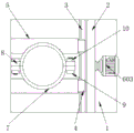
FIG. 2 is a schematic view of the casting state of the bearing post according to the present utility model;
FIG. 3 is a side view of the drive mechanism of the present utility model;
in the figure: 1. a bottom plate; 2. a support plate; 3. a limit frame; 4. a slide block; 5. a clamping block; 6. a driving mechanism; 601. a connecting plate; 602. a drive shaft; 603. a driving motor; 604. a drive gear; 605. a drive rack; 606. a limiting block; 7. a bearing column mould; 8. a protruding block; 9. a threaded rod; 10. and (3) a nut.
Detailed Description
The following description of the embodiments of the present utility model will be made clearly and completely with reference to the accompanying drawings, in which it is apparent that the embodiments described are only some embodiments of the present utility model, but not all embodiments. All other embodiments, which can be made by those skilled in the art based on the embodiments of the utility model without making any inventive effort, are intended to be within the scope of the utility model.
Referring to FIGS. 1-3, the present utility model provides two technical solutions
Example 1
The utility model provides a building spandrel post pouring die, including bottom plate 1 and fixed connection in backup pad 2 on bottom plate 1 top, the spacing frame 3 of the vertical setting of left side fixedly connected with of backup pad 2, one side surface sliding connection that the backup pad 2 was kept away from to spacing frame 3 has two sets of sliders 4, spacing frame 3 plays spacing effect to slider 4, the equal fixedly connected with grip block 5 in one side of two sets of sliders 4, equal fixedly connected with spandrel post mould 7 between the opposite side of two grip blocks 5, fix through fastening mechanism between two spandrel post moulds 7, fastening mechanism includes two threaded rods 9 and two nuts 10. Two sides of two spandrel post moulds 7 are all fixedly connected with protruding piece 8, and the screw hole has all been seted up to every protruding piece 8, threaded connection has threaded rod 9 and with threaded rod 9 matched with nut 10 between two relative protruding pieces 8, one side of nut 10 and one side contact of protruding piece 8, when two spandrel post moulds 7 are under the drive of actuating mechanism 6 when laminating, can carry out further connection fixed to two spandrel post moulds 7 through threaded rod 9 and nut 10's cooperation.
A driving mechanism 6 is arranged in the limit frame 3, and the driving mechanism 6 is used for driving the two clamping blocks 5 to move. The driving mechanism 6 comprises a connecting plate 601 fixedly connected between the upper inner wall and the lower inner wall of the limiting frame 3, a driving shaft 602 is rotationally connected between one side of the connecting plate 601 and the opposite side of the supporting plate 2, the connecting plate 601 plays a role in limiting and supporting the driving shaft 602, one end of the driving shaft 602 penetrates through the right side of the supporting plate 2 and is fixedly connected with a driving motor 603 through a coupling, a motor fixing frame is arranged between the bottom of the driving motor 603 and the top surface of the bottom plate 1, the motor fixing frame can increase the stability of the driving motor, the driving motor 603 is a three-phase asynchronous motor, the driving shaft 602 can be driven to rotate positively and negatively, and the driving motor is electrically connected with an external power supply through a corresponding control switch.
The outer surface of the driving shaft 602 is fixedly connected with a driving gear 604, and the driving motor 603 is started, and the output end of the driving motor 603 drives the driving shaft 602 to rotate through a coupler, so that the driving shaft 602 drives the driving gear 604 to rotate in the rotating process.
The two sides of the outer surface of the driving gear 604 are respectively meshed with the driving racks 605, the two driving racks 605 are respectively positioned on the two sides of the driving gear 604, teeth are respectively meshed with the teeth of the driving gear 604, one ends of the two driving racks 605 are respectively fixedly connected with one sides of the two clamping blocks 5, the outer surfaces of the two driving racks 605 are respectively and slidably connected with the limiting blocks 606, the limiting blocks 606 play a limiting role on the driving racks 605, one sides of the two limiting blocks 606 are fixedly connected with one side of the connecting plate 601, when the driving gear 604 rotates under the driving of the driving shaft 602, the teeth are meshed with the teeth of the two driving racks 605, so that the two clamping blocks 5 are driven to slide on the outer surface of the limiting frame 3 under the cooperation of the sliding blocks 4, so that the two clamping blocks 5 are close to each other, and simultaneously, the bearing column die 7 is clamped and fixed.
Example 2
The utility model provides a building spandrel post pouring die, include be equipped with the actuating mechanism 6 that drives two grip blocks 5 and remove between the inner wall of spacing frame 3, actuating mechanism 6 includes fixed connection at spacing frame 3 upper and lower two connecting plates 601 between the inner wall, rotate between one side of connecting plate 601 and the opposite side of backup pad 2 and be connected with drive shaft 602, connecting plate 601 plays spacing supporting role to drive shaft 602, the one end of drive shaft 602 runs through to the right side of backup pad 2, and through shaft coupling fixedly connected with driving motor 603, driving motor 603 is three-phase asynchronous motor, can drive shaft 602 and carry out positive and negative rotation, and through corresponding control switch and external power source electric connection.
The outer surface of the driving shaft 602 is fixedly connected with a driving gear 604, and the driving motor 603 is started, and the output end of the driving motor 603 drives the driving shaft 602 to rotate through a coupler, so that the driving shaft 602 drives the driving gear 604 to rotate in the rotating process.
The two sides of the outer surface of the driving gear 604 are respectively meshed with the driving racks 605, the two driving racks 605 are respectively positioned on the two sides of the driving gear 604, teeth are respectively meshed with the teeth of the driving gear 604, one ends of the two driving racks 605 are respectively fixedly connected with one sides of the two clamping blocks 5, the outer surfaces of the two driving racks 605 are respectively and slidably connected with the limiting blocks 606, the limiting blocks 606 play a limiting role on the driving racks 605, one sides of the two limiting blocks 606 are fixedly connected with one side of the connecting plate 601, when the driving gear 604 rotates under the driving of the driving shaft 602, the teeth are meshed with the teeth of the two driving racks 605, so that the two clamping blocks 5 are driven to slide on the outer surface of the limiting frame 3 under the cooperation of the sliding blocks 4, so that the two clamping blocks 5 are close to each other, and simultaneously, the bearing column die 7 is clamped and fixed.
And all that is not described in detail in this specification is well known to those skilled in the art.
When the bearing column pouring machine works, firstly, the driving motor 603 is started, the output end of the driving motor 603 drives the driving shaft 602 to rotate through the coupler, so that the driving shaft 602 drives the driving gear 604 connected with the outer surface to rotate in the rotating process, teeth of the driving gear 604 are meshed with teeth of the two driving racks 605 in the rotating process, the two driving racks 605 are driven to slide on the inner surfaces of the two limiting blocks 606, the clamping blocks 5 connected with one ends are driven to move respectively while sliding, the two clamping blocks 5 slide on the outer surface of the limiting frame 3 through the sliding blocks 4, and are close to each other, the bearing column dies 7 connected with one sides are driven to move respectively while being close to each other, the two bearing column dies 7 are made to be close to each other, and the opposite sides are attached together, at the moment, the two bearing column dies 7 are driven by the driving mechanism 6 to be subjected to preliminary close attachment, and clamped and fixed, then the threaded rod 9 is driven to pass through the inner surface of one protruding block 8 to one side of the other protruding block 8, and the clamping blocks 5 are connected with the threaded rod through the nuts 10, so that the bearing column dies are further fixed in the bearing column dies, and the bearing column dies 7 are always connected with each other, and the bearing column die is kept in a close state.
It is noted that relational terms such as first and second, and the like are used solely to distinguish one entity or action from another entity or action without necessarily requiring or implying any actual such relationship or order between such entities or actions. Moreover, the terms "comprises," "comprising," or any other variation thereof, are intended to cover a non-exclusive inclusion, such that a process, method, article, or apparatus that comprises a list of elements does not include only those elements but may include other elements not expressly listed or inherent to such process, method, article, or apparatus.
Although embodiments of the present utility model have been shown and described, it will be understood by those skilled in the art that various changes, modifications, substitutions and alterations can be made therein without departing from the principles and spirit of the utility model, the scope of which is defined in the appended claims and their equivalents.
Claims (5)
1. Building spandrel post pouring die, including bottom plate and fixed connection at the backup pad on bottom plate top, its characterized in that: the utility model discloses a support plate, including support plate, spacing frame, two sets of sliders, two sets of the equal fixedly connected with grip blocks of one side of slider, two fixedly connected with spandrel post mould respectively between the opposite side of grip block, two be equipped with fastening mechanism between the spandrel post mould, be equipped with in the spacing frame and drive two the actuating mechanism that the grip block removed.
2. The building load-bearing column casting mold according to claim 1, wherein: the driving mechanism comprises a connecting plate fixedly connected between the upper inner wall and the lower inner wall of the limiting frame, a driving shaft is rotatably connected between one side of the connecting plate and the opposite side of the supporting plate, one end of the driving shaft penetrates through to the right side of the supporting plate and is fixedly connected with a driving motor through a coupling, the outer surface of the driving shaft is fixedly connected with a driving gear, two sides of the driving gear are respectively meshed with a transmission rack, and one end of each transmission rack is respectively fixedly connected with one side of each clamping block.
3. The building load-bearing column casting mold according to claim 2, wherein: the outer surfaces of the two transmission racks are both connected with limiting blocks in a sliding mode, and one sides of the two limiting blocks are both fixedly connected with one side of the connecting plate.
4. The building load-bearing column casting mold according to claim 2, wherein: and a motor fixing frame is arranged between the bottom of the driving motor and the top surface of the bottom plate.
5. The building load-bearing column casting mold according to claim 1, wherein: the fastening mechanism comprises two threaded rods, two protruding blocks are fixedly connected to two sides of the bearing column die, each protruding block is provided with a threaded hole, and one end of each threaded rod penetrates through the two opposite protruding blocks and is in threaded connection with a nut.
Priority Applications (1)
| Application Number | Priority Date | Filing Date | Title |
|---|---|---|---|
| CN202320265426.4U CN219132675U (en) | 2023-02-21 | 2023-02-21 | Building spandrel post pouring die |
Applications Claiming Priority (1)
| Application Number | Priority Date | Filing Date | Title |
|---|---|---|---|
| CN202320265426.4U CN219132675U (en) | 2023-02-21 | 2023-02-21 | Building spandrel post pouring die |
Publications (1)
| Publication Number | Publication Date |
|---|---|
| CN219132675U true CN219132675U (en) | 2023-06-06 |
Family
ID=86560450
Family Applications (1)
| Application Number | Title | Priority Date | Filing Date |
|---|---|---|---|
| CN202320265426.4U Active CN219132675U (en) | 2023-02-21 | 2023-02-21 | Building spandrel post pouring die |
Country Status (1)
| Country | Link |
|---|---|
| CN (1) | CN219132675U (en) |
-
2023
- 2023-02-21 CN CN202320265426.4U patent/CN219132675U/en active Active
Similar Documents
| Publication | Publication Date | Title |
|---|---|---|
| CN219132675U (en) | Building spandrel post pouring die | |
| CN218424448U (en) | Vertical boring and washing processing equipment for production of precision mold | |
| CN219665800U (en) | Engraving structure on aluminum profile surface | |
| CN213006159U (en) | Steel lining plastic pipe fitting forming equipment | |
| CN211221244U (en) | Precast concrete cement mould | |
| CN113664682A (en) | Mold inner cavity hole grinding machine and working method thereof | |
| CN214833779U (en) | Prefabricated component exterior wall panel mould of assembly type structure | |
| CN217451818U (en) | Forming die is used in electric motor car wheel hub processing | |
| CN216632532U (en) | Die casting die mold insert processing is with automatic locking tool | |
| CN216681669U (en) | Injection mold processing is with burnishing device that has multi-angle function of polishing | |
| CN211386595U (en) | Clamping fixture for automobile mold | |
| CN214161322U (en) | Sand mold template machine convenient for demolding | |
| CN218668549U (en) | Spiral aluminum mould supporting device | |
| CN219338369U (en) | Injection mold with scalding prevention mechanism at edge | |
| CN213411468U (en) | Be used for automobile parts processing grinding device | |
| CN220389217U (en) | Automobile part mold processing device convenient to fix | |
| CN219006416U (en) | Forming device for cement brick processing | |
| CN215355957U (en) | Spring processing die | |
| CN219381016U (en) | Automatic cantilever paddle demolding equipment | |
| CN217454321U (en) | Evaporate and press lightweight aerated concrete board preparation facilities | |
| CN219855630U (en) | Composite material part forming die | |
| CN216151742U (en) | Corrosion-resistant clamping die for production of vehicle parts | |
| CN220837820U (en) | Die structure for manufacturing power transmission and distribution shell | |
| CN219114372U (en) | Auxiliary shaping device for reinforcing steel bars inside concrete prefabricated part | |
| CN213164664U (en) | Surface polishing device for mold production |
Legal Events
| Date | Code | Title | Description |
|---|---|---|---|
| GR01 | Patent grant | ||
| GR01 | Patent grant |