CN219130836U - Three hole location drilling equipment of hydraulic prop top cap - Google Patents
Three hole location drilling equipment of hydraulic prop top cap Download PDFInfo
- Publication number
- CN219130836U CN219130836U CN202223428373.8U CN202223428373U CN219130836U CN 219130836 U CN219130836 U CN 219130836U CN 202223428373 U CN202223428373 U CN 202223428373U CN 219130836 U CN219130836 U CN 219130836U
- Authority
- CN
- China
- Prior art keywords
- wall
- hydraulic prop
- top cap
- top cover
- sleeve
- Prior art date
- Legal status (The legal status is an assumption and is not a legal conclusion. Google has not performed a legal analysis and makes no representation as to the accuracy of the status listed.)
- Active
Links
Images

Classifications
-
- Y—GENERAL TAGGING OF NEW TECHNOLOGICAL DEVELOPMENTS; GENERAL TAGGING OF CROSS-SECTIONAL TECHNOLOGIES SPANNING OVER SEVERAL SECTIONS OF THE IPC; TECHNICAL SUBJECTS COVERED BY FORMER USPC CROSS-REFERENCE ART COLLECTIONS [XRACs] AND DIGESTS
- Y02—TECHNOLOGIES OR APPLICATIONS FOR MITIGATION OR ADAPTATION AGAINST CLIMATE CHANGE
- Y02E—REDUCTION OF GREENHOUSE GAS [GHG] EMISSIONS, RELATED TO ENERGY GENERATION, TRANSMISSION OR DISTRIBUTION
- Y02E10/00—Energy generation through renewable energy sources
- Y02E10/20—Hydro energy
Landscapes
- Drilling And Boring (AREA)
Abstract
The utility model discloses a three-hole positioning and drilling device for a hydraulic prop top cover, which comprises a mounting seat, wherein mounting clamping pieces are arranged on the outer surfaces of two ends of the mounting seat. This three hole location drilling equipment of hydraulic prop top cap, top cap mount through setting up, the trompil, buffer spacer, the installation fastener, the mount, the top cap dead lever, fixation nut, the drill bit locating part, the mounting, the fixed pipe, rotate the handle, fixed sleeve, the spacing ring, rotate the sleeve, spacing jack, rotating piece and spacing inserted bar, when hydraulic prop top cap drilling, accessible fixation nut installs hydraulic prop top cap on the top cap mount, in inserting spacing jack again with spacing inserted bar card, adjust the angle of top cap mount, the drill bit can insert the drill bit locating part and carry out the trompil to hydraulic prop top cap outer wall, make things convenient for the processing personnel to fix the hydraulic prop top cap, can also improve the drilling efficiency of hydraulic prop top cap.
Description
Technical Field
The utility model relates to the field of positioning and drilling devices, in particular to a three-hole positioning and drilling device for a hydraulic prop top cover.
Background
A three-hole positioning and drilling device for a hydraulic prop top cover is a device for positioning and fixing the hydraulic prop top cover in the drilling process of the hydraulic prop top cover.
The existing three-hole positioning drilling device for the hydraulic prop top cover has certain defects when in use, firstly, the fixing effect of the hydraulic prop top cover is poor, and secondly, the drilling efficiency of the device is low.
Therefore, it is necessary to provide a three-hole positioning and drilling device for a hydraulic prop top cover to solve the above problems.
Disclosure of Invention
The utility model mainly aims to provide a three-hole positioning drilling device for a hydraulic prop top cover, which can effectively solve the problems in the background technology.
In order to achieve the above purpose, the technical scheme adopted by the utility model is as follows:
the utility model provides a three hole location drilling equipment of hydraulic prop top cap, includes the mount pad, the both ends surface of mount pad all is provided with the installation fastener, the upper end middle part of mount pad is provided with the mount, the upper end surface of mount is provided with fixed sleeve, fixed sleeve's upper end one side is provided with the fixed pipe, the inner wall of fixed pipe is provided with the rotating block, one side surface of rotating block is provided with rotates the handle, the lower extreme middle part of rotating block is provided with spacing inserted bar, fixed sleeve's upper end opposite side is provided with the mounting, the upper end surface of mounting is provided with the drill bit locating part, fixed sleeve's inner wall is provided with the rotation sleeve, spacing jack has been seted up to rotation sleeve's one side surface, one side surface of limit ring is provided with the top cap mount, the outer wall of limit ring is provided with the cushion pad, one side surface of top cap mount is provided with the top cap dead lever, the outer wall of top cap dead lever is provided with fixation nut.
Preferably, both ends surface of mount pad all can dismantle with the outer wall of installation fastener and be connected, the upper end middle part of mount pad and the lower extreme surface fixed connection of mount, the upper end surface of mount and the lower extreme surface fixed connection of fixed sleeve, the upper end one side of fixed sleeve and the lower extreme surface fixed connection of fixed pipe, the inner wall of fixed pipe and the outer wall swing joint of rotating block, one side surface and the one end surface fixed connection of rotating handle of rotating block, the lower extreme middle part and the upper end surface fixed connection of spacing inserted bar of rotating block, the upper end opposite side of fixed sleeve and the lower extreme surface fixed connection of mounting, the upper end surface of mounting and the lower extreme surface fixed connection of drill bit locating part, the inner wall of fixed sleeve and the outer wall swing joint of rotating sleeve, the outer wall of spacing inserted bar can be dismantled with the inner wall of spacing jack and be connected, one side surface fixed connection of one side surface of spacing ring and the one side surface fixed connection of the top cap of mount, the outer wall of spacing ring and one side of buffer spacer and the outer surface fixed connection of top cap, the outer wall fixed connection of top cap and the top cap of one side of the fixed nut is favorable to dismantle the whole fixed device of the fixed nut.
Compared with the prior art, the utility model provides the three-hole positioning drilling device for the hydraulic prop top cover, which has the following beneficial effects:
this three hole location drilling equipment of hydraulic prop top cap, top cap mount through setting up, the trompil, buffer spacer, the installation fastener, the mount, the top cap dead lever, fixation nut, the drill bit locating part, the mounting, the fixed pipe, rotate the handle, fixed sleeve, the spacing ring, rotate the sleeve, spacing jack, rotating piece and spacing inserted bar, when hydraulic prop top cap drilling, accessible fixation nut installs hydraulic prop top cap on the top cap mount, in inserting spacing jack again with spacing inserted bar card, adjust the angle of top cap mount, the drill bit can insert the drill bit locating part and carry out the trompil to hydraulic prop top cap outer wall, make things convenient for the processing personnel to fix the hydraulic prop top cap, can also improve the drilling efficiency of hydraulic prop top cap.
Drawings
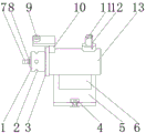
Fig. 1 is a schematic diagram of the overall structure of the present utility model.
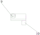
Fig. 2 is a schematic diagram of a partial structure of the present utility model.
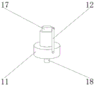
Fig. 3 is a schematic diagram of a partial structure of the present utility model.
Fig. 4 is a schematic diagram of a partial structure of the present utility model.
In the figure: 1. a top cover fixing frame; 2. opening holes; 3. a buffer pad; 4. installing a clamping piece; 5. a mounting base; 6. a fixing frame; 7. a top cover fixing rod; 8. a fixing nut; 9. a drill bit limiter; 10. a fixing member; 11. a fixed tube; 12. rotating the handle; 13. a fixed sleeve; 14. a limiting ring; 15. rotating the sleeve; 16. limiting jack; 17. a rotating block; 18. and a limiting inserted link.
Detailed Description
The utility model is further described in connection with the following detailed description, in order to make the technical means, the creation characteristics, the achievement of the purpose and the effect of the utility model easy to understand.
As shown in fig. 1-4, a three-hole positioning drilling device for a hydraulic prop top cover comprises a mounting seat 5, wherein mounting clamping pieces 4 are arranged on the outer surfaces of two ends of the mounting seat 5, a fixing frame 6 is arranged in the middle of the upper end of the mounting seat 5, a fixing sleeve 13 is arranged on the outer surface of the upper end of the fixing frame 6, a fixing pipe 11 is arranged on one side of the upper end of the fixing sleeve 13, a rotating block 17 is arranged on the inner wall of the fixing pipe 11, a rotating grip 12 is arranged on the outer surface of one side of the rotating block 17, a limiting inserting rod 18 is arranged in the middle of the lower end of the rotating block 17, a fixing piece 10 is arranged on the other side of the upper end of the fixing sleeve 13, a drill bit limiting piece 9 is arranged on the outer surface of the upper end of the fixing piece 10, a rotating sleeve 15 is arranged on the inner wall of the fixing sleeve 13, a limiting inserting hole 16 is formed in the outer wall of the rotating sleeve 15, a limiting ring 14 is arranged on the outer surface of one side of the rotating sleeve 15, and the top cover 1 is arranged on one side of the limiting ring 14, the outer wall of the limiting ring 14 is provided with a buffer gasket 3, the outer wall of the top cover fixing frame 1 is provided with an opening 2, one side outer surface of the top cover fixing frame 1 is provided with a top cover fixing rod 7, the outer wall of the top cover fixing rod 7 is provided with a fixing nut 8, the outer surfaces of the two ends of the mounting seat 5 are detachably connected with the outer wall of the mounting clamping piece 4, the middle part of the upper end of the mounting seat 5 is fixedly connected with the outer surface of the lower end of the fixing frame 6, the outer surface of the upper end of the fixing frame 6 is fixedly connected with the outer surface of the lower end of the fixing sleeve 13, one side of the upper end of the fixing sleeve 13 is fixedly connected with the outer surface of the lower end of the fixing pipe 11, the inner wall of the fixing pipe 11 is movably connected with the outer wall of the rotating block 17, one side outer surface of the rotating block 17 is fixedly connected with one end outer surface of the rotating handle 12, the middle part of the lower end of the rotating block 17 is fixedly connected with the outer surface of the upper end of the limiting inserting rod 18, the upper end opposite side of fixed sleeve 13 and the lower extreme surface fixed connection of mounting 10, the upper end surface of mounting 10 and the lower extreme surface fixed connection of drill bit locating part 9, the inner wall of fixed sleeve 13 and the outer wall swing joint of rotating sleeve 15, the outer wall of spacing inserted bar 18 and the inner wall of spacing jack 16 are dismantled and are connected, one side surface of rotating sleeve 15 and one side surface fixed connection of spacing ring 14, the opposite side surface of spacing ring 14 and one side surface fixed connection of top cap mount 1, the outer wall of spacing ring 14 and one side surface fixed connection of buffer pad 3, the opposite side surface of top cap mount 1 and one side surface fixed connection of top cap dead lever 7, the outer wall of top cap dead lever 7 and the outer wall of fixation nut 8 can be dismantled and be connected, be favorable to locating drilling equipment's overall structure stability.
Principle of operation
The utility model relates to a three-hole positioning and drilling device for a hydraulic prop top cover, which is characterized in that when in use, an installation seat 5 is installed on drilling equipment through an installation clamping piece 4, then the hydraulic prop top cover is fixed on a top cover fixing frame 1 through a fixing nut 8, a drill bit is inserted into a drill bit limiting piece 9 to open a hole on the outer wall of the hydraulic prop top cover, and the arranged top cover fixing frame, the open hole, a buffer gasket, the installation clamping piece, the installation seat, the fixing frame, a top cover fixing rod, a fixing nut, the drill bit limiting piece, a fixing pipe, a rotating handle, a fixing sleeve, a limiting ring, a rotating sleeve, a limiting jack, a rotating block and a limiting inserted rod are arranged on the three-hole positioning and drilling device, so that a processor can conveniently fix the hydraulic prop top cover and can also improve the drilling efficiency of the hydraulic prop top cover.
The foregoing has shown and described the basic principles and main features of the present utility model and the advantages of the present utility model. It will be understood by those skilled in the art that the present utility model is not limited to the embodiments described above, and that the above embodiments and descriptions are merely illustrative of the principles of the present utility model, and various changes and modifications may be made without departing from the spirit and scope of the utility model, which is defined in the appended claims. The scope of the utility model is defined by the appended claims and equivalents thereof.
Claims (6)
1. Three hole location drilling equipment of hydraulic prop top cap, including mount pad (5), its characterized in that: the utility model discloses a top cover, including mount pad (5) and top cover, mount pad (5) are provided with mounting fastener (4) on both ends surface, the upper end middle part of mount pad (5) is provided with mount (6), the upper end surface of mount (6) is provided with fixed sleeve (13), the upper end one side of fixed sleeve (13) is provided with fixed pipe (11), the inner wall of fixed pipe (11) is provided with rotating block (17), one side surface of rotating block (17) is provided with rotation handle (12), the lower extreme middle part of rotating block (17) is provided with spacing inserted bar (18), the upper end opposite side of fixed sleeve (13) is provided with mounting (10), the upper end surface of mounting (10) is provided with drill bit locating part (9), the inner wall of fixed sleeve (13) is provided with rotating sleeve (15), limiting jack (16) have been seted up to the outer wall of rotating sleeve (15), one side surface of rotating sleeve (15) is provided with spacing ring (14), one side surface of spacing ring (14) is provided with top cover (1), top cover (1) is provided with top cover (1) outer wall (3), top cover (1) is provided with top cover (1), the outer wall of the top cover fixing rod (7) is provided with a fixing nut (8).
2. The hydraulic prop roof three-hole positioning drilling device according to claim 1, wherein: the outer surfaces of the two ends of the mounting seat (5) are detachably connected with the outer wall of the mounting clamping piece (4), the middle part of the upper end of the mounting seat (5) is fixedly connected with the outer surface of the lower end of the fixing frame (6), and the outer surface of the upper end of the fixing frame (6) is fixedly connected with the outer surface of the lower end of the fixing sleeve (13).
3. The hydraulic prop roof three-hole positioning drilling device according to claim 1, wherein: the upper end one side of fixed sleeve (13) is fixedly connected with the lower extreme surface of fixed pipe (11), the inner wall of fixed pipe (11) and the outer wall swing joint of turning block (17), one side surface of turning block (17) and the one end surface fixed connection of turning handle (12), the lower extreme middle part of turning block (17) and the upper end surface fixed connection of spacing inserted bar (18).
4. The hydraulic prop roof three-hole positioning drilling device according to claim 1, wherein: the upper end opposite side of fixed sleeve (13) and the lower extreme surface fixed connection of mounting (10), the upper end surface of mounting (10) and the lower extreme surface fixed connection of drill bit locating part (9), the inner wall of fixed sleeve (13) and the outer wall swing joint of rotating sleeve (15), the outer wall of spacing inserted bar (18) and the inner wall detachable connection of spacing jack (16).
5. The hydraulic prop roof three-hole positioning drilling device according to claim 1, wherein: one side outer surface of the rotating sleeve (15) is fixedly connected with one side outer surface of the limiting ring (14), the other side outer surface of the limiting ring (14) is fixedly connected with one side outer surface of the top cover fixing frame (1), and the outer wall of the limiting ring (14) is fixedly connected with one side outer surface of the buffer gasket (3).
6. The hydraulic prop roof three-hole positioning drilling device according to claim 1, wherein: the outer surface of the other side of the top cover fixing frame (1) is fixedly connected with the outer surface of one side of the top cover fixing rod (7), and the outer wall of the top cover fixing rod (7) is detachably connected with the outer wall of the fixing nut (8).
Priority Applications (1)
| Application Number | Priority Date | Filing Date | Title |
|---|---|---|---|
| CN202223428373.8U CN219130836U (en) | 2022-12-21 | 2022-12-21 | Three hole location drilling equipment of hydraulic prop top cap |
Applications Claiming Priority (1)
| Application Number | Priority Date | Filing Date | Title |
|---|---|---|---|
| CN202223428373.8U CN219130836U (en) | 2022-12-21 | 2022-12-21 | Three hole location drilling equipment of hydraulic prop top cap |
Publications (1)
| Publication Number | Publication Date |
|---|---|
| CN219130836U true CN219130836U (en) | 2023-06-06 |
Family
ID=86559984
Family Applications (1)
| Application Number | Title | Priority Date | Filing Date |
|---|---|---|---|
| CN202223428373.8U Active CN219130836U (en) | 2022-12-21 | 2022-12-21 | Three hole location drilling equipment of hydraulic prop top cap |
Country Status (1)
| Country | Link |
|---|---|
| CN (1) | CN219130836U (en) |
-
2022
- 2022-12-21 CN CN202223428373.8U patent/CN219130836U/en active Active
Similar Documents
| Publication | Publication Date | Title |
|---|---|---|
| CN219604426U (en) | Building engineering foundation pile detects fixer | |
| CN219130836U (en) | Three hole location drilling equipment of hydraulic prop top cap | |
| CN210517686U (en) | Anti-seismic support hanger for cable bridge | |
| CN210240841U (en) | Interface sealing structure of nodular cast iron pipe | |
| CN219315727U (en) | Pile body fixing device for foundation pile construction | |
| CN212406605U (en) | Drilling device for geotechnical engineering | |
| CN212563235U (en) | Shaft heading machine | |
| CN208584671U (en) | A kind of ceramic tile hole making drill | |
| CN220320487U (en) | Natural gas transmission station pipeline safety device | |
| CN205918380U (en) | To one side straight dual -purpose rat hole pipe | |
| CN213755629U (en) | Digging device based on forestry machinery | |
| CN219528646U (en) | Protection plate for constructional engineering | |
| CN220378459U (en) | Adjustable supporting device for hydraulic end of fracturing pump | |
| CN210835916U (en) | Construction engineering monitoring server | |
| CN218152769U (en) | Metal pipe fitting for reinforcing installation | |
| CN220343057U (en) | Municipal afforestation engineering view fixer | |
| CN219412068U (en) | Corrosion-resistant steel tube tower of power transmission tower | |
| CN219912040U (en) | Pipeline pipe hoop for installing gas pipeline wall surface | |
| CN218581184U (en) | Anti-tilting device for supporting building template | |
| CN220692485U (en) | Slip ring fixing support of wind generating set | |
| CN216190580U (en) | Tower machine pull rod auxiliary installation device easy to assemble | |
| CN219015685U (en) | Portable shallow soil drilling sampling device | |
| CN215640234U (en) | Environmental engineering soil detection sampler | |
| CN220813554U (en) | Aluminum alloy vertical rod gasket for barrier gate and mounting structure thereof | |
| CN220747775U (en) | Detachable steel structure for construction site |
Legal Events
| Date | Code | Title | Description |
|---|---|---|---|
| GR01 | Patent grant | ||
| GR01 | Patent grant |