CN219130123U - Conveyer belt core surface cleaning mechanism - Google Patents
Conveyer belt core surface cleaning mechanism Download PDFInfo
- Publication number
- CN219130123U CN219130123U CN202320262000.3U CN202320262000U CN219130123U CN 219130123 U CN219130123 U CN 219130123U CN 202320262000 U CN202320262000 U CN 202320262000U CN 219130123 U CN219130123 U CN 219130123U
- Authority
- CN
- China
- Prior art keywords
- conveyer belt
- bracket
- conveyor belt
- core
- wiper blade
- Prior art date
- Legal status (The legal status is an assumption and is not a legal conclusion. Google has not performed a legal analysis and makes no representation as to the accuracy of the status listed.)
- Active
Links
Images
Abstract
The application discloses conveyer belt area core surface cleaning mechanism is applied to cleaning equipment technical field, including clean bench, conveyer belt and edge the direction of conveyer belt conveying sets gradually clean mechanism, wiper blade and drying-machine, the conveyer belt is used for conveying conveyer belt area core, the below of the both sides of clean bench is provided with the header tank symmetrically, clean mechanism includes the edge the water flushing pipe and the brush roller that the direction of delivery of conveyer belt set gradually, the water flushing pipe will the surface wetting of conveyer belt area core, the brush roller will the surface cleaning of conveyer belt area core, the wiper blade is scraped away most water stain on the surface of conveyer belt area core, the drying-machine will remain moisture on the conveyer belt area core weathers. The surface of the conveyer belt core is cleaned before the conveyer belt core is put into use, so that the problem that impurities are attached to the surface of the conveyer belt core in the production process is solved, and the quality of the conveyer belt core is improved.
Description
Technical Field
The utility model relates to the technical field of cleaning equipment, in particular to a belt core surface cleaning mechanism of a conveyor belt.
Background
The conveyor belt is widely applied to industries such as cement, coking, metallurgy, chemical industry, steel and the like, and is suitable for occasions with shorter conveying distance and smaller conveying amount.
In the prior art, the utility model patent with the application number of 202022498259.7 discloses a conveyor belt core, which comprises a framework layer and a covering glue layer, wherein the framework layer comprises a row of closely arranged braided ropes, the covering glue layer is wrapped around the braided ropes, the conveyor belt core is made by wrapping the covering glue layer around the row of closely arranged braided ropes, and the manufacturing process flow of the conveyor belt core comprises drying, plasticating, mixing, parking, heat-smelting, calendaring, forming, vulcanizing and packaging.
The production process steps of conveyer belt area core are numerous, probably have waste material, impurity attached to the surface of conveyer belt area core, influence the quality by the transportation product easily, from this, this application provides a conveyer belt area core surface cleaning mechanism, carries out surface cleaning to conveyer belt area core before conveyer belt area core goes into use.
Disclosure of Invention
The utility model provides a conveyor belt core surface cleaning mechanism which comprises a cleaning table, a conveyor belt, a cleaning mechanism, a wiper blade and a dryer, wherein the cleaning mechanism, the wiper blade and the dryer are sequentially arranged along the conveying direction of the conveyor belt, the conveyor belt is arranged on the cleaning table in a directional rotation mode and is used for conveying the conveyor belt core, water collecting tanks are symmetrically arranged below two sides of the cleaning table, the cleaning mechanism comprises a water flushing pipe and a brush roll, the water flushing pipe and the brush roll are sequentially arranged along the conveying direction of the conveyor belt, the water flushing pipe extends along the width direction of the cleaning table, the water flushing pipe, the brush roll and the wiper blade are all parallel to the cleaning table, water outlets are uniformly arranged on the water flushing pipe, the water outlets are opposite to the upper surface of the conveyor belt, gaps with preset sizes are kept between the bottom ends of the wiper blade and the conveyor belt, and air outlet holes of the dryer are opposite to the upper surface of the conveyor belt.
According to an embodiment of the utility model, the cleaning means are implemented in two groups, which are arranged in succession along the direction of conveyance of the conveyor belt.
According to an embodiment of the present utility model, a first bracket, a second bracket, a third bracket, a fourth bracket, a fifth bracket and a sixth bracket are disposed on two sides of the cleaning table, the first bracket is connected to the flushing pipe, the second bracket is connected to the brush roller, the third bracket is connected to the wiper blade, the fourth bracket is connected to the dryer, and the fifth bracket and the sixth bracket are respectively connected to the flushing pipe and the brush roller of the second group of the cleaning mechanism.
According to an embodiment of the utility model, the wiper blade is curved in a direction opposite to the direction of conveyance of the conveyor belt.
According to one embodiment of the utility model, a seventh bracket is arranged between the dryer and the brush roller on two sides of the cleaning table, and is connected with a water absorbing sponge, and the water absorbing sponge is matched with the surface of the belt core of the conveying belt.
According to an embodiment of the present utility model, the outside of the water absorbing sponge and the seventh supporting frame is covered with a wiping cloth.
According to an embodiment of the utility model, the flushing pipe is connected with a shower head at the water outlet.
The utility model has the beneficial effects that: the utility model relates to a conveyor belt core surface cleaning mechanism, which is provided with a cleaning table, wherein a conveyor belt is arranged on the cleaning table and is used for conveying a conveyor belt core, water collection tanks are arranged below two sides of the cleaning table and are used for receiving and cleaning water stains on the surface of the conveyor belt core, a flushing pipe, a brush roller, a wiper plate and a dryer are sequentially arranged along the conveying direction of the cleaning table, the flushing pipe just wets the surface of the conveyor belt core, the brush roller cleans the surface of the conveyor belt core, the wiper plate scrapes most of the water stains on the surface of the conveyor belt core, and the dryer dries the water remained on the conveyor belt core. The application provides a conveyer belt area core surface cleaning mechanism carries out surface cleaning to conveyer belt area core before conveyer belt area core put into use, has solved in the production process the surface of conveyer belt area core adheres to the problem of impurity, has improved the quality of conveyer belt area core.
These and other objects, features and advantages of the present utility model will become more fully apparent from the following detailed description.
Drawings
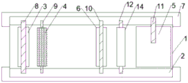
Fig. 1 shows a schematic top view of the present application.
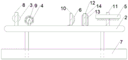
Fig. 2 shows a schematic diagram of the front view structure of the present application.
Reference numerals: 1-conveyer belt, 2-clean bench, 3-wash pipe, 4-brush roller, 5-drying-machine, 6-wiper blade, 7-header tank, 8-first support, 9-second support, 10-third support, 11-fourth support, 12-seventh support, 13-water absorbing sponge, 14-wiping cloth.
Detailed Description
The following description is presented to enable one of ordinary skill in the art to make and use the utility model. The preferred embodiments in the following description are by way of example only and other obvious variations will occur to those skilled in the art. The basic principles of the utility model defined in the following description may be applied to other embodiments, variations, modifications, equivalents, and other technical solutions without departing from the spirit and scope of the utility model.
It will be appreciated by those skilled in the art that in the disclosure of the present specification, the terms "longitudinal," "transverse," "upper," "lower," "front," "rear," "left," "right," "vertical," "horizontal," "top," "bottom," "inner," "outer," etc. refer to an orientation or positional relationship based on that shown in the drawings, which is merely for convenience of description and to simplify the description, and do not indicate or imply that the apparatus or elements referred to must have a particular orientation, be constructed and operated in a particular orientation, and therefore, the above terms should not be construed as limiting the present utility model.
It will be understood that the terms "a" and "an" should be interpreted as referring to "at least one" or "one or more," i.e., in one embodiment, the number of elements may be one, while in another embodiment, the number of elements may be plural, and the term "a" should not be interpreted as limiting the number.
Referring to fig. 1 and 2, a conveyor belt core surface cleaning mechanism according to a preferred embodiment of the present utility model will be described in detail below, wherein the conveyor belt core surface cleaning mechanism includes a cleaning table 2, a conveyor belt 1, and a cleaning mechanism, a wiper blade 6 and a dryer 5 sequentially disposed in a conveying direction of the conveyor belt 1, the conveyor belt 1 is disposed on the cleaning table 2 in a manner capable of directional rotation for conveying the conveyor belt core, water collection tanks 7 are symmetrically disposed under both sides of the cleaning table 2, the cleaning mechanism includes a flushing pipe 3 and a brush roller 4 sequentially disposed in a conveying direction of the conveyor belt 1, the flushing pipe 3 extends in a width direction of the cleaning table 2, the flushing pipe 3, the brush roller 4 and the wiper blade 6 are all parallel to the cleaning table 2, the flushing pipe 3 is uniformly provided with water outlets facing an upper surface of the conveyor belt 1, a gap between a bottom end of the wiper blade 6 and the conveyor belt 1 is maintained facing a predetermined small gap on the dryer surface 5. The cleaning device is characterized in that the conveyor belt core is placed on a conveyor belt 1 of a cleaning table 2 after being produced and molded, the conveyor belt 1 conveys the conveyor belt core, the conveyor belt 1 drives the conveyor belt core to move along the conveying direction of the conveyor belt 1, the conveyor belt core passes through a flushing pipe 3, a brush roll 4, a wiper blade 6 and a dryer 5 successively, the surface of the conveyor belt core is wetted by water flow of the flushing pipe 3, so that the brush roll 4 cleans the conveyor belt core, and the brush roll 4 is matched with the conveyor belt core to remove impurities on the surface of the conveyor belt core. The water collection tank 7 is symmetrically arranged below the cleaning table 2, and water stains generated by flushing the surface of the belt core of the conveyor belt flow into the water collection tank 7. After the conveyer belt core is cleaned by the cleaning mechanism, most of water stains on the surface of the conveyer belt core are scraped into the water collection tank 7 by the wiper blade 6, and the air outlet hole of the dryer 5 is opposite to the conveyer belt core, so that the surface of the conveyer belt core is quickly dried.
Preferably, the cleaning mechanisms are implemented in two groups, two groups of the cleaning mechanisms are sequentially arranged along the conveying direction of the conveying belt 1, the first group of cleaning mechanisms cleans most of dirt on the surface of the belt core of the conveying belt, and the second group of cleaning mechanisms cleans again, so that the cleaning effect is better.
Preferably, a first bracket 8, a second bracket 9, a third bracket 10, a fourth bracket 11, a fifth bracket and a sixth bracket are arranged on two sides of the cleaning table 2, the first bracket 8 is connected with the flushing pipe 3 and is used for supporting the flushing pipe 3, so that the flushing pipe 3 is arranged on the upper surface of the belt core of the conveyor belt; the second bracket 9 is connected with the brush roll 4 and is used for supporting the brush roll 4 so that the brush roll 4 just contacts the surface of the belt core of the conveyor belt; the third bracket 10 is connected to the wiper blade 6, and is used for supporting the wiper blade 6, so that a preset distance is reserved between the wiper blade 6 and the surface of the belt core of the conveyor belt, thereby ensuring that the wiper blade 6 can scrape off water stains on the belt core of the conveyor belt, and simultaneously avoiding the wiper blade 6 from wearing the belt core of the conveyor belt; the fourth bracket 11 is connected to the dryer 5 and is used for supporting the dryer 5. The fifth and sixth brackets are respectively connected to the water flushing pipe and the brush roller of the second cleaning mechanism (the second cleaning mechanism is arranged between the first cleaning mechanism and the dryer, and is not shown).
Preferably, the wiper blade 6 is curved, and the direction in which the wiper blade 6 is curved is opposite to the direction in which the conveyor belt 1 is conveyed, thereby functioning as a guide.
Preferably, a seventh support 12 is disposed between the dryer 5 and the brush roller 4 on two sides of the cleaning table 2, the seventh support 12 is connected with a water absorbing sponge 13, the water absorbing sponge 13 is matched with the surface of the belt core of the conveyor belt, and after the water stains on the surface of the belt core of the conveyor belt are scraped by the wiper blade 6, the surface of the belt core of the conveyor belt is in a wet state, so that the belt core of the conveyor belt is dried by the dryer 5 for accelerating, and the water absorbing sponge 13 is disposed.
According to an embodiment of the present utility model, in order to prevent the water absorbing sponge 13 from moving along with the belt core of the conveyor belt during the cleaning process, the cleaning cloth 14 is coated on the outer sides of the water absorbing sponge 13 and the seventh holder 12, so that the water absorbing sponge 13 is prevented from being separated from the seventh holder 12 when the operation time is long.
Preferably, a shower is arranged on the flushing pipe 3 at the water outlet, so that the surface of the conveyor belt core is more uniformly wetted.
The terms "first, second, third, fourth, fifth, sixth, and seventh" in the present utility model are used for descriptive purposes only, and are not intended to indicate any order, but rather should be construed as indicating or implying relative importance.
It will be appreciated by persons skilled in the art that the embodiments of the utility model described above and shown in the drawings are by way of example only and are not limiting. The advantages of the present utility model have been fully and effectively realized. The functional and structural principles of the present utility model have been shown and described in the examples and embodiments of the utility model may be modified or practiced without departing from the principles described.
Claims (7)
1. The utility model provides a conveyer belt core surface cleaning mechanism, its characterized in that includes clean bench, conveyer belt and follow the direction that the conveyer belt was carried sets gradually clean mechanism, wiper blade and drying-machine, the conveyer belt is in with the mode that can directional rotation is in clean bench for the conveyer belt core, the below of the both sides of clean bench is provided with the header tank symmetrically, clean mechanism includes along the conveyer belt carry direction sets gradually wash pipe and brush roll, wash pipe is followed the width direction extension of clean bench, wash pipe the brush roll with the wiper blade is all parallel to clean bench, wash pipe evenly is provided with the delivery port, the delivery port is just to the upper surface of conveyer belt, keep the clearance of predetermined size between the bottom of wiper blade and the conveyer belt, the apopore of drying-machine is just to the upper surface of conveyer belt.
2. A conveyor belt core surface cleaning mechanism as in claim 1 wherein the cleaning mechanisms are implemented in two sets, the two sets of cleaning mechanisms being disposed in sequence along the direction of conveyance of the conveyor belt.
3. The conveyor belt core surface cleaning mechanism of claim 2 wherein a first bracket, a second bracket, a third bracket, a fourth bracket, a fifth bracket and a sixth bracket are provided on both sides of the cleaning station, the first bracket being connected to the flush tube, the second bracket being connected to the brush roll, the third bracket being connected to the wiper blade, the fourth bracket being connected to the dryer, the fifth bracket and the sixth bracket being connected to a second set of the cleaning mechanism's flush tube and brush roll, respectively.
4. A conveyor belt core surface cleaning apparatus as in claim 1 wherein the wiper blade is arcuate and the wiper blade flexes in a direction opposite to the direction of conveyance of the conveyor belt.
5. The belt core surface cleaning mechanism of claim 1, wherein a seventh support is provided on both sides of the cleaning table between the dryer and the brush roller, the seventh support being connected with a water absorbing sponge, the water absorbing sponge being mated with the surface of the belt core.
6. The conveyor belt core surface cleaning mechanism of claim 5 wherein the outside of the water absorbing sponge and the seventh support are covered with a wipe.
7. A conveyor belt core surface cleaning mechanism as in claim 1 wherein the flush tube is connected to a shower head at the water outlet.
Priority Applications (1)
| Application Number | Priority Date | Filing Date | Title |
|---|---|---|---|
| CN202320262000.3U CN219130123U (en) | 2023-02-15 | 2023-02-15 | Conveyer belt core surface cleaning mechanism |
Applications Claiming Priority (1)
| Application Number | Priority Date | Filing Date | Title |
|---|---|---|---|
| CN202320262000.3U CN219130123U (en) | 2023-02-15 | 2023-02-15 | Conveyer belt core surface cleaning mechanism |
Publications (1)
| Publication Number | Publication Date |
|---|---|
| CN219130123U true CN219130123U (en) | 2023-06-06 |
Family
ID=86559151
Family Applications (1)
| Application Number | Title | Priority Date | Filing Date |
|---|---|---|---|
| CN202320262000.3U Active CN219130123U (en) | 2023-02-15 | 2023-02-15 | Conveyer belt core surface cleaning mechanism |
Country Status (1)
| Country | Link |
|---|---|
| CN (1) | CN219130123U (en) |
-
2023
- 2023-02-15 CN CN202320262000.3U patent/CN219130123U/en active Active
Similar Documents
| Publication | Publication Date | Title |
|---|---|---|
| CN103054142B (en) | Osmunda cleaning and impurity removing equipment | |
| CN113816105B (en) | Belt cleaning device of belt conveyor | |
| CN109078927A (en) | A kind of dust cleaning structure of board surface | |
| CN219130123U (en) | Conveyer belt core surface cleaning mechanism | |
| CN110557956B (en) | Canvas cleaning device, canvas cleaning method, and canvas cleaning mechanism | |
| CN208695726U (en) | A kind of automatic pad system | |
| CN217069873U (en) | Environment-friendly double-layer glass processing equipment | |
| KR20130138046A (en) | Air knife type of brush cleaner | |
| JP4918024B2 (en) | Dryer in paper machine | |
| CN210450052U (en) | Float glass cleaning machine platform | |
| JPH10263727A (en) | Blank cleaning device | |
| CN210407036U (en) | A cleaning equipment for honey shaddock | |
| CN211353834U (en) | Multifunctional fruit processing mechanism | |
| CN214132917U (en) | A multistation surface cleaning wiping machine for cell-phone screen processing | |
| CN211437132U (en) | Efficient ceramic tile belt cleaning device | |
| CN212962454U (en) | Absorbent cotton drying device | |
| CN220430680U (en) | Filling machine for producing laundry detergent | |
| CN203091286U (en) | Osmunda japonica thunb sorting device | |
| CN117339952B (en) | Auxiliary cleaning device for metal pop can production and use method | |
| CN214395675U (en) | Test paper strip compound machine | |
| CN218706566U (en) | Conveyor belt cleaning device and conveyor belt | |
| CN220574276U (en) | Window glass cleaning equipment | |
| CN220563628U (en) | Cleaning device for conveyor belt | |
| CN110404698B (en) | Stainless steel plate production and processing technology | |
| CN217314595U (en) | Rolling rod type fruit detecting machine with revolution and rotation structures |
Legal Events
| Date | Code | Title | Description |
|---|---|---|---|
| GR01 | Patent grant | ||
| GR01 | Patent grant |