CN219123776U - Intelligent reactive compensation distribution box - Google Patents
Intelligent reactive compensation distribution box Download PDFInfo
- Publication number
- CN219123776U CN219123776U CN202321074904.XU CN202321074904U CN219123776U CN 219123776 U CN219123776 U CN 219123776U CN 202321074904 U CN202321074904 U CN 202321074904U CN 219123776 U CN219123776 U CN 219123776U
- Authority
- CN
- China
- Prior art keywords
- fixed rod
- sliding
- reactive compensation
- distribution box
- cabinet body
- Prior art date
- Legal status (The legal status is an assumption and is not a legal conclusion. Google has not performed a legal analysis and makes no representation as to the accuracy of the status listed.)
- Active
Links
Images

Classifications
-
- Y—GENERAL TAGGING OF NEW TECHNOLOGICAL DEVELOPMENTS; GENERAL TAGGING OF CROSS-SECTIONAL TECHNOLOGIES SPANNING OVER SEVERAL SECTIONS OF THE IPC; TECHNICAL SUBJECTS COVERED BY FORMER USPC CROSS-REFERENCE ART COLLECTIONS [XRACs] AND DIGESTS
- Y02—TECHNOLOGIES OR APPLICATIONS FOR MITIGATION OR ADAPTATION AGAINST CLIMATE CHANGE
- Y02E—REDUCTION OF GREENHOUSE GAS [GHG] EMISSIONS, RELATED TO ENERGY GENERATION, TRANSMISSION OR DISTRIBUTION
- Y02E40/00—Technologies for an efficient electrical power generation, transmission or distribution
- Y02E40/30—Reactive power compensation
Landscapes
- Control Of Electrical Variables (AREA)
Abstract
The utility model relates to the field of power distribution systems, in particular to an intelligent reactive compensation distribution box, which structurally comprises a cabinet body with a cabinet door, wherein a reactive capacitor is arranged in the cabinet body and is connected with a power feeding element, an adjusting assembly is arranged in an upper end wire feeding area in the cabinet body, and the power feeding element is arranged on the adjusting assembly.
Description
Technical Field
The utility model relates to the field of power distribution systems, in particular to an intelligent reactive compensation distribution box.
Background
Reactive compensation refers to a measure taken in an electrical power system in order to improve the reactive balance of the network. The reactive compensation power distribution cabinet can be realized by connecting reactive capacitors, inductors and other devices in series or in parallel in a circuit, so that the power transmission loss is reduced, the power quality is improved, and the capacity of a power grid is effectively utilized while the voltage stability is ensured.
The position of the capacitor installed on the front and rear surfaces in the reactive compensation power distribution cabinet is a common design, but other electronic elements on one surface are also located at deeper positions in the cabinet, meanwhile, when the power distribution cabinet is not overhauled and is used in normal working, the electronic elements can be better prevented from being damaged by impact in the deeper positions, but therefore, the operation and the overhauling are difficult, for example, the operation space is insufficient, the operation needs to be deeper into the power distribution cabinet to be overhauled or the operation is performed, the vision is blocked, the operator can not easily see the elements needing to be operated clearly, thus the risk of identification errors and misoperation is increased, the inconvenience is caused, and the operator needs to stretch the body or the arm into the deeper positions to operate, so that the inconvenience is caused for the use, and the safety hazard exists.
Disclosure of Invention
The utility model provides an intelligent reactive compensation distribution box, which structurally comprises a cabinet body with a cabinet door, wherein a reactive capacitor is arranged in the cabinet body and is connected with a power feeding element, an adjusting assembly is arranged in a wire inlet area at the upper end of the cabinet body, and the power feeding element is arranged on the adjusting assembly.
Further, the adjusting component comprises sliding rails arranged on two sides in the cabinet body and a sliding seat arranged on the sliding rails in a sliding manner, a vertical frame is arranged on the sliding seat, a buckling rail is arranged on the vertical frame, and the power feeding element is arranged on the buckling rail.
Further, a plurality of pulleys are arranged on two sides of the sliding seat, and the pulleys are slidably assembled in the sliding rail.
Further, a fixing rod is arranged between the vertical wall of the sliding rail and the pulley, an elastic pad is arranged on the fixing rod, and the elastic pad is in a convex shape on the cross section of the fixing rod.
Further, the radius of the fixing rod is smaller than the distance between the axis of the fixing rod and the pulley, and the radius of the elastic pad protruding portion on the fixing rod is larger than the distance between the axis of the fixing rod and the pulley.
Further, the fixing rod is provided with a twisting handle at the front end of the sliding rail.
Further, the length of the electric wire, which is connected with the reactive capacitor, of the electric feeding element is provided with an activity allowance.
Compared with the prior art, the utility model has the following beneficial effects:
according to the utility model, the adjusting assembly capable of sliding back and forth is arranged in the cabinet body, the power feeding element is arranged on the adjusting assembly, during maintenance, the power feeding element is driven to move outwards to a required position by sliding the sliding seat on the sliding rail, then the elastic cushion plug is driven to clamp the pulley through the rotation of the fixing rod to fix the position of the sliding seat, at the moment, maintenance personnel can directly maintain the power feeding element on the buckling rail, the body and the arm do not need to be deeply inserted into the power distribution cabinet, meanwhile, the sight line cannot be mistakenly seen due to too deep, and after the maintenance is finished, the sliding seat is pushed back to the original position, and then the locking and twisting handle is locked, so that the power distribution cabinet is convenient to use.
Drawings
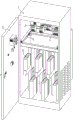
Fig. 1 is a schematic structural diagram of an intelligent reactive compensation distribution box according to the present utility model.
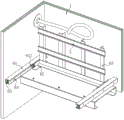
Fig. 2 is a three-dimensional schematic diagram of an adjustment assembly within a reactive compensation distribution box of the present utility model.
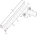
FIG. 3 is a three-dimensional schematic view of the internal structure of the tuning assembly.
Fig. 4 is a schematic front view of the elastic pad and the slide, pulley cooperation.
In the figure: 1. a cabinet body; 2. a cabinet door; 3. buckling a rail; 4. a power feeding element; 5. reactive capacitance; 6. an adjustment assembly; 61. a slide rail; 62. a slide; 63. a vertical frame; 64. a fixed rod; 65. twisting the handle; 621. a pulley; 64a, elastic pad.
Detailed Description
The technical solutions of the present utility model will be clearly and completely described below with reference to the accompanying drawings.
Examples: as shown in fig. 1-4, the utility model provides an intelligent reactive compensation distribution box, which structurally comprises a cabinet body 1 with cabinet doors 2, wherein the cabinet doors 2 are arranged on the front side and the rear side of the cabinet body 1, reactive capacitors 5 are arranged in the cabinet body 1 and are respectively arranged on the front side and the rear side of the cabinet body 1, the front cabinet door 2 and the rear cabinet door 2 respectively provide openings for the reactive capacitors 5 on the front side and the rear side of the cabinet body 1, an adjusting component 6 is arranged in an upper inlet wire area in the cabinet body 1, an electric inlet element 4 is arranged on the adjusting component 6, an introduced electric wire is connected with an inlet wire end of the electric inlet element 4, the electric inlet element 4 comprises electric elements such as a circuit breaker, an idle switch and the like, the reactive capacitors 5 are connected with the electric inlet element 4 through electric wires, a computer, a sensor and a communication technology are intelligently introduced, an intelligent algorithm is used for adjusting the running state of the capacitors, and the reactive compensation capacity and a control strategy are automatically controlled by analyzing data such as voltage, current and power factor.
Specifically, the adjusting component 6 includes a sliding rail 61 installed on two sides in the cabinet 1 and a sliding seat 62 slidably installed on the sliding rail 61, a stand 63 is installed on the sliding seat 62, a buckling rail 3 is transversely installed on the stand 63, and electric elements such as a circuit breaker of the power feeding element 4 and a free switch are installed on the buckling rail 3, so that the electric elements slide, the sliding seat 62 is provided with a plurality of pulleys 621 on two sides and the pulleys 621 are slidably assembled in the sliding rail 61, and in this embodiment, two pulleys 621 are respectively installed on two sides of the sliding seat 62.
Furthermore, a fixing rod 64 is installed between the vertical wall of the sliding rail 61 and the pulley 621, an elastic pad 64a is arranged on the fixing rod 64, the elastic pad 64a is in a convex shape on the cross section of the fixing rod 64, more specifically, the elastic pad 64a does not occupy the whole cylindrical range of the periphery of the fixing rod 64, but only occupies a part, the radius of the fixing rod 64 is smaller than the distance between the axis of the fixing rod 64 and the pulley 621, and the radius of the convex part of the elastic pad 64a on the fixing rod 64 is larger than the distance between the axis of the fixing rod 64 and the pulley 621.
As can be known by those skilled in the art, the fixing rods 64 are disposed in the sliding rails 61 on both sides, so that the fixing rods 64 on both sides cooperate to clamp the sliding seat 62, or the fixing rods 64 are disposed in the sliding rail 61 on one side only, so that the sliding seat 62 on the other side is directly abutted against the sliding rail 61 for fixing, and in this embodiment, the form of two sides is adopted.
In this embodiment, the fixing rod 64 is provided with a twisting handle 65 at the front end of the sliding rail 61, and as known to those skilled in the art, a pulling member such as a handle may be provided on the sliding seat 62 to facilitate the sliding of the sliding seat 62 on the sliding rail 61.
When the cabinet door 2 is opened, the rotary screwing handle 65 releases the state that the elastic pad 64a is abutted against the pulley 621, so that the clamping state of the elastic pad 64a on the sliding seat 62 is released, then the sliding seat 62 can be held, or the sliding seat 62 is grasped, the sliding seat 62 is pulled outwards, the sliding seat 62 slides on the sliding rail 61 through the pulley 621, after the required position is reached, the rotary screwing handle 65 is rotated, the elastic pad 64a is driven to be plugged between the fixed rod 64 and the pulley 621 through the rotation of the fixed rod 64 to be filled, so that the position of the sliding seat 62 is fixed through the pulley clamping, and at the moment, an overhaul worker can directly put the sliding seat 4 on the buckling rail 3 without the body or arm into the cabinet, and at the same time, the electric power distribution cabinet is not closed by the clamping state of the elastic pad 64a on the pulley 621, and the sliding seat 62 can be locked deeply after the overhaul 65 is opened, and the overhaul 65 is locked deeply after the overhaul is completed.
The technical features of the above-described embodiments may be arbitrarily combined, and all possible combinations of the technical features in the above-described embodiments are not described for brevity of description, however, as long as there is no contradiction between the combinations of the technical features, they should be considered as the scope of the description.
Claims (4)
1. The utility model provides an intelligent reactive compensation block terminal, its structure is including the cabinet body that has the cabinet door, the reactive capacitance has been installed to the internal portion of cabinet, reactive capacitance is connected its characterized in that with advancing electric element: an adjusting component is arranged in the wire inlet area at the upper end in the cabinet body, and the electric inlet element is arranged on the adjusting component;
the adjusting component comprises sliding rails arranged on two sides of the cabinet body and a sliding seat arranged on the sliding rails in a sliding manner, a vertical frame is arranged on the sliding seat, a buckling rail is arranged on the vertical frame, and the power feeding element is arranged on the buckling rail;
a plurality of pulleys are arranged on two sides of the sliding seat, and the pulleys are slidably assembled in the sliding rail;
a fixed rod is arranged between the vertical wall of the sliding rail and the pulley, an elastic pad is arranged on the fixed rod, and the elastic pad is in a convex shape on the cross section of the fixed rod.
2. An intelligent reactive compensation distribution box according to claim 1, characterized in that: the radius of the fixed rod is smaller than the distance between the axis of the fixed rod and the pulley;
the radius of the elastic pad protruding part on the fixed rod is larger than the distance between the axis of the fixed rod and the pulley.
3. An intelligent reactive compensation distribution box according to claim 1, characterized in that: the fixing rod is provided with a twisting handle at the front end of the sliding rail.
4. An intelligent reactive compensation distribution box according to claim 1, characterized in that: the length of the electric wire connected with the reactive capacitor by the power feeding element is provided with an activity allowance.
Priority Applications (1)
| Application Number | Priority Date | Filing Date | Title |
|---|---|---|---|
| CN202321074904.XU CN219123776U (en) | 2023-05-08 | 2023-05-08 | Intelligent reactive compensation distribution box |
Applications Claiming Priority (1)
| Application Number | Priority Date | Filing Date | Title |
|---|---|---|---|
| CN202321074904.XU CN219123776U (en) | 2023-05-08 | 2023-05-08 | Intelligent reactive compensation distribution box |
Publications (1)
| Publication Number | Publication Date |
|---|---|
| CN219123776U true CN219123776U (en) | 2023-06-02 |
Family
ID=86535466
Family Applications (1)
| Application Number | Title | Priority Date | Filing Date |
|---|---|---|---|
| CN202321074904.XU Active CN219123776U (en) | 2023-05-08 | 2023-05-08 | Intelligent reactive compensation distribution box |
Country Status (1)
| Country | Link |
|---|---|
| CN (1) | CN219123776U (en) |
Cited By (1)
| Publication number | Priority date | Publication date | Assignee | Title |
|---|---|---|---|---|
| CN118040512A (en) * | 2024-04-11 | 2024-05-14 | 宝利阳光(福建)新能源有限公司 | Intelligent reactive compensation distribution box |
-
2023
- 2023-05-08 CN CN202321074904.XU patent/CN219123776U/en active Active
Cited By (2)
| Publication number | Priority date | Publication date | Assignee | Title |
|---|---|---|---|---|
| CN118040512A (en) * | 2024-04-11 | 2024-05-14 | 宝利阳光(福建)新能源有限公司 | Intelligent reactive compensation distribution box |
| CN118040512B (en) * | 2024-04-11 | 2024-06-04 | 宝利阳光(福建)新能源有限公司 | Intelligent reactive compensation distribution box |
Similar Documents
| Publication | Publication Date | Title |
|---|---|---|
| CN219123776U (en) | Intelligent reactive compensation distribution box | |
| CN114047363B (en) | Remote monitoring device based on OCS system | |
| CN210693069U (en) | Outdoor high-voltage power distribution cabinet with high sealing performance | |
| CN209948411U (en) | Distribution equipment with full-electric-quantity energy efficiency management function | |
| CN210468389U (en) | Slidingtype switch board cable finishing device | |
| CN208046035U (en) | A kind of high-low voltage electric power distribution cabinet outer container | |
| CN210723806U (en) | Low-voltage draw-out type switch cabinet | |
| CN222706014U (en) | High-low voltage switch cabinet convenient to overhaul | |
| CN214013512U (en) | Intelligent door lock power distribution cabinet | |
| CN218828595U (en) | Distribution cabinet door and distribution cabinet with blocking function | |
| CN221226825U (en) | Micro-grid energy storage DC control cabinet | |
| CN207994349U (en) | One kind preventing switch cabinet electrified earthing or grounding means | |
| CN215579777U (en) | Intelligent power equipment power distribution cabinet | |
| CN206451996U (en) | A kind of anti-error type fixed high-voltage switch cubicle | |
| CN215221536U (en) | Low-voltage switch cabinet | |
| CN220754087U (en) | Electrical cabinet assembly rear plate convenient to overhaul | |
| CN220401110U (en) | Circuit storage structure | |
| CN216489153U (en) | Power distribution cabinet convenient for wiring | |
| CN216289537U (en) | Novel switch board of pull-out type | |
| CN220040638U (en) | Cable withstand voltage test platform | |
| CN222085511U (en) | Complete equipment for monitoring power transformation and distribution | |
| CN218940344U (en) | Distribution box for optical storage and filling integrated quick wiring | |
| CN216526186U (en) | Terminal detection equipment applied to power distribution network | |
| CN221885752U (en) | Draw-out type internet of things switch cabinet | |
| CN209626710U (en) | A kind of secondary line protection device of high-tension switch cabinet |
Legal Events
| Date | Code | Title | Description |
|---|---|---|---|
| GR01 | Patent grant | ||
| GR01 | Patent grant |