CN219112663U - Sheet metal part stamping die - Google Patents
Sheet metal part stamping die Download PDFInfo
- Publication number
- CN219112663U CN219112663U CN202223201228.6U CN202223201228U CN219112663U CN 219112663 U CN219112663 U CN 219112663U CN 202223201228 U CN202223201228 U CN 202223201228U CN 219112663 U CN219112663 U CN 219112663U
- Authority
- CN
- China
- Prior art keywords
- fixedly connected
- stamping die
- sheet metal
- motor
- metal part
- Prior art date
- Legal status (The legal status is an assumption and is not a legal conclusion. Google has not performed a legal analysis and makes no representation as to the accuracy of the status listed.)
- Active
Links
Images


Classifications
-
- Y—GENERAL TAGGING OF NEW TECHNOLOGICAL DEVELOPMENTS; GENERAL TAGGING OF CROSS-SECTIONAL TECHNOLOGIES SPANNING OVER SEVERAL SECTIONS OF THE IPC; TECHNICAL SUBJECTS COVERED BY FORMER USPC CROSS-REFERENCE ART COLLECTIONS [XRACs] AND DIGESTS
- Y02—TECHNOLOGIES OR APPLICATIONS FOR MITIGATION OR ADAPTATION AGAINST CLIMATE CHANGE
- Y02P—CLIMATE CHANGE MITIGATION TECHNOLOGIES IN THE PRODUCTION OR PROCESSING OF GOODS
- Y02P70/00—Climate change mitigation technologies in the production process for final industrial or consumer products
- Y02P70/10—Greenhouse gas [GHG] capture, material saving, heat recovery or other energy efficient measures, e.g. motor control, characterised by manufacturing processes, e.g. for rolling metal or metal working
Abstract
The utility model discloses a sheet metal part stamping die, wherein a motor I which is vertically upwards is fixedly connected to the bottom of a workbench, a rotating part is fixedly connected to the output end of the motor I, a motor II which is uniformly distributed is arranged on the rotating part, the output end of the motor II is fixedly connected with the stamping die, a fixing frame is fixedly connected to the upper part of the workbench, a hydraulic cylinder II which is vertically downwards is fixedly connected to the upper part of the fixing frame, a stamping plate is fixedly connected to the lower end of the hydraulic cylinder II, the stamping plate is matched with the stamping die, a hydraulic cylinder I which is vertically downwards is fixedly connected to the fixing frame, a knocking hammer is fixedly connected to the lower end of the hydraulic cylinder I, a blanking port is formed in the workbench under the knocking hammer, the motor I drives a plurality of uniformly distributed stamping dies to move, the hydraulic cylinder II can continuously process the sheet metal part, the hydraulic cylinder II drives the stamping die to overturn, and the knocking hammer drives the sheet metal part to drop off through the motor II, so that the continuous processing and automatic collecting functions of the sheet metal part are realized.
Description
Technical Field
The utility model relates to the technical field of stamping dies, in particular to a sheet metal part stamping die.
Background
The metal plate is a metal plate, is usually below 6mm, and is a comprehensive cold processing technology, comprising shearing, cutting, compounding, folding, riveting, splicing, forming and the like, and is characterized in that the thickness of the same part is consistent; the mould is used for producing various moulds and tools of the needed products by injection molding, blow molding, extrusion, die casting or forging, smelting, stamping and other methods in industry.
The current panel beating is on stamping forming's process is most firstly placing the panel beating on stamping die, carries out stamping forming to the panel beating through the top board, takes out the mould after stamping forming, carries out stamping work at the reentrant panel beating, and such processing mode makes unable continuous stamping work to the panel beating to lead to work efficiency subalternation, and the panel beating produces great friction with the mould easily after stamping forming, leads to taking out the difficulty, consequently proposes a sheet metal component stamping die for solve unable continuous operation and the problem that the panel beating was taken out the difficulty that exists among the current device.
Disclosure of Invention
The utility model aims to provide a sheet metal part stamping die, which is used for solving the problems of the sheet metal part stamping die in the background art.
In order to achieve the above purpose, the present utility model provides the following technical solutions: sheet metal component stamping die, the bottom fixedly connected with of workstation is vertical ascending motor I, the output fixedly connected with of motor I rotates the piece, be provided with evenly distributed's motor II on the rotation piece, the output fixedly connected with stamping die of motor II, the top fixedly connected with mount of workstation, the top fixedly connected with of mount is vertical decurrent pneumatic cylinder II, the lower extreme fixedly connected with stamping plate of pneumatic cylinder II, and stamping plate and stamping die looks adaptation, the vertical decurrent pneumatic cylinder I of fixedly connected with on the mount, the lower extreme fixedly connected with of pneumatic cylinder I beats the hammer, the blanking mouth has been seted up on the workstation under the hammer.
As a further preferable mode of the technical scheme, a rubber pad is fixedly connected to the lower end portion of the knocking hammer.
As a further preferable mode of the technical scheme, a plurality of guide rollers are rotatably connected below the blanking port, and the rollers are obliquely and uniformly arranged downwards.
As a further preferable mode of the technical scheme, a rubber ring is sleeved on the outer side of the material guiding roller.
As a further preferable mode of the technical scheme, the rotating piece is fixedly connected with a fixing seat, and the motor II is fixedly connected to the fixing seat.
As a further preferable mode of the technical scheme, a symmetrical circular chute is formed in the upper side of the workbench.
As a further preferable mode of the technical scheme, a symmetrical sliding block is fixedly connected to the lower side of the stamping die, and the sliding block is in sliding connection with the sliding groove.
The utility model provides a sheet metal part stamping die, which has the following beneficial effects:
(1) According to the utility model, through the arrangement of the motor I, the rotating part, the stamping die, the hydraulic cylinder II and the stamping plate, the motor I is started to drive the rotating part to rotate when the stamping die works, so that the stamping die is positioned right below the stamping plate, the hydraulic cylinder II drives the stamping plate to stamp and shape the sheet metal part in the stamping die, when the hydraulic cylinder drives the stamping plate to move upwards after stamping and shaping, the motor I drives the other stamping die to be positioned below the stamping plate, and the hydraulic cylinder II continuously drives the stamping plate to process the sheet metal part in the stamping die, so that the continuous processing function of the sheet metal part is realized, and the stamping and shaping efficiency of the sheet metal part is improved.
(2) According to the utility model, through the arrangement of the motor I, the motor II, the hydraulic cylinder I, the knocking hammer and the blanking port, after the sheet metal part is subjected to stamping forming, the motor I drives the stamping die to reach the position right above the blanking port, the motor II drives the stamping die to overturn downwards, and the hydraulic cylinder I drives the knocking hammer to knock the stamping die downwards, so that the sheet metal part falls off from the stamping die, and the automatic blanking function is realized.
Drawings
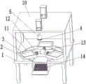
FIG. 1 is a schematic side view of a sheet metal part stamping die;
fig. 2 is a schematic diagram of a front view structure of a sheet metal part stamping die according to the present utility model;
FIG. 3 is an enlarged schematic view of the portion A of FIG. 1 according to the present utility model;
FIG. 4 is a schematic view of a partial cross-sectional structure of a blanking port in a sheet metal part stamping die according to the present utility model;
in the figure: 1. a work table; 2. a blanking port; 3. stamping die; 4. a rubber pad; 5. knocking a hammer; 6. a hydraulic cylinder I; 7. a motor I; 8. a stamping plate; 9. a hydraulic cylinder II; 10. a fixing frame; 11. a chute; 12. a motor II; 13. a rotating member; 14. a rubber ring; 15. a fixing seat; 16. a slide block; 17. and a material guiding roller.
Detailed Description
The technical solutions in the embodiments of the present utility model will be clearly and completely described below with reference to the accompanying drawings in the embodiments of the present utility model.
The utility model provides the technical scheme that: in this embodiment, as shown in fig. 1-3, the bottom fixedly connected with of workstation 1 is vertical ascending motor i 7, the output fixedly connected with of motor i 7 rotates piece 13, be provided with evenly distributed's motor ii 12 on the rotating piece 13, the output fixedly connected with stamping die 3 of motor ii 12, when motor i 7 starts, it is rotatory to drive rotating piece 13, make fixedly connected's stamping die 3 on motor ii 12 output be driven and remove, stamping die 3's downside fixedly connected with symmetrical slider 16, the upside of workstation 1 has seted up symmetrical circular spout 11, slider 16 and spout 11 sliding connection, can make stamping die 3 remove along the direction of spout 11 through the setting of slider 16 and spout 11, reduce the friction between stamping die 3 and the workstation 1, the top fixedly connected with mount 10 of workstation 1, the top fixedly connected with vertical decurrent pneumatic cylinder ii 9, the lower extreme fixedly connected with stamping plate 8 of pneumatic cylinder ii 9, and stamping plate 8 and stamping die 3 looks motor 3 drive the pneumatic cylinder ii when the stamping die 8 is right to the stamping die 8, the pneumatic cylinder ii is driven to the stamping plate 8 when the stamping die 8 is driven to the stamping plate 8, it makes stamping plate 8 to directly drive down to rotate to carry out the stamping die 8.
As shown in fig. 1, 2 and 4, a fixed seat 15 is fixedly connected on a rotating member 13, a motor II 12 is fixedly connected on the fixed seat 15, the motor II 12 and the rotating member 13 are fixedly connected through the arrangement of the fixed seat 15, a vertical downward hydraulic cylinder I6 is fixedly connected on the fixed seat 10, the lower end of the hydraulic cylinder I6 is fixedly connected with a knocking hammer 5, the lower end part of the knocking hammer 5 is fixedly connected with a rubber pad 4, a blanking hole 2 is arranged on a workbench 1 under the knocking hammer 5, when a stamping die 3 after the motor I7 drives the stamping forming reaches the position right above the blanking hole 2, the motor II 12 is started to drive the stamping die 3 to rotate 180 degrees, so that the sheet metal part faces to the blanking hole 2 at the lower side, the hydraulic cylinder I6 drives the knocking hammer 5 to move downward, strike stamping die 3 to drop the sheet metal component from stamping die 3 through vibrations, fall into in the blanking mouth 2 of below, through setting up of rubber pad 4, can make strike hammer 5 when striking stamping die 3, protect stamping die 3, the below rotation of blanking mouth 2 is connected with a plurality of guide rolls 17, and change the slope and evenly arrange downwards, guide roll 17's outside cover is equipped with rubber circle 14, when the sheet metal component drops out from stamping die 3, with rubber circle 14 contact, rubber circle 14 can cushion the sheet metal component, prevent to collide with and appear the damage, thereby drive sheet metal component downwardly moving through the guide roll 17 of slope homogeneous arrangement and realize collecting the function to the sheet metal component after the stamping.
The utility model provides a sheet metal part stamping die, which has the following specific working principle: during operation, through the rotation of motor I7, drive stamping die 3 and remove, thereby make the sheet metal component in the stamping die 3 arrive under the stamping plate 8, at this moment pneumatic cylinder II 9 starts, drive stamping plate 8 carries out stamping forming to the sheet metal component in the stamping die 3, after the punching press is accomplished, motor I7 continues to drive next stamping die 3 and reaches stamping plate 8 below, stamping plate 8 continues to carry out the punching press to the sheet metal component in stamping die 3, and the sheet metal component after last punching press is accomplished is driven to the top of blanking mouth 2 by motor I7, motor II 12 drives stamping die 3 rotation, make the sheet metal component in the stamping die 3 under towards, pneumatic cylinder I6 drives and beats 5 to strike stamping die 3, thereby make the sheet metal component in the stamping die 3 drop, get into in blanking mouth 2 and collect.
Although embodiments of the present utility model have been shown and described, it will be understood by those skilled in the art that various changes, modifications, substitutions and alterations can be made therein without departing from the principles and spirit of the utility model, the scope of which is defined in the appended claims and their equivalents.
Claims (7)
1. Sheet metal part stamping die, including workstation (1), its characterized in that: the automatic punching machine is characterized in that a motor I (7) is vertically upwards connected to the bottom of the workbench (1), a rotating part (13) is fixedly connected to the output end of the motor I (7), a motor II (12) which is evenly distributed is arranged on the rotating part (13), a punching die (3) is fixedly connected to the output end of the motor II (12), a fixing frame (10) is fixedly connected to the upper portion of the workbench (1), a hydraulic cylinder II (9) is vertically downwards connected to the upper portion of the fixing frame (10), a punching plate (8) is fixedly connected to the lower end of the hydraulic cylinder II (9), the punching plate (8) is matched with the punching die (3), a hydraulic cylinder I (6) is vertically downwards connected to the fixing frame (10), a knocking hammer (5) is fixedly connected to the lower end of the hydraulic cylinder I (6), and a blanking port (2) is formed in the workbench (1) right below the knocking hammer (5).
2. The sheet metal part stamping die of claim 1, wherein: the lower end part of the knocking hammer (5) is fixedly connected with a rubber pad (4).
3. The sheet metal part stamping die of claim 1, wherein: the lower part of the blanking port (2) is rotationally connected with a plurality of material guiding rollers (17), and the material guiding rollers are obliquely and downwards uniformly arranged.
4. A sheet metal part stamping die as defined in claim 3, wherein: the outer side of the material guiding roller (17) is sleeved with a rubber ring (14).
5. The sheet metal part stamping die of claim 1, wherein: the rotating piece (13) is fixedly connected with a fixing seat (15), and the motor II (12) is fixedly connected to the fixing seat (15).
6. The sheet metal part stamping die of claim 1, wherein: the upper side of the workbench (1) is provided with symmetrical circular sliding grooves (11).
7. The sheet metal part stamping die of claim 1, wherein: the lower side of the stamping die (3) is fixedly connected with symmetrical sliding blocks (16), and the sliding blocks (16) are in sliding connection with the sliding grooves (11).
Priority Applications (1)
| Application Number | Priority Date | Filing Date | Title |
|---|---|---|---|
| CN202223201228.6U CN219112663U (en) | 2022-11-30 | 2022-11-30 | Sheet metal part stamping die |
Applications Claiming Priority (1)
| Application Number | Priority Date | Filing Date | Title |
|---|---|---|---|
| CN202223201228.6U CN219112663U (en) | 2022-11-30 | 2022-11-30 | Sheet metal part stamping die |
Publications (1)
| Publication Number | Publication Date |
|---|---|
| CN219112663U true CN219112663U (en) | 2023-06-02 |
Family
ID=86524121
Family Applications (1)
| Application Number | Title | Priority Date | Filing Date |
|---|---|---|---|
| CN202223201228.6U Active CN219112663U (en) | 2022-11-30 | 2022-11-30 | Sheet metal part stamping die |
Country Status (1)
| Country | Link |
|---|---|
| CN (1) | CN219112663U (en) |
-
2022
- 2022-11-30 CN CN202223201228.6U patent/CN219112663U/en active Active
Similar Documents
| Publication | Publication Date | Title |
|---|---|---|
| CN201456448U (en) | Punch press feeding device | |
| CN210676615U (en) | Combined die safety protection device | |
| CN216540376U (en) | Continuous stamping die for forming aluminum shell | |
| CN219112663U (en) | Sheet metal part stamping die | |
| CN218224412U (en) | Full-automatic blanking and punching die | |
| CN219233674U (en) | Multistation integration stamping mechanism | |
| CN217095386U (en) | Stamping lathe for machine manufacturing | |
| CN113634708B (en) | Gear blank forging device for preventing gear machining metal raw material from being loose in as-cast state | |
| CN211386491U (en) | Punching machine blanking device | |
| CN214263565U (en) | Large-sized workpiece feeding and knockout die with automatic material receiving device | |
| CN213002200U (en) | Stamping die is used in processing of efficient transformer | |
| CN214768347U (en) | A stamping device for dull and stereotyped metal-back CNC processing | |
| CN215040582U (en) | Full-automatic high-speed rotary tablet press | |
| CN212822306U (en) | Button stamping forming device | |
| CN108127052A (en) | A kind of double acting compound die cup press of high production and its cup stamping technique | |
| CN211707962U (en) | Workpiece taking-out device for stamping die | |
| CN210329483U (en) | Dotter convenient to unloading | |
| CN207839899U (en) | A kind of double acting compound die cup press of high production | |
| CN215544378U (en) | Quick processingequipment that case towards mould was used | |
| CN219401942U (en) | Mould convenient to get material | |
| CN219924351U (en) | Automatic material loading formula piercing press | |
| CN215392155U (en) | Intelligent punching machine | |
| CN218903243U (en) | Processing punch press capable of automatically collecting waste materials | |
| CN210253794U (en) | Quick die filling platform with forward feeding and discharging holes | |
| CN214726782U (en) | Automatic feeding structure of four-column hydraulic press |
Legal Events
| Date | Code | Title | Description |
|---|---|---|---|
| GR01 | Patent grant | ||
| GR01 | Patent grant |