CN219111352U - Double-shaft spiral stirring equipment for compound fertilizer production - Google Patents
Double-shaft spiral stirring equipment for compound fertilizer production Download PDFInfo
- Publication number
- CN219111352U CN219111352U CN202320091966.5U CN202320091966U CN219111352U CN 219111352 U CN219111352 U CN 219111352U CN 202320091966 U CN202320091966 U CN 202320091966U CN 219111352 U CN219111352 U CN 219111352U
- Authority
- CN
- China
- Prior art keywords
- main shaft
- stirring
- shaft
- discharging
- cylinder
- Prior art date
- Legal status (The legal status is an assumption and is not a legal conclusion. Google has not performed a legal analysis and makes no representation as to the accuracy of the status listed.)
- Active
Links
Images
Classifications
-
- Y—GENERAL TAGGING OF NEW TECHNOLOGICAL DEVELOPMENTS; GENERAL TAGGING OF CROSS-SECTIONAL TECHNOLOGIES SPANNING OVER SEVERAL SECTIONS OF THE IPC; TECHNICAL SUBJECTS COVERED BY FORMER USPC CROSS-REFERENCE ART COLLECTIONS [XRACs] AND DIGESTS
- Y02—TECHNOLOGIES OR APPLICATIONS FOR MITIGATION OR ADAPTATION AGAINST CLIMATE CHANGE
- Y02W—CLIMATE CHANGE MITIGATION TECHNOLOGIES RELATED TO WASTEWATER TREATMENT OR WASTE MANAGEMENT
- Y02W30/00—Technologies for solid waste management
- Y02W30/40—Bio-organic fraction processing; Production of fertilisers from the organic fraction of waste or refuse
Landscapes
- Mixers Of The Rotary Stirring Type (AREA)
Abstract
The utility model provides double-shaft spiral stirring equipment for compound fertilizer production, wherein one end of a stirring cylinder is in butt joint with a discharging cylinder, and the tail end of the discharging cylinder is provided with a discharging door structure in a sliding manner through a sliding rail; the stirring cylinder body and the discharging cylinder body are internally provided with a first main shaft and a second main shaft in parallel, one ends of the first main shaft and the second main shaft are rotatably supported in the bearing seat structure, the other ends of the first main shaft and the second main shaft are connected with a synchronous gear box body, and the synchronous gear box body is fixed at the bottom end of the top mounting frame; the synchronous gear box body is connected with the power device; the first main shaft and the second main shaft are provided with stirring blades at one section of length inside the stirring cylinder, and a discharging spiral blade is provided at one section of length inside the discharging cylinder. The stirring equipment adopts a double-shaft synchronous stirring mode, so that the full mixing and stirring of materials in the fertilizer preparation process are ensured.
Description
Technical Field
The utility model belongs to the field of fertilizer production, and particularly relates to double-shaft spiral stirring equipment for compound fertilizer production.
Background
In the production process of the compound fertilizer, different types of raw materials and different types of raw materials are required to be mixed firstly, and after the raw materials and the raw materials are mixed fully, the subsequent granulation process is carried out.
At present, in the process of mixing raw materials, a mixer adopted is mainly a single-shaft mixer. In the use process, the problems are that: (1) The single-shaft stirrer is insufficient in material mixing, so that the quality of the finally prepared fertilizer is influenced, and the granulating effect is influenced; (2) Because the unipolar mixer mainly plays the stirring effect, in the stirring completion need discharge in-process, owing to do not have ejection of compact helical blade, the material is at the discharge in-process, need to unload repeatedly and just can accomplish the discharge of material.
Disclosure of Invention
In order to solve the technical problems, the utility model provides the double-shaft spiral stirring equipment for producing the compound fertilizer, which adopts a double-shaft synchronous stirring mode, so that the full mixing and stirring of materials in the fertilizer preparation process are ensured, the material mixing effect is ensured, and the quality of the prepared fertilizer is further ensured; in addition, through the structure that increases ejection of compact spiral at the ejection of compact end, made things convenient for the quick discharge of material after the stirring is accomplished, improved ejection of compact efficiency.
In order to achieve the technical characteristics, the aim of the utility model is realized in the following way: the double-shaft spiral stirring equipment for producing the compound fertilizer comprises a stirring barrel, wherein one end of the stirring barrel is in butt joint with a discharging barrel, and the tail end of the discharging barrel is provided with a discharging door structure in a sliding manner through a sliding rail; the stirring cylinder body and the discharging cylinder body are internally provided with a first main shaft and a second main shaft in parallel, one ends of the first main shaft and the second main shaft are rotatably supported in the bearing seat structure, the other ends of the first main shaft and the second main shaft are connected with a synchronous gear box body for driving the first main shaft and the second main shaft to synchronously rotate, and the synchronous gear box body is fixed at the bottom end of the top mounting frame; the synchronous gear box body is connected with a power device for driving the synchronous gear box body to rotate; the first main shaft and the second main shaft are provided with stirring blades at one section of length inside the stirring cylinder, and a discharging spiral blade is provided at one section of length inside the discharging cylinder.
The bottom end of the stirring cylinder is provided with a cylinder base; the top end of the stirring cylinder adopts an opening structure.
The stirring cylinder body and the discharging cylinder body are in butt joint connection through a flange connecting seat.
The discharging door structure comprises a grid door which is slidably arranged between the sliding rails, the grid door is hinged with a door body oil cylinder for driving the grid door to slide, a cylinder body base of the door body oil cylinder is hinged on a cylinder body mounting seat, and the cylinder body mounting seat is fixed at the tail end of the discharging cylinder body.
The bearing seat structure comprises a bearing seat connecting seat, wherein the bearing seat connecting seat is fixed at the bottom end of the top mounting frame, the bottom end of the bearing seat connecting seat is fixedly provided with a bearing seat, an angular contact bearing and a thrust ball bearing which are used for rotatably supporting the corresponding first main shaft and second main shaft are arranged in the bearing seat, the angular contact bearing is positioned through an inner bearing end cover, the thrust ball bearing is fixed with a bearing shield through an outer bearing retainer ring and a round nut, and the outer end face of the bearing seat is fixedly provided with a bearing shield.
The power device comprises a driving belt pulley, the driving belt pulley is arranged on an input shaft of the speed reducer, and an output shaft of the speed reducer is connected with an input shaft of the synchronous gear box body through a coupler; when the belt conveyer works, the driving belt pulley is connected with the motor through the belt and transmits power.
The synchronous gear box comprises a gear box body, the gear box body is fixedly connected with a top mounting frame through a box body connecting seat, a driving gear and a driven gear which are meshed with each other are parallelly arranged in the gear box body, the driving gear is arranged on a first main shaft, and the driven gear is arranged on a second main shaft.
A section of length, which is positioned inside the stirring cylinder body, of the first main shaft and the second main shaft is provided with a stirring rod;
the discharging cylinder is fixedly connected with the top mounting frame through a cylinder rib plate.
And the first main shaft and the second main shaft are provided with radiating blades at the ends of the bearing seat structures.
The utility model has the following beneficial effects:
1. by adopting the stirring equipment provided by the utility model, a double-shaft synchronous stirring mode is adopted, so that the full mixing and stirring of materials in the fertilizer preparation process are ensured, the material mixing effect is ensured, and the quality of the prepared fertilizer is further ensured; in addition, through the structure that increases ejection of compact spiral at the ejection of compact end, made things convenient for the quick discharge of material after the stirring is accomplished, improved ejection of compact efficiency.
2. The barrel base can be used for reliably supporting and fixing the stirring barrel, so that the reliability and stability of the structure of the stirring barrel are guaranteed.
3. Reliable butt joint between the stirring barrel and the discharging barrel can be realized through the flange connecting seat, so that the stirring and mixing of materials and discharging operation can be realized conveniently.
4. The discharging door structure is convenient for control the discharging process, and further automatic discharging control of materials is realized.
5. The bearing seat structure can realize the rotation support of the first main shaft and the second main shaft, ensure that the corresponding first main shaft and the second main shaft can bear corresponding axial force and radial force, and ensure that the first main shaft and the second main shaft can smoothly rotate.
6. The power device can be used for providing stirring power.
7. The synchronous gearbox body can be used for synchronously driving the first main shaft and the second main shaft to synchronously rotate, so that double-shaft stirring is realized, and mixing quality and efficiency are improved.
Drawings
The utility model is further described below with reference to the drawings and examples.
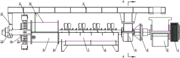
Fig. 1 is a front view of the present utility model.
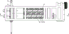
Fig. 2 is a top view of the present utility model.
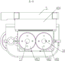
Fig. 3 is a view A-A of fig. 1 in accordance with the present utility model.
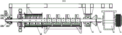
Fig. 4 is a view B-B of fig. 2 in accordance with the present utility model.
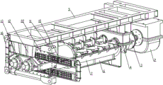
Fig. 5 is a first perspective three-dimensional view of the present utility model.
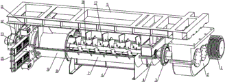
Fig. 6 is a second perspective three-dimensional view of the present utility model.
In the figure: the device comprises a driving pulley 1, a speed reducer 2, a shaft coupling 3, a synchronous gear box 4, a top mounting frame 5, a cylinder base 6, a stirring cylinder 7, a flange connecting seat 8, a discharging cylinder 9, a cylinder rib plate 10, a door cylinder 11, a bearing seat connecting seat 12, a bearing seat structure 13, cooling blades 14, a grid door 15, a cylinder body mounting seat 16, a second main shaft 17, a first main shaft 18, a stirring rod 19, stirring blades 20, discharging spiral blades 21 and a sliding rail 22;
a gear housing 401, a driving gear 402, a driven gear 403, and a housing connection base 404;
angular contact bearing 1301, bearing housing 1302, thrust ball bearing 1303, round nut 1304, bearing shield 1305, outboard bearing retainer 1306, inboard bearing end cap 1307.
Detailed Description
Embodiments of the present utility model will be further described with reference to the accompanying drawings.
Referring to fig. 1-6, the double-shaft spiral stirring equipment for compound fertilizer production comprises a stirring cylinder 7, wherein one end of the stirring cylinder 7 is in butt joint with a discharging cylinder 9, and the tail end of the discharging cylinder 9 is slidably provided with a discharging door structure through a sliding rail 22; the stirring cylinder 7 and the discharging cylinder 9 are internally provided with a first main shaft 18 and a second main shaft 17 in parallel, one ends of the first main shaft 18 and the second main shaft 17 are rotatably supported in the bearing seat structure 13, the other ends of the first main shaft 18 and the second main shaft 17 are connected with a synchronous gear box body 4 for driving the synchronous gear box body to rotate synchronously, and the synchronous gear box body 4 is fixed at the bottom end of the top mounting frame 5; the synchronous gear box body 4 is connected with a power device for driving the synchronous gear box body to rotate; the first main shaft 18 and the second main shaft 17 are provided with stirring blades 20 at a length of the inside of the stirring cylinder 7, and a discharging spiral blade 21 at a length of the inside of the discharging cylinder 9. The stirring equipment adopts a double-shaft synchronous stirring mode, so that the full mixing and stirring of materials in the fertilizer preparation process are ensured, the material mixing effect is ensured, and the quality of the prepared fertilizer is further ensured; in addition, through the structure that increases ejection of compact spiral at the ejection of compact end, made things convenient for the quick discharge of material after the stirring is accomplished, improved ejection of compact efficiency. In the concrete working process, the synchronous gear box body 4 is driven by the power device, the first main shaft 18 and the second main shaft 17 are synchronously driven by the synchronous gear box body 4, the stirring blades 20 are driven by synchronous rotation of the first main shaft 18 and the second main shaft 17, the stirring of raw materials is synchronously realized by the stirring blades 20, the mixing effect of the raw materials is further ensured, and after the mixing is finished, the materials are discharged by the discharging cylinder 9, so that the automatic discharging process is realized.
Further, a barrel base 6 is arranged at the bottom end of the stirring barrel 7; the top end of the stirring cylinder 7 adopts an opening structure. The barrel base 6 can be used for reliably supporting and fixing the stirring barrel 7, so that the reliability and stability of the structure of the stirring barrel are ensured.
Further, the stirring cylinder 7 and the discharging cylinder 9 are in butt joint connection through a flange connecting seat 8. Reliable butt joint between the stirring barrel 7 and the discharging barrel 9 can be realized through the flange connecting seat 8, so that the stirring and mixing of materials and discharging operation can be realized conveniently.
Further, the discharging door structure comprises a grid door 15 which is slidably arranged between the sliding rails 22, the grid door 15 is hinged with a door body oil cylinder 11 for driving the grid door to slide, a cylinder body base of the door body oil cylinder 11 is hinged on a cylinder body mounting seat 16, and the cylinder body mounting seat 16 is fixed at the tail end of the discharging cylinder body 9. The discharging door structure is convenient for control the discharging process, and further automatic discharging control of materials is realized. In the working process, when the discharging process is needed, the grid door 15 is controlled to slide along the slide rail 22 through the door body oil cylinder 11, so that the grid door 15 is opened, and after the grid door is opened, materials are discharged from the outlet of the discharging cylinder 9, so that the discharging process is realized.
Further, the bearing seat structure 13 includes a bearing seat connecting seat 12, the bearing seat connecting seat 12 is fixed at the bottom end of the top mounting frame 5, a bearing seat 1302 is fixed at the bottom end of the bearing seat connecting seat 12, an angular contact bearing 1301 and a thrust ball bearing 1303 for rotatably supporting the corresponding first spindle 18 and second spindle 17 are disposed in the bearing seat 1302, the angular contact bearing 1301 is positioned through an inner bearing end cover 1307, the thrust ball bearing 1303 is fixed through an outer bearing retainer ring 1306 and a round nut 1304, and a bearing shield 1305 is fixed on the outer end face of the bearing seat 1302. The bearing seat structure 13 can realize the rotation support of the first main shaft 18 and the second main shaft 17, ensure that the corresponding first main shaft 18 and the second main shaft 17 can bear corresponding axial force and radial force, and ensure that the first main shaft 18 and the second main shaft 17 can smoothly rotate.
Further, the power device comprises a driving belt pulley 1, wherein the driving belt pulley 1 is arranged on an input shaft of a speed reducer 2, and an output shaft of the speed reducer 2 is connected with an input shaft of a synchronous gear box body 4 through a coupling 3; in operation, the driving pulley 1 is connected with the motor through a belt and transmits power. The power device can be used for providing stirring power. In the working process, the driving belt wheel 1 is driven by the motor, the speed reducer 2 is driven by the driving belt wheel 1, the coupler 3 is driven by the speed reducer 2, the synchronous gear box body 4 is driven by the coupler 3, and the first main shaft 18 and the second main shaft 17 are driven to synchronously rotate by the synchronous gear box body 4.
Further, the synchronous gear housing 4 includes a gear housing 401, the gear housing 401 is fixedly connected with the top mounting frame 5 through a housing connecting seat 404, a driving gear 402 and a driven gear 403 which are meshed with each other are installed in parallel in the gear housing 401, the driving gear 402 is installed on the first main shaft 18, and the driven gear 403 is installed on the second main shaft 17. The first main shaft 18 and the second main shaft 17 can be synchronously driven to synchronously rotate through the synchronous gear box body 4, so that double-shaft stirring is realized, and the mixing quality and efficiency are improved. In the working process, the driving gear 402 is driven to rotate through the speed reducer 2, the driven gear 403 is synchronously driven through the driving gear 402, and then the first main shaft 18 and the second main shaft 17 are synchronously driven to rotate through the driving gear 402 and the driven gear 403.
Further, stirring rods 19 are provided on the first main shaft 18 and the second main shaft 17 and located on a length of the inside of the stirring cylinder 7. Synchronous stirring is realized in the mixing process through the stirring rod 19, and the mixing effect is improved.
Further, the discharging cylinder 9 is fixedly connected with the top mounting frame 5 through a cylinder rib plate 10. The stability and reliability of the fixed installation of the discharging cylinder 9 are ensured through the cylinder rib plates 10.
Further, the first spindle 18 and the second spindle 17 are provided with cooling fins 14 at the ends of the bearing support structure 13. Through the above-mentioned radiating vane 14, the rotation of the first main shaft 18 and the second main shaft 17 can be synchronously driven in the rotation process, and then a certain ventilation and heat dissipation effect is achieved.
The application process of the utility model is as follows:
by adopting the double-shaft spiral stirring equipment, in the preparation process of the compound fertilizer, firstly, required raw materials are put into a stirring cylinder 7, then, a power device is started, a driving belt pulley 1 is driven by a motor, a speed reducer 2 is driven by the driving belt pulley 1, a coupler 3 is driven by the speed reducer 2, a synchronous gear box 4 is driven by the coupler 3, a driven gear 403 is synchronously driven by a driving gear 402, and a first main shaft 18 and a second main shaft 17 are synchronously driven to synchronously rotate by the driving gear 402 and the driven gear 403; the stirring blades 20 are driven by synchronous rotation of the first main shaft 18 and the second main shaft 17, raw material stirring is realized by the synchronous rotation of the stirring blades 20, after the stirring and mixing are completed, the grid door 15 is controlled to slide along the sliding rail 22 by the door cylinder 11 in the process of discharging, the grid door 15 is further opened, after the grid door 15 is opened, the first main shaft 18 and the second main shaft 17 drive the discharging spiral blades 21, the materials are discharged from the outlet of the discharging cylinder 9 by the discharging spiral blades 21, and the discharging process is realized.
Claims (9)
1. Double-shaft spiral stirring equipment for compound fertilizer production is characterized in that: the stirring device comprises a stirring cylinder body (7), wherein one end of the stirring cylinder body (7) is in butt joint with a discharging cylinder body (9), and the tail end of the discharging cylinder body (9) is provided with a discharging door structure in a sliding manner through a sliding rail (22); a first main shaft (18) and a second main shaft (17) are arranged in parallel in the stirring cylinder body (7) and the discharging cylinder body (9), one ends of the first main shaft (18) and the second main shaft (17) are rotatably supported in the bearing seat structure (13), the other ends of the first main shaft (18) and the second main shaft (17) are connected with a synchronous gear box body (4) for driving the synchronous gear box body to rotate synchronously, and the synchronous gear box body (4) is fixed at the bottom end of the top mounting frame (5); the synchronous gear box body (4) is connected with a power device for driving the synchronous gear box body to rotate; the first main shaft (18) and the second main shaft (17) are provided with stirring blades (20) at a section of the length inside the stirring cylinder (7), and a section of the length inside the discharging cylinder (9) is provided with discharging spiral blades (21).
2. The dual-shaft spiral stirring apparatus for compound fertilizer production of claim 1, wherein: the bottom end of the stirring cylinder (7) is provided with a cylinder base (6); the top end of the stirring cylinder body (7) adopts an opening structure.
3. The dual-shaft spiral stirring apparatus for compound fertilizer production of claim 1, wherein: the stirring cylinder body (7) is in butt joint connection with the discharging cylinder body (9) through a flange connecting seat (8).
4. The dual-shaft spiral stirring apparatus for compound fertilizer production of claim 1, wherein: the discharging door structure comprises a grid door (15) which is slidably arranged between sliding rails (22), the grid door (15) is hinged with a door body oil cylinder (11) for driving the grid door to slide, a cylinder body base of the door body oil cylinder (11) is hinged on a cylinder body mounting seat (16), and the cylinder body mounting seat (16) is fixed at the tail end of the discharging cylinder body (9).
5. The dual-shaft spiral stirring apparatus for compound fertilizer production of claim 1, wherein: the bearing seat structure (13) comprises a bearing seat connecting seat (12), the bearing seat connecting seat (12) is fixed at the bottom end of the top installation frame (5), a bearing seat (1302) is fixed at the bottom end of the bearing seat connecting seat (12), an angular contact bearing (1301) and a thrust ball bearing (1303) which are used for rotatably supporting a corresponding first main shaft (18) and second main shaft (17) are arranged in the bearing seat (1302), the angular contact bearing (1301) is positioned through an inner bearing end cover (1307), the thrust ball bearing (1303) is fixed through an outer bearing retainer ring (1306) and a round nut (1304), and a bearing shield (1305) is fixed on the outer end face of the bearing seat (1302).
6. The dual-shaft spiral stirring apparatus for compound fertilizer production of claim 1, wherein: the power device comprises a driving belt wheel (1), wherein the driving belt wheel (1) is arranged on an input shaft of a speed reducer (2), and an output shaft of the speed reducer (2) is connected with an input shaft of a synchronous gear box body (4) through a coupler (3); when the device works, the driving belt wheel (1) is connected with the motor through a belt and transmits power.
7. The double-shaft spiral stirring apparatus for producing compound fertilizer according to claim 1 or 6, wherein: the synchronous gear box body (4) comprises a gear box body (401), the gear box body (401) is fixedly connected with the top installation frame (5) through a box body connecting seat (404), a driving gear (402) and a driven gear (403) which are meshed with each other are arranged in parallel in the gear box body (401), the driving gear (402) is arranged on the first main shaft (18), and the driven gear (403) is arranged on the second main shaft (17).
8. The dual-shaft spiral stirring apparatus for compound fertilizer production of claim 1, wherein: a stirring rod (19) is arranged on the first main shaft (18) and the second main shaft (17) and positioned on a section of length inside the stirring cylinder (7);
the discharging cylinder body (9) is fixedly connected with the top mounting frame (5) through a cylinder body rib plate (10).
9. The dual-shaft spiral stirring apparatus for compound fertilizer production of claim 1, wherein: the first main shaft (18) and the second main shaft (17) are provided with radiating blades (14) at the end of the bearing seat structure (13).
Priority Applications (1)
| Application Number | Priority Date | Filing Date | Title |
|---|---|---|---|
| CN202320091966.5U CN219111352U (en) | 2023-01-31 | 2023-01-31 | Double-shaft spiral stirring equipment for compound fertilizer production |
Applications Claiming Priority (1)
| Application Number | Priority Date | Filing Date | Title |
|---|---|---|---|
| CN202320091966.5U CN219111352U (en) | 2023-01-31 | 2023-01-31 | Double-shaft spiral stirring equipment for compound fertilizer production |
Publications (1)
| Publication Number | Publication Date |
|---|---|
| CN219111352U true CN219111352U (en) | 2023-06-02 |
Family
ID=86535956
Family Applications (1)
| Application Number | Title | Priority Date | Filing Date |
|---|---|---|---|
| CN202320091966.5U Active CN219111352U (en) | 2023-01-31 | 2023-01-31 | Double-shaft spiral stirring equipment for compound fertilizer production |
Country Status (1)
| Country | Link |
|---|---|
| CN (1) | CN219111352U (en) |
-
2023
- 2023-01-31 CN CN202320091966.5U patent/CN219111352U/en active Active
Similar Documents
| Publication | Publication Date | Title |
|---|---|---|
| CN111514784A (en) | Agitating unit is used to medicine intermediate system | |
| CN219111352U (en) | Double-shaft spiral stirring equipment for compound fertilizer production | |
| CN220071452U (en) | Raw material mixing device | |
| CN211194400U (en) | Concrete mixer for building | |
| CN217068619U (en) | A mixer for refractory material production | |
| CN211159363U (en) | Mixing arrangement is used in processing of pure polyester powder coating | |
| CN213408355U (en) | Tiltable mixing device for food processing | |
| CN220940413U (en) | Mud making machine is used in production of taro circle | |
| CN215428586U (en) | Film and granular material stirrer | |
| CN220091086U (en) | Chemical filler mixing stirring device | |
| CN221207711U (en) | V-shaped metal powder mixer | |
| CN218962318U (en) | Compound jar with circulation stirring function | |
| CN221561878U (en) | Automatic batching device for brake disc processing | |
| CN220514023U (en) | Stirring mechanism of groove type mixer | |
| CN219596353U (en) | Degradation plastic granules mixes mixer | |
| CN213226963U (en) | But automatic discharge concrete mixer | |
| CN221756542U (en) | Full agitating unit of BMC resin lump material | |
| CN220610262U (en) | Intestinal flora granule preparation facilities | |
| CN219631087U (en) | High-efficient mixer | |
| CN221641329U (en) | Raw material mixing device of cement prefabricated part | |
| CN218985256U (en) | Premixed concrete admixture homogenizing device | |
| CN219543615U (en) | Mortar pool capable of automatically discharging | |
| CN218901471U (en) | Mixer that can go up unloading automatically | |
| CN218688646U (en) | Spiral double-shaft mixer for feed mixing | |
| CN217042325U (en) | Homogenizing mixer for producing macroelement water-soluble fertilizer |
Legal Events
| Date | Code | Title | Description |
|---|---|---|---|
| GR01 | Patent grant | ||
| GR01 | Patent grant |