CN219097428U - Control box convenient to operate - Google Patents
Control box convenient to operate Download PDFInfo
- Publication number
- CN219097428U CN219097428U CN202223223424.3U CN202223223424U CN219097428U CN 219097428 U CN219097428 U CN 219097428U CN 202223223424 U CN202223223424 U CN 202223223424U CN 219097428 U CN219097428 U CN 219097428U
- Authority
- CN
- China
- Prior art keywords
- fixed
- base
- transmission
- connecting plate
- block
- Prior art date
- Legal status (The legal status is an assumption and is not a legal conclusion. Google has not performed a legal analysis and makes no representation as to the accuracy of the status listed.)
- Active
Links
Images


Abstract
The utility model relates to the technical field of electric power products, in particular to a control box convenient to operate. The lifting mechanism is characterized by comprising a box door, a box body and a hinge, wherein one side of the box door is connected with one side of the box body through the hinge, a fixed base is fixed at the bottom of the box body, and a lifting mechanism for adjusting the height is arranged at the bottom of the fixed base; the lifting mechanism comprises a first fixed block, a fixed plate, a first connecting rod, a second connecting plate, a transmission base and a driving shaft, wherein one side of the first connecting rod is rotationally connected with the second connecting rod, one end of the first connecting rod is rotationally connected with the first connecting plate, and the top of the first connecting plate is fixed with the fixed plate. According to the utility model, through the cooperation of the fixed base, the lifting mechanism, the first fixed block and the positioning mechanism, the height of the control box can be conveniently adjusted according to the needs when the control box is used, and the fixed base and the first fixed block can be fixed more firmly according to the positioning mechanism.
Description
Technical Field
The utility model relates to the technical field of electric power products, in particular to a control box convenient to operate.
Background
Often install on site according to user's specific condition in the electric power supply installation, need to combine different subassemblies, work efficiency is low, because the restriction of place, time, personnel often appears the construction hidden danger in the field construction, the contact is not good, the easy stolen electric problem, and its degree of safety of current novel control box for the power supply can not satisfy people's demand far away.
In the patent with the publication number of CN206685757U, the novel control box for power supply solves the problems that the existing control box is inconvenient to move and lift when in use, and has poor heat dissipation effect, but the control box is not convenient to adjust the height according to the requirement when in use;
in summary, the following technical problems exist in the prior art: the existing control box is inconvenient to adjust the height according to the requirement when in use, and therefore, the control box convenient to operate is designed and used for solving the technical problem.
Disclosure of Invention
The utility model aims to provide a control box convenient to operate, which aims at the technical problems: the existing control box is inconvenient to adjust the height according to the requirement when in use.
In order to solve the technical problems, the utility model adopts the following technical scheme:
the control box convenient to operate comprises a box door, a box body and a hinge, wherein one side of the box door is connected with one side of the box body through the hinge, a fixed base is fixed at the bottom of the box body,
the internal mounting of unable adjustment base has the positioning mechanism who is used for carrying out spacing, positioning mechanism includes positioning shell, buckle and reset spring, the inside sliding connection of positioning shell one end has the buckle, the inclined plane has been seted up to the one end of buckle, the inside of positioning shell just is located the one end of buckle and is fixed with reset spring.
Preferably, the positioning mechanism comprises a guide block, a rack, a first motor and a transmission gear, wherein the bottom of the first motor is fixed with a fixed base, the output end of the first motor is connected with the transmission gear, the two sides of the transmission gear are connected with the rack in a meshed manner, one end of the rack away from the transmission gear is fixed with the guide block, and the bottom of the guide block is fixed with the positioning shell.
Preferably, the elevating system who is used for carrying out altitude mixture control is installed to unable adjustment base's bottom, elevating system includes first fixed block, fixed plate, first connecting plate, head rod and second connecting rod, one side rotation of head rod is connected with the second connecting rod, the one end rotation of head rod is connected with first connecting plate, the top of head rod is fixed with the fixed plate, the both ends at fixed plate top all are fixed with first fixed block, just first fixed block and unable adjustment base sliding connection.
Preferably, the lifting mechanism comprises a second connecting plate, a transmission base and a driving shaft, one end of the second connecting rod is rotationally connected with the second connecting plate, the transmission base is fixed at the bottom of the second connecting plate, the driving shafts are rotationally connected with the inside of the other ends of the first connecting rod and the second connecting rod, one driving shaft is in sliding connection with the first connecting plate, and the other driving shaft is in sliding connection with the second connecting plate.
Preferably, a transmission assembly for driving the driving shaft to move is further installed in the transmission base, the transmission assembly comprises a second motor, a first bevel gear, a second bevel gear, a transmission shaft and a third connecting plate, the transmission shaft is rotationally connected in the transmission base, a threaded section is formed in the outer side of one end of the transmission shaft, the third connecting plate is in threaded connection with the outer side of the threaded section, the third connecting plate is in sliding connection with the transmission base, and the top of the third connecting plate is fixed with the other driving shaft;
the inside of transmission base still is fixed with the second motor, the output of second motor is connected with first bevel gear, the top meshing of first bevel gear is connected with the second bevel gear, just the outside at the transmission shaft is fixed to the second bevel gear.
Preferably, the inside at both ends of guide block all sliding connection has the guide bar, just the guide bar is fixed with unable adjustment base.
Preferably, the bottom of unable adjustment base is installed and is used for carrying out the removal subassembly of displacement, remove the subassembly and include wheel, first linkage piece and second fixed block, the top of first linkage piece is fixed with the second fixed block, all sliding connection between second fixed block and the unable adjustment base, between second fixed block and the buckle, the bottom of first linkage piece is provided with the wheel.
It can be clearly seen that the technical problems to be solved by the present application must be solved by the above-mentioned technical solutions of the present application.
Meanwhile, through the technical scheme, the utility model has at least the following beneficial effects:
1. according to the utility model, through the cooperation of the fixed base, the lifting mechanism, the first fixed block and the positioning mechanism, the height of the control box can be conveniently adjusted according to the needs when the control box is used, and the fixed base and the first fixed block can be fixed more firmly according to the positioning mechanism.
2. According to the utility model, through the cooperation of the wheels, the fixed base, the first fixed block, the first connecting block and the positioning structure, the control cabinet can be more convenient to move when in use, so that the position of the control cabinet can be adjusted.
Drawings
In order to more clearly illustrate the technical solutions of the embodiments of the present utility model, the drawings required for the description of the embodiments will be briefly described below, and it is obvious that the drawings in the following description are some embodiments of the present utility model, and other drawings may be obtained according to these drawings without inventive effort for a person skilled in the art.
FIG. 1 is a schematic overall structure of a first embodiment of the present utility model;
FIG. 2 is a schematic diagram of a connection structure between a first connection block and a first fixing block according to the present utility model;
FIG. 3 is a schematic diagram of a first embodiment of the present utility model;
FIG. 4 is a schematic structural view of a fixing plate according to the present utility model;
FIG. 5 is a schematic diagram of a connection structure of a second connecting rod and a first connecting rod according to the present utility model;
FIG. 6 is a schematic view of the internal structure of the transmission base of the present utility model;
FIG. 7 is a schematic view showing the internal structure of the fixing base of the present utility model;
FIG. 8 is a schematic view of the connection structure of the rack and the guide block of the present utility model;
fig. 9 is a schematic view showing the internal structure of the positioning shell of the present utility model.
In the figure: 1. a door; 2. a case; 3. a hinge; 4. a wheel; 5. a fixed base; 6. a first fixed block; 7. a first connection block; 8. a guide rod; 9. a guide block; 10. positioning a shell; 11. a rack; 12. a first motor; 13. a transmission gear; 14. a buckle; 15. a return spring; 16. a fixing plate; 17. a first connection plate; 18. a first connecting rod; 19. a second connecting rod; 20. a second connecting plate; 21. a transmission base; 22. a second motor; 23. a first bevel gear; 24. a second bevel gear; 25. a transmission shaft; 26. a third connecting plate; 27. a driving shaft; 28. and a second fixed block.
Detailed Description
The present utility model will be described in further detail with reference to the drawings and examples, in order to make the objects, technical solutions and advantages of the present utility model more apparent. It should be understood that the specific embodiments described herein are for purposes of illustration only and are not intended to limit the scope of the utility model.
Examples
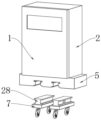
Referring to fig. 1, 3-9, a control box convenient to operate comprises a box door 1, a box body 2 and a hinge 3, wherein one side of the box door 1 is connected with one side of the box body 2 through the hinge 3, a fixed base 5 is fixed at the bottom of the box body 2, and a lifting mechanism for adjusting the height is arranged at the bottom of the fixed base 5;
the lifting mechanism comprises a first fixed block 6, a fixed plate 16, a first connecting plate 17, a first connecting rod 18, a second connecting rod 19, a second connecting plate 20, a transmission base 21 and a driving shaft 27, wherein one side of the first connecting rod 18 is rotationally connected with the second connecting rod 19, the first connecting rod 18 and the second connecting rod 19 are rotationally connected through the middle part, the first connecting rod 18 and the second connecting rod 19 can be relatively rotated by taking the rotational connection of the rotation as the center of a circle, one end of the first connecting rod 18 is rotationally connected with the first connecting plate 17, the top of the first connecting plate 17 is fixedly provided with the fixed plate 16, both ends of the top of the fixed plate 16 are fixedly provided with the first fixed block 6, the first fixed block 6 is in sliding connection with the fixed base 5, the first fixed block 6 can be conveniently arranged in the fixed base 5, the first fixed block 6 can only be separated from the fixed base 5 through the entering direction, one end of the second connecting rod 19 is rotationally connected with the second connecting plate 20, the bottom of the second connecting rod 20 is fixedly provided with the transmission base 21, the other ends of the first connecting rod 18 and the second connecting rod 19 are rotationally connected with the driving shaft 27, one of the other ends is in the sliding connection 27 with the first connecting plate 20, and the other driving shaft 27 is in sliding connection with the first connecting plate 20;
the inside of the transmission base 21 is also provided with a transmission assembly for driving the driving shaft 27 to move, the transmission assembly comprises a second motor 22, a first bevel gear 23, a second bevel gear 24, a transmission shaft 25 and a third connecting plate 26, the inside of the transmission base 21 is rotationally connected with the transmission shaft 25, a threaded section is arranged on the outer side of one end of the transmission shaft 25, the outer side of the threaded section is in threaded connection with the third connecting plate 26, the third connecting plate 26 is in sliding connection with the transmission base 21, the third connecting plate 26 can be driven to move on the inner side of the transmission base 21 by rotation of the threaded section, the top of the third connecting plate 26 is fixed with the other driving shaft 27, and therefore the other driving shaft 27 is driven to move by movement of the third connecting plate 26;
the inside of the transmission base 21 is also fixed with a second motor 22, the output end of the second motor 22 is connected with a first bevel gear 23, the top end of the first bevel gear 23 is connected with a second bevel gear 24 in a meshed manner, and the second bevel gear 24 is fixed on the outer side of a transmission shaft 25, so that the transmission shaft 25 can be driven to rotate by the rotation of the second bevel gear 24;
the positioning mechanism for limiting is arranged in the fixed base 5, the positioning mechanism comprises a guide rod 8, a guide block 9, a positioning shell 10, racks 11, a first motor 12, a transmission gear 13, a buckle 14 and a reset spring 15, the bottom of the first motor 12 is fixed with the fixed base 5, the output end of the first motor 12 is connected with the transmission gear 13, the racks 11 are engaged and connected on two sides of the transmission gear 13, so that the two racks 11 are driven to reversely move through the rotation of the transmission gear 13, the guide block 9 is fixed at one end, far away from the transmission gear 13, of the racks 11, the guide rods 8 are connected inside the two ends of the guide block 9 in a sliding mode, and the guide rods 8 are fixed with the fixed base 5, so that the guide block 9 can move more stably through the sliding connection of the guide rods 8 and the guide blocks 9;
the bottom of the guide block 9 is fixedly provided with a positioning shell 10, the inside of one end of the positioning shell 10 is slidably connected with a buckle 14, the two buckles 14 are positioned at the adjacent ends of the two positioning shells 10, the buckle 14 and the fixed base 5 are slidably connected, the buckle 14 and the first fixed block 6 are slidably connected, one end of the buckle 14 is provided with an inclined surface, so that the first fixed block 6 can be extruded by facing the buckle 14 through the inclined surface when being slidably connected into the fixed base 5, the inside of the positioning shell 10 is fixedly provided with a reset spring 15 at one end of the buckle 14, and the movement of the buckle 14 is reset through the compression and rebound of the reset spring 15;
preferably, the inclined surface is arc-shaped or straight.
Examples
Referring to fig. 1 to 2, in a first difference from the embodiment, there is:
the bottom of unable adjustment base 5 is installed and is used for carrying out the removal subassembly of displacement, the removal subassembly includes wheel 4, first linkage piece 7 and second fixed block 28, the top of first linkage piece 7 is fixed with second fixed block 28, and second fixed block 28 and buckle 14 sliding connection, make the removal of buckle 14 can get into the inside of second fixed block 28 through unable adjustment base 5, between second fixed block 28 and the unable adjustment base 5, equal sliding connection between second fixed block 28 and the buckle 14, thereby can let the inboard of the more convenient assembly of second fixed block 28 in unable adjustment base 5 bottom, and carry out the position fixing to the second fixed block 28 that gets into unable adjustment base 5 inside through positioning mechanism, and let second fixed block 28 break away from unable adjustment base 5 through the direction of getting into, the bottom of first linkage piece 7 is provided with wheel 4, thereby can be adjusted the position of box 2 through the contact of wheel 4 and ground.
From the above, it can be seen that:
the utility model aims at the technical problems that: the existing control box is inconvenient to adjust the height according to the needs when in use; the technical scheme of each embodiment is adopted. Meanwhile, the implementation process of the technical scheme is as follows:
when the box body 2 needs to move, the second fixing block 28 is installed on the inner side of the fixing base 5 through sliding connection, then the inclined surface on the buckle 14 is extruded through movement after the second fixing block 28 enters the inner side of the fixing base 5, the buckle 14 is extruded through the shape of the inclined surface and then enters the inside of the positioning shell 10 and extrudes the return spring 15, when the second fixing block 28 moves to a proper position, the extrusion external force born by the buckle 14 disappears, the buckle 14 slides into the inside of the second fixing block 28 through rebound after the compression of the return spring 15, so that the position of the second fixing block 28 is positioned, the second fixing block 28 can only be separated from the fixing base 5 through the entering direction, and then the position of the box body 2 is adjusted through the contact between the bottom of the wheel 4 and the ground;
when the box body 2 moves to a proper position and needs to be installed and fixed, the transmission base 21 is fixed with the ground, the sliding connection between the fixed base 5 and the first fixed block 6 at the bottom of the box body 2 is installed at the inner side of the fixed base 5, meanwhile, the third connecting plate 26 can only be separated from the fixed base 5 through the entering direction, and the first fixed block 6 entering the fixed base 5 is fixed through the movement of the buckle 14;
the second motor 22 is electrically connected with an external power supply, the second motor 22 drives the first bevel gear 23 to rotate, the rotation of the first bevel gear 23 drives the second bevel gear 24 to rotate, the rotation of the second bevel gear 24 drives the threaded section to rotate through the transmission shaft 25, the rotation of the threaded section drives the third connecting plate 26 in threaded connection to move, the movement of the third connecting plate 26 drives the driving shaft 27 inside the first connecting rod 18 to move, the driving shaft 27 inside the first connecting rod 18 slides on the inner side of the second connecting plate 20, the sliding of the driving shaft 27 inside the first connecting rod 18 drives the first connecting rod 18 to move, and the first connecting rod 18 and the second connecting rod 19 and one end of the second connecting rod 19 connected with the second connecting rod 20 are gradually close to each other, the fixing plate 16 is lifted through the rotating connection of the first connecting rod 18 and the first connecting rod 17 and the sliding connection of the driving shaft 27 inside the second connecting rod 19 and the first connecting rod 17, and the fixing plate 16 is lifted through the first fixing block 6;
when the first fixed block 6 or the second fixed block 28 is required to be taken out and separated from the fixed base 5, the transmission gear 13 is driven to rotate through the first motor 12 and the external power supply, the rotation of the transmission gear 13 drives the two racks 11 to move reversely, the movement of the racks 11 drives the guide block 9 to move, the movement of the guide block 9 drives the positioning shell 10 to move, the positioning shell 10 drives the buckle 14 to move, the buckle 14 is separated from the first fixed block 6 or the second fixed block 28 in sliding connection, and the fixed base 5 is separated from the first fixed block 6 or the second fixed block 28.
Through above-mentioned setting, this application must solve above-mentioned technical problem, simultaneously, realizes following technical effect:
through unable adjustment base 5, elevating system, the cooperation of first fixed block 6 and positioning mechanism for the control box can be convenient for carry out the altitude mixture control as required when using, and can let unable adjustment base 5 and first fixed block 6 fixed more firm according to positioning mechanism.
Through the cooperation of wheel 4, unable adjustment base 5, first fixed block 6, first connecting block 7 and location structure for the switch board can be convenient for more remove when using, thereby can adjust the position of switch board.
The foregoing has shown and described the basic principles, principal features and advantages of the utility model. It will be understood by those skilled in the art that the present utility model is not limited to the embodiments described above, and that the above embodiments and descriptions are merely illustrative of the principles of the present utility model, and various changes and modifications may be made therein without departing from the spirit and scope of the utility model, which is defined by the appended claims. The scope of the utility model is defined by the appended claims and equivalents thereof.
Claims (7)
1. The control box convenient to operate comprises a box door (1), a box body (2) and a hinge (3), wherein one side of the box door (1) is connected with one side of the box body (2) through the hinge (3), the control box is characterized in that a fixed base (5) is fixed at the bottom of the box body (2),
the utility model discloses a fixing base, including fixed base (5), internally mounted has the positioning mechanism who is used for carrying out spacing, positioning mechanism includes positioning shell (10), buckle (14) and reset spring (15), the inside sliding connection of positioning shell (10) one end has buckle (14), the inclined plane has been seted up to the one end of buckle (14), the inside of positioning shell (10) just is located the one end of buckle (14) and is fixed with reset spring (15).
2. The control box convenient to operate according to claim 1, wherein the positioning mechanism comprises a guide block (9), a rack (11), a first motor (12) and a transmission gear (13), the bottom of the first motor (12) is fixed with the fixed base (5), the output end of the first motor (12) is connected with the transmission gear (13), two sides of the transmission gear (13) are connected with the rack (11) in a meshed mode, one end, far away from the transmission gear (13), of the rack (11) is fixed with the guide block (9), and the bottom of the guide block (9) is fixed with the positioning shell (10).
3. The control box convenient to operate according to claim 1, wherein a lifting mechanism for height adjustment is installed at the bottom of the fixed base (5), the lifting mechanism comprises a first fixed block (6), a fixed plate (16), a first connecting plate (17), a first connecting rod (18) and a second connecting rod (19), one side of the first connecting rod (18) is rotationally connected with the second connecting rod (19), one end of the first connecting rod (18) is rotationally connected with the first connecting plate (17), the top of the first connecting plate (17) is fixed with the fixed plate (16), the two ends of the top of the fixed plate (16) are both fixed with the first fixed block (6), and the first fixed block (6) is in sliding connection with the fixed base (5).
4. A control box convenient to operate according to claim 3, characterized in that the lifting mechanism comprises a second connecting plate (20), a transmission base (21) and a driving shaft (27), one end of the second connecting rod (19) is rotatably connected with the second connecting plate (20), the transmission base (21) is fixed at the bottom of the second connecting plate (20), the driving shaft (27) is rotatably connected with the inside of the other end of the first connecting rod (18) and the second connecting rod (19), and one of the driving shafts (27) is slidably connected with the first connecting plate (17), and the other driving shaft (27) is slidably connected with the second connecting plate (20).
5. The control box convenient to operate according to claim 4, wherein a transmission assembly for driving a driving shaft (27) to move is further installed in the transmission base (21), the transmission assembly comprises a second motor (22), a first bevel gear (23), a second bevel gear (24), a transmission shaft (25) and a third connecting plate (26), the transmission base (21) is internally and rotatably connected with the transmission shaft (25), a threaded section is formed on the outer side of one end of the transmission shaft (25), a third connecting plate (26) is connected on the outer side of the threaded section in a threaded manner, the third connecting plate (26) is in sliding connection with the transmission base (21), and the top of the third connecting plate (26) is fixed with the other driving shaft (27);
the inside of transmission base (21) still is fixed with second motor (22), the output of second motor (22) is connected with first bevel gear (23), the top meshing of first bevel gear (23) is connected with second bevel gear (24), just second bevel gear (24) are fixed in the outside of transmission shaft (25).
6. The control box convenient to operate according to claim 2, wherein the inside of both ends of the guide block (9) is slidably connected with a guide rod (8), and the guide rod (8) is fixed with the fixed base (5).
7. The control box convenient to operate according to claim 1, characterized in that a moving assembly for carrying out displacement is installed at the bottom of the fixed base (5), the moving assembly comprises wheels (4), a first connecting block (7) and a second fixed block (28), the second fixed block (28) is fixed at the top of the first connecting block (7), sliding connection is carried out between the second fixed block (28) and the fixed base (5) and between the second fixed block (28) and the buckle (14), and the wheels (4) are arranged at the bottom of the first connecting block (7).
Priority Applications (1)
| Application Number | Priority Date | Filing Date | Title |
|---|---|---|---|
| CN202223223424.3U CN219097428U (en) | 2022-12-02 | 2022-12-02 | Control box convenient to operate |
Applications Claiming Priority (1)
| Application Number | Priority Date | Filing Date | Title |
|---|---|---|---|
| CN202223223424.3U CN219097428U (en) | 2022-12-02 | 2022-12-02 | Control box convenient to operate |
Publications (1)
| Publication Number | Publication Date |
|---|---|
| CN219097428U true CN219097428U (en) | 2023-05-30 |
Family
ID=86467017
Family Applications (1)
| Application Number | Title | Priority Date | Filing Date |
|---|---|---|---|
| CN202223223424.3U Active CN219097428U (en) | 2022-12-02 | 2022-12-02 | Control box convenient to operate |
Country Status (1)
| Country | Link |
|---|---|
| CN (1) | CN219097428U (en) |
-
2022
- 2022-12-02 CN CN202223223424.3U patent/CN219097428U/en active Active
Similar Documents
| Publication | Publication Date | Title |
|---|---|---|
| CN219097428U (en) | Control box convenient to operate | |
| CN201411980Y (en) | Door or window lock | |
| CN113339646B (en) | Energy-conserving building air source heat pump base | |
| CN216789924U (en) | Searchlighting device for small-clear-distance tunnel construction | |
| CN112493738B (en) | Wave-type chair pillow adjusting mechanism | |
| CN111332589B (en) | A first aid device that is used for outdoor proruption incident medical treatment first aid to use | |
| CN211148899U (en) | Installation base structure of radar equipment | |
| CN211008121U (en) | Electric pulley device and sliding door with same | |
| CN215436798U (en) | Motor housing with adjustable base | |
| CN219584083U (en) | Car machine display screen device capable of freely adjusting angle | |
| CN214284017U (en) | Cabinet door lifting mechanism of intelligent bed cabinet | |
| CN220453338U (en) | Building is monitoring device for security protection | |
| CN220923947U (en) | Folding bed for caravan | |
| CN210319255U (en) | Air energy pump convenient to move | |
| CN215385293U (en) | High-protection electric shifter | |
| CN215891726U (en) | Personnel management is with intelligent entrance guard that can realize diversified control | |
| CN214896964U (en) | Lifting type mobile signal lamp | |
| CN219497111U (en) | Intelligent security device for building | |
| CN219795026U (en) | Electric stay bar | |
| CN212350865U (en) | Portable bridge steel structure welding set of protection against electric shock | |
| CN217635165U (en) | Adjustable building energy-saving illuminating lamp | |
| CN215485034U (en) | Non-stay wire corner rod convenient to climb and maintain | |
| CN220433811U (en) | Electrodeless adjusting device for converting load into self-locking force | |
| CN215225821U (en) | Wisdom filing cabinet based on human-computer interaction | |
| CN218094563U (en) | Linear stroke mechanism of actuator |
Legal Events
| Date | Code | Title | Description |
|---|---|---|---|
| GR01 | Patent grant | ||
| GR01 | Patent grant |