CN219093273U - Bending device for engine compartment wire harness bracket - Google Patents
Bending device for engine compartment wire harness bracket Download PDFInfo
- Publication number
- CN219093273U CN219093273U CN202320164295.0U CN202320164295U CN219093273U CN 219093273 U CN219093273 U CN 219093273U CN 202320164295 U CN202320164295 U CN 202320164295U CN 219093273 U CN219093273 U CN 219093273U
- Authority
- CN
- China
- Prior art keywords
- bending
- engine compartment
- wire harness
- sets
- positioning
- Prior art date
- Legal status (The legal status is an assumption and is not a legal conclusion. Google has not performed a legal analysis and makes no representation as to the accuracy of the status listed.)
- Active
Links
Images


Classifications
-
- Y—GENERAL TAGGING OF NEW TECHNOLOGICAL DEVELOPMENTS; GENERAL TAGGING OF CROSS-SECTIONAL TECHNOLOGIES SPANNING OVER SEVERAL SECTIONS OF THE IPC; TECHNICAL SUBJECTS COVERED BY FORMER USPC CROSS-REFERENCE ART COLLECTIONS [XRACs] AND DIGESTS
- Y02—TECHNOLOGIES OR APPLICATIONS FOR MITIGATION OR ADAPTATION AGAINST CLIMATE CHANGE
- Y02T—CLIMATE CHANGE MITIGATION TECHNOLOGIES RELATED TO TRANSPORTATION
- Y02T10/00—Road transport of goods or passengers
- Y02T10/10—Internal combustion engine [ICE] based vehicles
- Y02T10/40—Engine management systems
Abstract
The utility model relates to the technical field of automobile part machining, in particular to a bending device for an engine compartment wire harness bracket, which comprises a machining table, a pressing plate arranged in a rack and a hydraulic cylinder arranged at the inner top of the rack, wherein a detachable die structure is arranged in the middle of the upper side surface of the machining table, and a pressure head structure is arranged in the middle of the surface of one side of the pressing plate; the detachable die structure comprises a bending die, the bending die is arranged in a mounting groove, a dovetail sliding block is arranged on one side surface of the bending die, one end of the dovetail sliding block is clamped in a dovetail sliding groove, a metal positioning block is arranged on one side surface of the bending die, one end of the metal positioning block is arranged in a positioning groove, the positioning groove is arranged on one side surface in the mounting groove, and an electromagnet is arranged on one side surface in the positioning groove.
Description
Technical Field
The utility model relates to the technical field of automobile part machining, in particular to a bending device for an engine compartment wire harness bracket.
Background
In the production process of the engine compartment wire harness bracket, a bending device is required to bend the engine compartment wire harness bracket.
The utility model discloses a bending device for an engine compartment wire harness bracket, which comprises a base, wherein stand columns are arranged on two sides of the upper end of the base, a mounting plate is arranged between the top ends of the two stand columns, a hydraulic cylinder is arranged in the middle of the upper end of the mounting plate, a lifting plate is connected to a piston rod of the hydraulic cylinder, a punching block is arranged in the middle of the lower end of the lifting plate, first grooves are formed in two sides of the lower end of the punching block, punching plates are hinged to the side walls of the lower end of the first grooves, second grooves are formed in two sides of the upper end of the punching block, electric telescopic rods are arranged in the second grooves, the other ends of the electric telescopic rods are hinged to the top ends of the punching plates, a plurality of pressing devices are uniformly distributed around the punching block on the lifting plate, an air cooler is arranged at the upper end of the lifting plate close to a piston rod, an air outlet of the air cooler is communicated with the second pipeline arranged in the lifting plate through the first pipeline, a plurality of third pipelines penetrating through the lower end of the mounting plate are arranged on the lower side of the second pipeline, grooves are formed in the upper surface of the base, corresponding to the lower part of the punching block, the punching block cannot be replaced by the punching block and a punching die, the upper surface of the punching plate is not convenient to bend wire harness bracket, and the wire harness bracket is not convenient to bend and limited to be used.
Disclosure of Invention
In order to solve the technical problems in the background art, the utility model provides a bending device for an engine compartment wire harness bracket, which comprises a processing table, a rack arranged on the upper side surface of the processing table, a pressing plate arranged in the rack and a hydraulic cylinder arranged at the inner top of the rack, wherein one end of the hydraulic cylinder is connected with the pressing plate, a detachable die structure is arranged in the middle of the upper side surface of the processing table, and a pressing head structure is arranged in the middle of the surface of one side of the pressing plate;
the detachable die structure comprises a bending die, the bending die is arranged in a mounting groove, the mounting groove is formed in the middle of the upper side surface of the processing table, a dovetail sliding block is arranged on one side surface of the bending die, one end of the dovetail sliding block is clamped in a dovetail sliding groove, the dovetail sliding groove is arranged on one side surface in the mounting groove, a metal positioning block is arranged on one side surface of the bending die, one end of the metal positioning block is arranged in a positioning groove, the positioning groove is formed in one side surface in the mounting groove, and an electromagnet is arranged on one side surface in the positioning groove.
Preferably, the electromagnet is in adsorption connection with the metal positioning block, the electromagnet is electrically connected with the control panel through a connecting wire, and the control panel is arranged on one side surface of the frame.
Preferably, the fixing plates are symmetrically arranged on one side surface of the bending die and fixedly connected with the processing table through the first locking bolts.
Preferably, the pressure head structure comprises a mounting seat, the mounting seat is arranged in the middle of the lower side face of the pressing plate, a bending pressure head is arranged on the lower side face of the mounting seat, a connector is arranged on one side surface of the bending pressure head and in the groove, and the connector is fixedly connected with the mounting seat through a second locking bolt.
Preferably, the positioning guide structures are symmetrically arranged on the surfaces of two sides of the pressing plate, the positioning guide structures comprise positioning plates, the positioning plates are arranged at one ends of the adjusting rods, the adjusting rods are movably arranged in adjusting holes, the adjusting holes are formed in one side of the pressing plate, reset springs are symmetrically arranged on the two sides of the upper surface of the positioning plates, and one ends of the reset springs are fixedly connected with the pressing plate.
Preferably, a groove body is arranged on one side surface of the positioning plate, and guide rotating rollers are arranged in the groove body in an equidistant rotation mode.
Preferably, a limiting disc is arranged on the other side of the adjusting rod, and the diameter size of the limiting disc is larger than that of the adjusting hole.
Compared with the prior art, the technical scheme provided by the utility model has the following beneficial technical effects:
the bending die and the bending press head can be replaced, the bending requirements of different bending shapes of the wire harness bracket can be met, the bending range is enlarged, and the machining flexibility is improved.
Drawings
Fig. 1 is a schematic structural view of a bending device for an engine compartment wire harness bracket according to a first embodiment;
FIG. 2 is a schematic right side cross-sectional view of a detachable mold structure in a bending device for an engine compartment wire harness bracket;
FIG. 3 is a schematic view of a partial enlarged structure at A in FIG. 1;
FIG. 4 is a schematic view of a cross-sectional front view of a ram structure in a bending device for an engine compartment wire harness bracket;
fig. 5 is a schematic view showing a cross-sectional front view of a positioning guide structure in a bending device for an engine compartment wire harness bracket.
Reference numerals: 1. a detachable mold structure; 2. a pressure head structure; 3. positioning and guiding structure; 4. a frame; 5. a hydraulic cylinder; 6. a control panel; 7. a processing table; 8. a pressing plate; 11. bending a die; 12. a positioning groove; 13. an electromagnet; 14. a metal positioning block; 15. dovetail slide blocks; 16. dovetail grooves; 17. a fixing plate; 18. a first locking bolt; 21. a mounting base; 22. a connector; 23. a second locking bolt; 24. bending press heads; 25. a groove; 31. a positioning plate; 32. a return spring; 33. a limiting disc; 34. an adjusting rod; 35. a tank body; 36. and guiding the rotating roller.
Detailed Description
Example 1
As shown in fig. 1-3, the bending device for the engine compartment wire harness bracket provided by the utility model comprises a processing table 7, a frame 4 arranged on the upper side surface of the processing table 7, a pressing plate 8 arranged in the frame 4 and a hydraulic cylinder 5 arranged at the top in the frame 4, wherein one end of the hydraulic cylinder 5 is connected with the pressing plate 8, a detachable die structure 1 is arranged in the middle of the upper side surface of the processing table 7, and a pressing head structure 2 is arranged in the middle of the surface of one side of the pressing plate 8;
the detachable die structure 1 comprises a bending die 11, the bending die 11 is arranged in a mounting groove, the mounting groove is arranged in the middle of the upper side surface of the processing table 7, a dovetail sliding block 15 is arranged on one side surface of the bending die 11, one end of the dovetail sliding block 15 is clamped in a dovetail sliding groove 16, the dovetail sliding groove 16 is arranged on one side surface in the mounting groove, a metal positioning block 14 is arranged on one side surface of the bending die 11, one end of the metal positioning block 14 is arranged in a positioning groove 12, the positioning groove 12 is arranged on one side surface in the mounting groove, and an electromagnet 13 is arranged on one side surface in the positioning groove 12.
In this embodiment, according to the shape of bending, install corresponding bending mould 11 in the mounting groove, go into dovetail slide 16 with the block of dovetail slider 15 card, and promote bending mould 11, bending mould 11 drives the cigarette taste slider and removes in dovetail slide 16, bending mould 11 drives metal locating piece 14 simultaneously and removes, when dovetail slide 15 card goes into dovetail slide 16 completely, metal locating piece 14 card goes into the constant head tank 12, adsorb fixed with metal locating piece 14 through electro-magnet 13, accomplish the installation of bending mould 11, then place engine compartment pencil support on processing platform 7, drive clamp plate 8 through pneumatic cylinder 5 and remove, clamp plate 8 drives pressure head structure 2 and removes, bend engine compartment pencil support through the pressure head.
The electromagnet 13 is in adsorption connection with the metal positioning block 14, the electromagnet 13 is electrically connected with the control panel 6 through a connecting wire, and the control panel 6 is arranged on one side surface of the frame 4 and can control the electromagnet 13.
The fixing plate 17 is symmetrically arranged on one side surface of the bending die 11, and the fixing plate 17 is fixedly connected with the processing table 7 through the first locking bolt 18, so that the firmness of the bending die 11 during installation can be further improved.
Example two
As shown in fig. 4, compared with the first embodiment, the bending device for the engine compartment wire harness bracket provided by the utility model further comprises a press head structure 2, wherein the press head structure 2 comprises a mounting seat 21, the mounting seat 21 is arranged in the middle of the lower side surface of the press plate 8, a bending press head 24 is arranged on the lower side surface of the mounting seat 21, a connector 22 is arranged on one side surface of the bending press head 24, the connector 22 is arranged in a groove 25, and the connector 22 is fixedly connected with the mounting seat 21 through a second locking bolt 23.
In this embodiment, the connector 22 on the bending press head 24 with a corresponding shape is inserted into the groove 25, the connector 22 is fixed by the second locking bolt 23, the bending press head 24 is mounted on the mounting seat 21, and the bending operation is performed on the engine compartment wire harness bracket by the bending press head 24.
Example III
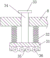
As shown in fig. 5, compared with the first embodiment or the second embodiment, the bending device for the engine compartment wire harness bracket provided by the utility model further comprises a positioning guide structure 3, wherein the positioning guide structure 3 is symmetrically arranged on two side surfaces of the pressing plate 8, the positioning guide structure 3 comprises a positioning plate 31, the positioning plate 31 is arranged at one end of an adjusting rod 34, the adjusting rod 34 is movably arranged in an adjusting hole, the adjusting hole is arranged at one side of the pressing plate 8, two sides of the upper surface of the positioning plate 31 are symmetrically provided with reset springs 32, one end of each reset spring 32 is fixedly connected with the pressing plate 8, a groove body 35 is arranged on one side surface of the positioning plate 31, and guide rotating rollers 36 are equidistantly arranged in the groove body 35 in a rotating manner.
In this embodiment, when the pressing plate 8 moves downward, the pressing plate 8 drives the positioning plate 31 to move downward, the positioning plate 31 drives the guiding roller 36 to move downward, after the guiding roller 36 is attached to the engine compartment wire harness support, the positioning plate 31 drives the adjusting rod 34 to move, the positioning plate 31 compresses the return spring 32, the return spring 32 enables the guiding roller 36 to attach to the engine compartment wire harness support under the action of elasticity, and when the bending press head 24 bends, the two ends of the engine compartment wire harness support drive the guiding roller 36 to rotate, so as to guide the engine compartment wire harness support.
The limiting disc 33 is arranged on the other side of the adjusting rod 34, and the diameter size of the limiting disc 33 is larger than that of the adjusting hole, so that the adjusting rod 34 is convenient to limit.
The embodiments of the present utility model have been described in detail with reference to the drawings, but the present utility model is not limited thereto, and various changes can be made within the knowledge of those skilled in the art without departing from the spirit of the present utility model.
Claims (7)
1. The utility model provides a bending device for engine compartment pencil support, includes processing platform (7), sets up frame (4) on the side on processing platform (7), sets up clamp plate (8) in frame (4) and sets up pneumatic cylinder (5) at the top in frame (4), pneumatic cylinder (5) one end is connected with clamp plate (8), its characterized in that, processing platform (7) upper side middle part sets up dismantlement formula mould structure (1), clamp plate (8) one side surface middle part sets up pressure head structure (2);
the utility model provides a dismantlement formula mould structure (1) is including bending mould (11), bending mould (11) set up in the mounting groove, the mounting groove sets up in the middle part of the side on processing platform (7), bending mould (11) one side surface sets up forked tail slider (15), forked tail slider (15) one end joint is in forked tail spout (16), forked tail spout (16) set up one side surface in the mounting groove, bending mould (11) one side surface sets up metal locating piece (14), metal locating piece (14) one end sets up in constant head tank (12), constant head tank (12) set up one side surface in the mounting groove, one side surface sets up electro-magnet (13) in constant head tank (12).
2. The bending device for the engine compartment wire harness bracket according to claim 1, wherein the electromagnet (13) is in adsorption connection with the metal positioning block (14), the electromagnet (13) is electrically connected with the control panel (6) through a connecting wire, and the control panel (6) is arranged on one side surface of the frame (4).
3. The bending device for the engine compartment wire harness bracket according to claim 1, wherein a fixing plate (17) is symmetrically arranged on one side surface of the bending die (11), and the fixing plate (17) is fixedly connected with the processing table (7) through a first locking bolt (18).
4. The bending device for the engine compartment wire harness bracket according to claim 1, wherein the pressure head structure (2) comprises a mounting seat (21), the mounting seat (21) is arranged in the middle of the lower side surface of the pressure plate (8), a bending pressure head (24) is arranged on the lower side surface of the mounting seat (21), a connector (22) is arranged on one side surface of the bending pressure head (24), the connector (22) is arranged in the groove (25), and the connector (22) is fixedly connected with the mounting seat (21) through a second locking bolt (23).
5. The bending device for the engine compartment wire harness bracket according to claim 1, wherein positioning guide structures (3) are symmetrically arranged on two side surfaces of the pressing plate (8), the positioning guide structures (3) comprise positioning plates (31), the positioning plates (31) are arranged at one ends of adjusting rods (34), the adjusting rods (34) are movably arranged in adjusting holes, the adjusting holes are formed in one side of the pressing plate (8), return springs (32) are symmetrically arranged on two sides of the upper surface of the positioning plates (31), and one ends of the return springs (32) are fixedly connected with the pressing plate (8).
6. The bending device for the engine compartment wire harness bracket according to claim 5, wherein a groove body (35) is formed in one side surface of the positioning plate (31), and guide rotating rollers (36) are arranged in the groove body (35) in an equidistant rotation mode.
7. The bending device for the engine compartment wire harness bracket according to claim 5, wherein a limiting disc (33) is arranged on the other side of the adjusting rod (34), and the diameter size of the limiting disc (33) is larger than that of the adjusting hole.
Priority Applications (1)
| Application Number | Priority Date | Filing Date | Title |
|---|---|---|---|
| CN202320164295.0U CN219093273U (en) | 2023-02-09 | 2023-02-09 | Bending device for engine compartment wire harness bracket |
Applications Claiming Priority (1)
| Application Number | Priority Date | Filing Date | Title |
|---|---|---|---|
| CN202320164295.0U CN219093273U (en) | 2023-02-09 | 2023-02-09 | Bending device for engine compartment wire harness bracket |
Publications (1)
| Publication Number | Publication Date |
|---|---|
| CN219093273U true CN219093273U (en) | 2023-05-30 |
Family
ID=86466001
Family Applications (1)
| Application Number | Title | Priority Date | Filing Date |
|---|---|---|---|
| CN202320164295.0U Active CN219093273U (en) | 2023-02-09 | 2023-02-09 | Bending device for engine compartment wire harness bracket |
Country Status (1)
| Country | Link |
|---|---|
| CN (1) | CN219093273U (en) |
-
2023
- 2023-02-09 CN CN202320164295.0U patent/CN219093273U/en active Active
Similar Documents
| Publication | Publication Date | Title |
|---|---|---|
| CN201012426Y (en) | Butt welding machine | |
| CN112517767A (en) | Composite die device | |
| CN207887776U (en) | A kind of anchor ear one-shot forming apparatus | |
| CN210790734U (en) | Tool for assembling gear parts | |
| CN108284165B (en) | Flaring mechanism and tube expander with same | |
| CN219093273U (en) | Bending device for engine compartment wire harness bracket | |
| CN110523823B (en) | Bending processing equipment for Z-shaped structure metal plate | |
| CN210450526U (en) | Pipe wall punching equipment | |
| CN111496022A (en) | Small-sized metal component continuous bending device and implementation method | |
| CN111167894A (en) | High stability hydraulic pressure sheet material bender | |
| CN208245674U (en) | A kind of fixed device of stamping die processing | |
| CN210253689U (en) | Leaf spring frock of bending | |
| CN115106750A (en) | Automatic assembly mechanism for screw rod bearing and bearing seat | |
| CN104668325A (en) | Novel press machine | |
| CN211218174U (en) | Bending device for engine compartment wire harness support | |
| CN210231220U (en) | Unilateral bending die | |
| CN210586526U (en) | Push-down structure and upward-moving bending machine applying same | |
| CN218136163U (en) | Automatic assembly mechanism for screw rod bearing and bearing seat | |
| CN215318206U (en) | Automobile parts frame processing frock | |
| CN217700802U (en) | Multi-station bending machine | |
| CN218136162U (en) | Automatic assembly mechanism for screw rod bearing block | |
| CN214813830U (en) | Automatic bending, forming and pressing equipment for refrigerator door shell plate | |
| CN217315435U (en) | Automatic transfer die | |
| CN219944217U (en) | Bending device for steel processing | |
| CN204912500U (en) | Truck frame cross longeron one shot forming resilience controlling means |
Legal Events
| Date | Code | Title | Description |
|---|---|---|---|
| GR01 | Patent grant | ||
| GR01 | Patent grant |