CN219078841U - Quick hoist device of PC component - Google Patents
Quick hoist device of PC component Download PDFInfo
- Publication number
- CN219078841U CN219078841U CN202320089624.XU CN202320089624U CN219078841U CN 219078841 U CN219078841 U CN 219078841U CN 202320089624 U CN202320089624 U CN 202320089624U CN 219078841 U CN219078841 U CN 219078841U
- Authority
- CN
- China
- Prior art keywords
- component
- clamping
- rod
- adjustment mechanism
- sliding
- Prior art date
- Legal status (The legal status is an assumption and is not a legal conclusion. Google has not performed a legal analysis and makes no representation as to the accuracy of the status listed.)
- Active
Links
Images


Abstract
The utility model provides a PC component quick lifting device which comprises a lifting device body, wherein the lifting device body comprises a clamping assembly, a steel rope, a longitudinal adjusting mechanism and a transverse adjusting mechanism, a sliding sleeve is arranged at the top of the longitudinal adjusting mechanism, a lifting ring is arranged at the top of the sliding sleeve, the bottom end of the steel rope is fixedly connected with the longitudinal adjusting mechanism through the lifting ring, the transverse adjusting mechanism is inserted into the longitudinal adjusting mechanism, a pull rod is arranged at the tail end of the longitudinal adjusting mechanism, and the PC component quick lifting device can control the specific point of clamping connection between the clamping assembly at the bottom and the edge of the PC component through controlling the longitudinal adjusting mechanism and the transverse adjusting mechanism, so that the clamping firmness is improved according to specific size and specification of the component, the shaking amplitude in the lifting process of the component can be reduced in the subsequent lifting process, and the safety is improved.
Description
Technical Field
The utility model relates to the technical field of building construction, in particular to a PC component quick hoisting device.
Background
PC component refers to the precast concrete component, and its wide application is in various building construction places, can realize constructing the effect fast, need use hoisting device to carry and remove the PC component in the construction process. According to the technical scheme disclosed in the prior art, according to the concrete prefabricated part lifting device disclosed in the Chinese patent document CN202021291773.7, the clamping plates are positioned at the bottom of the concrete prefabricated part through the manual movable clamping plates, then the cross locking pins are used for inserting the clamping plates, so that the clamping plates are fixed.
According to the technical scheme disclosed by the technical scheme, the edge of the PC component is supported in the prior art, but the PC components with different sizes are required to be used for corresponding clamp types, so that the application range of the hoisting device with the same size is limited, on the other hand, a steel rope is required to be used for hoisting during hoisting, and if the gravity center of the PC component is deviated after clamping, the whole component is easy to incline, so that the risk of the hoisting process is increased.
Disclosure of Invention
Aiming at the defects existing in the prior art, the utility model aims to provide a quick lifting device for PC components, so as to solve the problems in the prior art.
In order to achieve the above object, the present utility model is realized by the following technical scheme: the utility model provides a quick hoist device of PC component, includes the hoist device body, the hoist device body includes clamping subassembly, cable wire, vertical adjustment mechanism and transverse adjustment mechanism, vertical adjustment mechanism's top is provided with the slip sleeve, rings are installed at the slip telescopic top, the bottom of cable wire is through this rings and vertical adjustment mechanism part fixed connection, transverse adjustment mechanism alternates the inside to vertical adjustment mechanism, the pull rod is installed to vertical adjustment mechanism's end, every independent clamping subassembly is all installed to the bottom of pull rod.
Further, the vertical adjustment mechanism includes slide bar and sliding frame, sliding sleeve is provided with at sliding frame's top, the slide bar passes from sliding sleeve's inside, sliding frame's inside is provided with the flexible passageway, the inside of flexible passageway is inserted to horizontal adjustment mechanism's one end.
Further, an adjusting through hole is formed in the top of the sliding frame, the two sliding sleeves are connected through a threaded rod, and a hand wheel is mounted at one end of the threaded rod.
Further, limiting plate structures are arranged at two ends of the sliding rod, two ends of the threaded rod are embedded into the outer side of the sliding sleeve through bearings, and two groups of transverse adjusting mechanisms with opposite directions are inserted into the longitudinal adjusting mechanisms.
Further, the transverse adjusting mechanism comprises an extension rod, a rack and a linkage gear, wherein the rack is arranged on one side of the extension rod, a rotating shaft is arranged at one end of the extension rod, and a clamping assembly is arranged at the bottom of the rotating shaft.
Further, the screw thread sleeve is installed at the top of one of the extension bars in the sliding frame, the screw thread sleeve outwards penetrates out from the inside of the adjusting through hole, the screw thread sleeve is sleeved on the surface of the threaded rod, the linkage gear is installed in the middle of the sliding frame, and the linkage gear and racks on two sides are meshed with each other.
Further, the clamping assembly comprises a pull rod and springs, butt joint plates are arranged at two ends of the rotating shaft, fixing bayonet locks are inserted in the butt joint plates, a fixed baffle and a bottom clamping plate are welded and installed on one side of the bottom end of the pull rod, and springs are connected to the bottom of the fixed baffle.
Further, a top clamping plate is arranged at the bottom end of the spring, the top clamping plate and the bottom clamping plate are aligned, and the fixed clamping pin penetrates through the surface of the abutting plate and then is embedded into the pull rod.
The utility model has the beneficial effects that: the utility model relates to a quick lifting device for a PC component, which comprises a lifting device body, wherein the lifting device body comprises a steel cable, a sliding rod, a longitudinal adjusting mechanism, a transverse adjusting mechanism, a clamping assembly, a sliding frame, a sliding sleeve, a threaded rod, a hand wheel, a telescopic channel, an adjusting through hole, a threaded sleeve, an extension rod, a rack, a rotating shaft, a butt joint plate, a fixed bayonet lock, a pull rod, a fixed baffle plate, a spring, a top clamping plate, a bottom clamping plate and a linkage gear.
1. The PC component quick lifting device can control the specific point positions of the clamping assembly at the bottom and the PC component edge for clamping connection by controlling the longitudinal adjusting mechanism and the transverse adjusting mechanism, so that the clamping firmness is improved according to the specific size specification of the component.
2. This quick hoist device of PC component carries out the clamping through the clamping subassembly of bottom to the edge of framework fixed, because the dead weight of component is greater than this hoist device's dead weight far away, consequently focus concentrates on the intermediate position of component, and the in-process of follow-up hoisting can reduce the rocking range of component in-process, has improved the security.
3. This quick hoist device of PC component can outwards extend by two lateral adjustment mechanisms of simultaneous control through the hand wheel on the control threaded rod, has simplified the regulation and control step to clamping fixed range, has shortened the required application of hoist and mount butt joint to reach quick hoist and mount's effect, and can ensure that the central point of component aligns with the rope at top, reduced the probability of skew.
Drawings
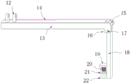
FIG. 1 is a schematic structural view of the appearance of a quick PC component lifting device of the present utility model;
FIG. 2 is a schematic structural view of a longitudinal adjustment mechanism of a quick PC component lifting device according to the present utility model;
FIG. 3 is a schematic structural view of a lateral adjustment mechanism portion of a quick PC component lifting device according to the present utility model;
FIG. 4 is a schematic view of the structure of the inside of a sliding frame of a quick PC component lifting device according to the present utility model;
in the figure: 1. a wire rope; 2. a slide bar; 3. a longitudinal adjustment mechanism; 4. a lateral adjustment mechanism; 5. clamping the assembly; 6. a sliding frame; 7. a sliding sleeve; 8. a threaded rod; 9. a hand wheel; 10. a telescoping passage; 11. adjusting the through hole; 12. a threaded sleeve; 13. an extension rod; 14. a rack; 15. a rotating shaft; 16. an abutting plate; 17. fixing the bayonet lock; 18. a pull rod; 19. a fixed baffle; 20. a spring; 21. a top clamping plate; 22. a bottom clamping plate; 23. and a linkage gear.
Detailed Description
The utility model is further described in connection with the following detailed description, in order to make the technical means, the creation characteristics, the achievement of the purpose and the effect of the utility model easy to understand.
Referring to fig. 1 to 4, the present utility model provides a technical solution: the utility model provides a PC component quick hoist device, includes the hoist device body, the hoist device body includes clamping subassembly 5, cable 1, vertical adjustment mechanism 3 and transverse adjustment mechanism 4, the top of vertical adjustment mechanism 3 is provided with sliding sleeve 7, rings are installed at sliding sleeve 7's top, the bottom of cable 1 is through this rings and vertical adjustment mechanism 3 part fixed connection, transverse adjustment mechanism 4 alternates to the inside of vertical adjustment mechanism 3, pull rod 18 is installed to the end of vertical adjustment mechanism 3, every independent clamping subassembly 5 is all installed to the bottom of pull rod 18, and this PC component quick hoist device utilizes a plurality of rings on the transverse adjustment mechanism 4 to be connected with the bottom fixed of many heel cable 1, then is connected with the hoist device of outside with cable 1 on top, and the PC component after the fixed butt joint in whole hoist device and bottom can be hung the hoist device through hoist device, and during the installation, need place the PC component in the bottom of this hoist device, utilize the independent subassembly 5 of every transverse adjustment mechanism 4 bottom to carry out fixed position to PC component side respectively, can finish the installation to the different position of PC component side, can finish the installation stability to the vertical adjustment mechanism 4 when installing the different size adjustment mechanism 3.
According to the embodiment, the longitudinal adjusting mechanism 3 comprises a sliding rod 2 and a sliding frame 6, the sliding sleeve 7 is arranged at the top of the sliding frame 6, the sliding rod 2 penetrates through the sliding sleeve 7, a telescopic channel 10 is arranged in the sliding frame 6, one end of the transverse adjusting mechanism 4 is inserted into the telescopic channel 10, an adjusting through hole 11 is formed in the top of the sliding frame 6, two sliding sleeves 7 are connected through a threaded rod 8, a hand wheel 9 is arranged at one end of the threaded rod 8, limiting plate structures are arranged at two ends of the sliding rod 2, two ends of the threaded rod 8 are embedded into the outer side of the sliding sleeve 7 through bearings, two groups of transverse adjusting mechanisms 4 with opposite directions are inserted into the longitudinal adjusting mechanism 3, clamping assemblies 5 at the bottom can be controlled to be clamped with the edges of PC components through control of the longitudinal adjusting mechanism 3 and the transverse adjusting mechanisms 4, so that the clamping firmness degree is improved, when PC components with different sizes are hoisted, the clamping assemblies can be directly controlled to extend along the sliding rod 2 according to the specific size of the longitudinal members, and the clamping positions of the clamping assemblies can be controlled to extend along the sliding rod 2.
In this embodiment, the transverse adjusting mechanism 4 includes an extension rod 13, a rack 14 and a linkage gear 23, the rack 14 is disposed on one side of the extension rod 13, a rotating shaft 15 is installed at one end of the extension rod 13, a clamping assembly 5 is disposed at the bottom of the rotating shaft 15, a threaded sleeve 12 is installed at the top of one of the extension rods 13 inside the sliding frame 6, the threaded sleeve 12 penetrates out from the inside of the adjusting through hole 11, the threaded sleeve 12 is sleeved on the surface of the threaded rod 8, the linkage gear 23 is installed in the middle of the sliding frame 6, the linkage gear 23 and the racks 14 on both sides are meshed with each other, two transverse adjusting mechanisms 4 can be simultaneously controlled to extend outwards by controlling a hand wheel 9 on the threaded rod 8, the adjusting step of the clamping fixing range is simplified, the application required by hoisting and docking is shortened, therefore, the quick hoisting effect is achieved, the alignment of the center point of the component and the rope at the top can be ensured, the offset probability is reduced, the adjustment range of the longitudinal clamping component 5 is realized in the moving process of the longitudinal adjusting mechanism 3, meanwhile, the hand wheel 9 drives the threaded rod 8 to rotate through rotating the hand wheel 9, the threaded sleeve 12 is slid by rotating the threaded rod 8, the extension rod 13 at the bottom is driven to outwards penetrate or retract, and meanwhile, the rack 14 at the other side and the extension rod 13 can be reversely moved under the action of the linkage gear 23 in the middle, so that the clamping components 5 at the two ends of the same longitudinal adjusting mechanism 3 always outwards extend for the same distance, and further, the alignment of the center position of the component and the steel cable 1 at the top can be ensured after the follow-up clamping.
According to the embodiment, the clamping assembly 5 comprises a pull rod 18 and a spring 20, two ends of the rotating shaft 15 are provided with abutting plates 16, the abutting plates 16 are penetrated with fixed clamping pins 17, a fixed baffle 19 and a bottom clamping plate 22 are welded and installed on one side of the bottom end of the pull rod 18, the spring 20 is connected to the bottom of the fixed baffle 19, the top clamping plate 21 is installed at the bottom end of the spring 20, the top clamping plate 21 and the bottom clamping plate 22 are aligned, the fixed clamping pins 17 penetrate through the surface of the abutting plates 16 and are embedded into the pull rod 18, the clamping assembly 5 at the bottom is used for clamping and fixing the edge of a framework, and as the dead weight of a member is far greater than the dead weight of the lifting device, the center of gravity is concentrated in the middle position of the member, the shaking amplitude in the lifting process of the member can be reduced, the safety is improved, and in particular, when clamping is carried out, the member is placed at the position between the top clamping plate 21 and the bottom clamping plate 22 by pulling the top clamping plate 21, then the top clamping plate 21 is loosened, namely the member can be fixed through the two clamping plates, and the clamping assembly 17 can be directly dismounted and the pull rod 18 can be directly dismounted, namely, the clamping assembly 17 can be directly dismounted and the pull rod 13 is directly, and the clamping assembly can be directly dismounted.
While the fundamental and principal features of the utility model and advantages of the utility model have been shown and described, it will be apparent to those skilled in the art that the utility model is not limited to the details of the foregoing exemplary embodiments, but may be embodied in other specific forms without departing from the spirit or essential characteristics thereof. The present embodiments are, therefore, to be considered in all respects as illustrative and not restrictive, the scope of the utility model being indicated by the appended claims rather than by the foregoing description, and all changes which come within the meaning and range of equivalency of the claims are therefore intended to be embraced therein. Any reference sign in a claim should not be construed as limiting the claim concerned.
Furthermore, it should be understood that although the present disclosure describes embodiments, not every embodiment is provided with a separate embodiment, and that this description is provided for clarity only, and that the disclosure is not limited to the embodiments described in detail below, and that the embodiments described in the examples may be combined as appropriate to form other embodiments that will be apparent to those skilled in the art.
Claims (8)
1. The utility model provides a quick hoist device of PC component, includes hoist device body, its characterized in that: hoist device body includes clamping subassembly (5), cable wire (1), vertical adjustment mechanism (3) and transverse adjustment mechanism (4), the top of vertical adjustment mechanism (3) is provided with slip sleeve (7), rings are installed at the top of slip sleeve (7), the bottom of cable wire (1) is through this rings and vertical adjustment mechanism (3) part fixed connection, transverse adjustment mechanism (4) alternates the inside of vertical adjustment mechanism (3), pull rod (18) are installed to the end of vertical adjustment mechanism (3), every independent clamping subassembly (5) are all installed to the bottom of pull rod (18).
2. The rapid PC component lifting device according to claim 1, wherein: the longitudinal adjusting mechanism (3) comprises a sliding rod (2) and a sliding frame (6), a sliding sleeve (7) is arranged at the top of the sliding frame (6), the sliding rod (2) penetrates through the sliding sleeve (7), a telescopic channel (10) is arranged in the sliding frame (6), and one end of the transverse adjusting mechanism (4) is inserted into the telescopic channel (10).
3. The rapid PC component lifting device according to claim 2, wherein: the top of sliding frame (6) has seted up regulation through-hole (11), two connect through threaded rod (8) between sliding sleeve (7), hand wheel (9) are installed to one end of threaded rod (8).
4. A PC component quick hoist as in claim 3, wherein: both ends of the sliding rod (2) are provided with limiting plate structures, both ends of the threaded rod (8) are embedded into the outer sides of the sliding sleeve (7) through bearings, and two groups of transverse adjusting mechanisms (4) with opposite directions are inserted into the longitudinal adjusting mechanisms (3).
5. The rapid PC component lifting device according to claim 2, wherein: the transverse adjusting mechanism (4) comprises an extension rod (13), a rack (14) and a linkage gear (23), wherein the rack (14) is arranged on one side of the extension rod (13), one end of the extension rod (13) is provided with a rotating shaft (15), and the bottom of the rotating shaft (15) is provided with a clamping assembly (5).
6. The rapid PC component lifting device of claim 5, wherein: the top of one of the extension rods (13) in the sliding frame (6) is provided with a threaded sleeve (12), the threaded sleeve (12) outwards penetrates out of the adjusting through hole (11), the threaded sleeve (12) is sleeved on the surface of the threaded rod (8), the middle of the sliding frame (6) is provided with a linkage gear (23), and the linkage gear (23) and racks (14) on two sides are meshed with each other.
7. The rapid PC component lifting device of claim 5, wherein: clamping subassembly (5) are including pull rod (18) and spring (20), the both ends of pivot (15) are provided with butt joint board (16), it has fixed bayonet lock (17) to alternate on butt joint board (16), fixed stop (19) and bottom splint (22) are installed in the bottom one side welding of pull rod (18), the bottom of fixed stop (19) is connected with spring (20).
8. The rapid PC component lifting device of claim 7, wherein: a top clamping plate (21) is installed at the bottom end of the spring (20), the top clamping plate (21) and the bottom clamping plate (22) are aligned, and the fixed clamping pin (17) is embedded into the pull rod (18) after penetrating through the surface of the butt plate (16).
Priority Applications (1)
| Application Number | Priority Date | Filing Date | Title |
|---|---|---|---|
| CN202320089624.XU CN219078841U (en) | 2023-01-31 | 2023-01-31 | Quick hoist device of PC component |
Applications Claiming Priority (1)
| Application Number | Priority Date | Filing Date | Title |
|---|---|---|---|
| CN202320089624.XU CN219078841U (en) | 2023-01-31 | 2023-01-31 | Quick hoist device of PC component |
Publications (1)
| Publication Number | Publication Date |
|---|---|
| CN219078841U true CN219078841U (en) | 2023-05-26 |
Family
ID=86406216
Family Applications (1)
| Application Number | Title | Priority Date | Filing Date |
|---|---|---|---|
| CN202320089624.XU Active CN219078841U (en) | 2023-01-31 | 2023-01-31 | Quick hoist device of PC component |
Country Status (1)
| Country | Link |
|---|---|
| CN (1) | CN219078841U (en) |
Cited By (1)
| Publication number | Priority date | Publication date | Assignee | Title |
|---|---|---|---|---|
| CN117585584A (en) * | 2024-01-18 | 2024-02-23 | 山西八建集团有限公司 | Lifting device for hoisting heavy steel structure |
-
2023
- 2023-01-31 CN CN202320089624.XU patent/CN219078841U/en active Active
Cited By (2)
| Publication number | Priority date | Publication date | Assignee | Title |
|---|---|---|---|---|
| CN117585584A (en) * | 2024-01-18 | 2024-02-23 | 山西八建集团有限公司 | Lifting device for hoisting heavy steel structure |
| CN117585584B (en) * | 2024-01-18 | 2024-03-22 | 山西八建集团有限公司 | Lifting device for hoisting heavy steel structure |
Similar Documents
| Publication | Publication Date | Title |
|---|---|---|
| CN219078841U (en) | Quick hoist device of PC component | |
| CN210714492U (en) | Engineering seepage slip casting is auxiliary positioning guider for drilling | |
| CN211006677U (en) | Cast-in-place pile pipe fixing device | |
| CN113503043B (en) | Assembly type building installation equipment | |
| CN214940060U (en) | Pile foundation steel reinforcement cage inclination correction equipment | |
| CN113982290A (en) | Assembled wall body mounting structure | |
| CN207829458U (en) | A kind of construction roof beam structure | |
| CN212031158U (en) | Tension detection device for building engineering | |
| CN111424899B (en) | Steel construction building stair fixed point installation support device | |
| CN215168203U (en) | Temporary reinforcing device for hoisting steel truss | |
| CN211371499U (en) | Metal pipeline support for steel structure engineering construction | |
| CN210164434U (en) | Multi-angle adjusting construction operation platform for jumbolter | |
| CN204290174U (en) | Specific purpose tool when installing for conducting rod | |
| CN111021702A (en) | Lifting scaffold unit | |
| CN108643044B (en) | Bridge High-pier turns over creeping formwork and cranks arm the passage method of crossbeam | |
| CN214527518U (en) | Traction type construction elevator synchronously lifted with building machine | |
| CN112125120B (en) | Auxiliary mobile butt-joint assembling equipment and method for hoisting steel truss | |
| CN114278071B (en) | Climbing frame for building construction | |
| CN220469397U (en) | Template support | |
| CN219603215U (en) | Auxiliary device for assembling security door | |
| CN213740644U (en) | Bridge reinforcing apparatus | |
| CN219195612U (en) | Steel box structure | |
| CN215946541U (en) | Portable liftable slope transportation article device | |
| CN219753030U (en) | Auxiliary safety device for hanging basket steel suspender | |
| CN220014375U (en) | Adjustable construction platform of bracing |
Legal Events
| Date | Code | Title | Description |
|---|---|---|---|
| GR01 | Patent grant | ||
| GR01 | Patent grant |