CN219074542U - Board cutting device with positioning unit for architectural decoration - Google Patents
Board cutting device with positioning unit for architectural decoration Download PDFInfo
- Publication number
- CN219074542U CN219074542U CN202222498002.0U CN202222498002U CN219074542U CN 219074542 U CN219074542 U CN 219074542U CN 202222498002 U CN202222498002 U CN 202222498002U CN 219074542 U CN219074542 U CN 219074542U
- Authority
- CN
- China
- Prior art keywords
- cutting device
- box body
- belt pulley
- positioning unit
- architectural decoration
- Prior art date
- Legal status (The legal status is an assumption and is not a legal conclusion. Google has not performed a legal analysis and makes no representation as to the accuracy of the status listed.)
- Active
Links
Images

Classifications
-
- Y—GENERAL TAGGING OF NEW TECHNOLOGICAL DEVELOPMENTS; GENERAL TAGGING OF CROSS-SECTIONAL TECHNOLOGIES SPANNING OVER SEVERAL SECTIONS OF THE IPC; TECHNICAL SUBJECTS COVERED BY FORMER USPC CROSS-REFERENCE ART COLLECTIONS [XRACs] AND DIGESTS
- Y02—TECHNOLOGIES OR APPLICATIONS FOR MITIGATION OR ADAPTATION AGAINST CLIMATE CHANGE
- Y02P—CLIMATE CHANGE MITIGATION TECHNOLOGIES IN THE PRODUCTION OR PROCESSING OF GOODS
- Y02P70/00—Climate change mitigation technologies in the production process for final industrial or consumer products
- Y02P70/10—Greenhouse gas [GHG] capture, material saving, heat recovery or other energy efficient measures, e.g. motor control, characterised by manufacturing processes, e.g. for rolling metal or metal working
Abstract
The utility model discloses a plate cutting device with a positioning unit for building decoration, which comprises a box body, a clamping and positioning mechanism and a driving mechanism; the box body comprises: the upper end of the box body is provided with a workbench surface, the middle part of the workbench surface is provided with a strip-shaped avoidance opening, the left side and the right side of the upper surface of the workbench surface are provided with sliding grooves, the inside of each sliding groove is slidably connected with a convex sliding block, the upper surface of each convex sliding block is respectively provided with a limiting block, the inside of the box body is rotationally connected with a connecting rod through a bearing, the middle part of the connecting rod is provided with a circular shaft, the middle part of the circular shaft is provided with a saw blade, the saw blade is matched with the strip-shaped avoidance opening, and the left end of the circular shaft is provided with a first belt pulley; clamping and positioning mechanism: the plate cutting device with the positioning unit for the architectural decoration is arranged on the upper surface of the limiting block, is simple in structure and convenient to operate, and is provided with the positioning clamping mechanism and the scale marks, so that the plate is cut more stably, and the cutting accuracy is improved.
Description
Technical Field
The utility model relates to the technical field of plate cutting, in particular to a plate cutting device with a positioning unit for architectural decoration.
Background
The plate is often used in the process of building decoration, but different decorations have different requirements on the length of the plate, and the large plate needs to be cut to meet the requirements on the size of the plate by different decorations, and the traditional cutting mode is manual pressing and cutting, so that the plate cutting device with the positioning unit for building decoration is time-consuming and labor-consuming, low in accuracy, large in error and capable of affecting the quality of products.
Disclosure of Invention
The utility model aims to overcome the existing defects, and provides the plate cutting device with the positioning unit for the building decoration, which has the advantages of simple structure, convenience in operation and capability of enabling the cutting of the plate to be more stable by additionally arranging the positioning clamping mechanism and the scale marks, thereby improving the cutting accuracy and effectively solving the problems in the background technology.
In order to achieve the above purpose, the present utility model provides the following technical solutions: a plate cutting device with a positioning unit for building decoration comprises a box body, a clamping and positioning mechanism and a driving mechanism;
the box body comprises: the upper end of the box body is provided with a workbench surface, the middle part of the workbench surface is provided with a strip-shaped avoidance opening, the left side and the right side of the upper surface of the workbench surface are provided with sliding grooves, the inside of each sliding groove is slidably connected with a convex sliding block, the upper surface of each convex sliding block is respectively provided with a limiting block, the inside of the box body is rotationally connected with a connecting rod through a bearing, the middle part of the connecting rod is provided with a circular shaft, the middle part of the circular shaft is provided with a saw blade, the saw blade is matched with the strip-shaped avoidance opening, and the left end of the circular shaft is provided with a first belt pulley;
clamping and positioning mechanism: the clamping and positioning mechanism is arranged on the upper surface of the limiting block and is positioned above the sliding groove;
a driving mechanism: the novel plate cutting machine is arranged in the box body, the driving mechanism is connected with the first belt pulley through a transmission belt in a transmission mode, the structure is simple, the operation is convenient, the positioning and clamping mechanism and the scale marks are additionally arranged, the cutting of the plate is more stable, and therefore the cutting accuracy is improved.
Further, the clamping and positioning mechanism comprises a round rotating block, a screw rod, a bar clamp plate, a -shaped clamping table and a round cap, wherein the -shaped clamping table is respectively arranged on the upper surface of the limiting block, the front side surfaces of the -shaped clamping tables are respectively connected with the screw rod in a threaded mode, the round cap is arranged at the front end of the screw rod, the round rotating block is arranged at the rear end of the screw rod, and two round rotating blocks located inside the same -shaped clamping table are respectively connected with the front end of one bar clamp plate in a rotating mode through a bearing and are clamped and positioned.
Further, the anti-skid device also comprises anti-skid grooves which are respectively arranged on the outer cambered surfaces of the round caps, so that the anti-skid device is convenient to further clamp.
Further, the electric control device also comprises a control switch, wherein the control switch is arranged on the right side of the upper surface of the working table, and the input end of the control switch is electrically connected with an external power supply to control the electric appliance.
Further, actuating mechanism includes motor mount pad, motor and second belt pulley, motor mount pad sets up in the diapire face middle part of box, and motor mount pad's inside is provided with the motor, and the output shaft of motor is provided with the second belt pulley, and the second belt pulley passes through drive belt and is connected with first belt pulley transmission, and the output of control switch is connected to the input electricity of motor, provides power.
Further, the diameter of the second belt pulley is larger than that of the first belt pulley, and the transmission efficiency is high.
Further, the automatic cutting machine also comprises scale marks, wherein the scale marks are respectively arranged in the middle of the workbench surface and are positioned on the left side and the right side of the strip-shaped avoiding opening, so that accurate cutting is facilitated.
Compared with the prior art, the utility model has the beneficial effects that: the plate cutting device with the positioning unit for the architectural decoration has the following advantages:
1. when the plate is required to be cut, the plate is respectively placed into the -shaped clamping table, the round caps are screwed clockwise with the same amplitude by both hands, the round caps which rotate clockwise drive the screw rod and the round rotating block to rotate, the screw rod is in threaded connection with the front side surface of the -shaped clamping table, and the screw rod which rotates clockwise drives the bar-shaped clamping plate to move backwards to clamp the plate.
2. At the moment, the motor is controlled to operate through the control switch, the output shaft of the motor drives the second belt pulley to rotate, the second belt pulley drives the first belt pulley to rotate through the transmission belt, the first belt pulley drives the circular shaft to enable the saw blade to rotate, at the moment, the connecting rod rotates in bearings on the left side and the right side of the box body, the -shaped clamping table is pushed, the -shaped clamping table slides backwards along the sliding groove on the convex sliding block fixedly connected with the limiting block to cut the plate, and meanwhile, the cutting size can be selected according to the scale marks.
Drawings
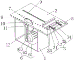
FIG. 1 is a schematic diagram of the structure of the present utility model;
FIG. 2 is a schematic view of the structure of the clamping and positioning mechanism and the driving mechanism of the present utility model;
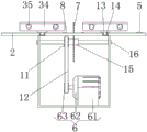
fig. 3 is a schematic diagram of the front view structure of the present utility model.
In the figure: the novel high-precision grinding machine comprises a box body 1, a workbench surface 2, a clamping and positioning mechanism 3, a round rotating block 31, a screw rod 32, a strip-shaped clamping plate 33, a strip-shaped clamping table 34 , a round cap 35, an anti-skid groove 4, a control switch 5, a driving mechanism 6, a motor mounting seat 61, a motor 62, a second belt pulley 63, a saw blade 7, a scale mark 8, a sliding groove 9, a strip-shaped avoiding opening 10, a first belt pulley 11, a driving belt 12, a limiting block 13, a convex sliding block 14, a round shaft 15 and a connecting rod 16.
Detailed Description
The following description of the embodiments of the present utility model will be made clearly and completely with reference to the accompanying drawings, in which it is apparent that the embodiments described are only some embodiments of the present utility model, but not all embodiments. All other embodiments, which can be made by those skilled in the art based on the embodiments of the utility model without making any inventive effort, are intended to be within the scope of the utility model.
Referring to fig. 1-3, the present embodiment provides a technical solution: a plate cutting device with a positioning unit for building decoration comprises a box body 1, a clamping and positioning mechanism 3 and a driving mechanism 6;
case 1: the upper end of the box body is provided with a workbench surface 2, the middle part of the workbench surface 2 is provided with a strip-shaped avoiding opening 10, the left side and the right side of the upper surface of the workbench surface 2 are provided with sliding grooves 9, the inside of each sliding groove 9 is slidably connected with a convex sliding block 14, the upper surfaces of the convex sliding blocks 14 are respectively provided with a limiting block 13, the inside of the box body 1 is rotatably connected with a connecting rod 16 through a bearing, the middle part of the connecting rod 16 is provided with a circular shaft 15, the middle part of the circular shaft 15 is provided with a saw blade 7, the saw blade 7 is matched with the strip-shaped avoiding opening 10, and the left end of the circular shaft 15 is provided with a first belt pulley 11;
clamping and positioning mechanism 3: the clamping and positioning mechanism 3 is arranged on the upper surface of the limiting block 13, the clamping and positioning mechanism 3 is arranged above the sliding groove 9, the clamping and positioning mechanism 3 comprises a circular rotating block 31, a screw rod 32, strip-shaped clamping plates 33, -shaped clamping plates 34 and circular caps 35, -shaped clamping plates 34 are respectively arranged on the upper surface of the limiting block 13, screw rods 32 are respectively connected with the front side surfaces of the -shaped clamping plates 34 in a threaded manner, the front ends of the screw rods 32 are respectively provided with the circular caps 35, the rear ends of the screw rods 32 are respectively provided with the circular rotating block 31, the two circular rotating blocks 31 positioned in the same -shaped clamping plates 34 are respectively connected with the front end of one strip-shaped clamping plate 33 in a rotating manner through bearings, the anti-sliding groove 4 is respectively arranged on the outer cambered surfaces of the circular caps 35, plates are respectively placed in the -shaped clamping plates 34, the circular caps 35 are screwed clockwise by two hands, the clockwise-rotated circular caps 35 drive the screw rods 32 to rotate in the circular rotating blocks 31 on the front side surfaces of the strip-shaped clamping plates 33, the screw rods 32 are connected with the front side surfaces of the -shaped clamping plates 34 in a threaded manner, and the clockwise-rotated screw rods 32 drive the screw rods 32 to move the front surfaces of the strip-shaped clamping plates 33 to move backwards to clamp plates 33;
wherein: the control switch 5 is arranged on the right side of the upper surface of the workbench surface 2, and the input end of the control switch 5 is electrically connected with an external power supply to control the electric appliance.
And a driving mechanism 6: the novel plate cutting machine is arranged in a box body 1, a driving mechanism 6 is in transmission connection with a first belt pulley 11 through a transmission belt 12, the driving mechanism 6 comprises a motor mounting seat 61, a motor 62 and a second belt pulley 63, the motor mounting seat 61 is arranged in the middle of the bottom wall surface of the box body 1, a motor 62 is arranged in the motor mounting seat 61, the second belt pulley 63 is arranged on an output shaft of the motor 62, the second belt pulley 63 is in transmission connection with the first belt pulley 11 through the transmission belt 12, the input end of the motor 62 is electrically connected with the output end of a control switch 5, the diameter of the second belt pulley 63 is larger than the diameter of the first belt pulley 11, when a plate is clamped and needs to be cut, the motor 62 is controlled to operate through the control switch 5, the output shaft of the motor 62 which operates drives the second belt pulley 63 to rotate, the first belt pulley 11 is driven by the first belt pulley 11 to rotate a circular shaft 15 to enable a saw blade 7 to rotate, and at the moment, a connecting rod 16 rotates in bearings on the left side and the right side of the box body 1.
Wherein: the cutting machine also comprises scale marks 8, wherein the scale marks 8 are respectively arranged in the middle of the workbench surface 2, the scale marks 8 are positioned on the left side and the right side of the strip-shaped avoiding opening 10, and the cutting machine can cut according to the size of the scale marks 8.
The utility model provides a plate cutting device with a positioning unit for building decoration, which has the following working principle: when the plate needs to be cut, the plate is respectively placed into -shaped clamping tables 34, two hands simultaneously screw the circular caps 35 clockwise with the same amplitude, the circular caps 35 rotating clockwise drive the screw rods 32 and the circular rotating blocks 31 to rotate, the screw rods 32 are in threaded connection with the front side surfaces of the -shaped clamping tables 34, the screw rods 32 rotating clockwise drive the bar-shaped clamping plates 33 to move backwards to clamp the plate, at the moment, the motor 62 is controlled to operate through the control switch 5, the output shaft of the operating motor 62 drives the second belt pulley 63 to rotate, the second belt pulley 63 drives the first belt pulley 11 to rotate through the transmission belt 12, the first belt pulley 11 drives the circular shaft 15 to enable the saw blade 7 to rotate, at the moment, the connecting rod 16 rotates in bearings on the left side and the right side of the box body 1 to push the -shaped clamping tables 34, the -shaped clamping tables 34 slide backwards on the convex sliding blocks 14 fixedly connected with the limiting blocks 13 along the sliding grooves 9 to cut the plate, and at the same time, the size cutting can be selected according to the scale marks 8 can be achieved.
It should be noted that the motor 62 disclosed in the above embodiment may be S-J5.5KW4P, and the control switch 5 is provided with a control button corresponding to the motor 62 for controlling the switch thereof.
The foregoing description is only illustrative of the present utility model and is not intended to limit the scope of the utility model, and all equivalent structures or equivalent processes or direct or indirect application in other related technical fields are included in the scope of the present utility model.
Claims (7)
1. The utility model provides a panel cutting device of area positioning unit for architectural decoration which characterized in that: comprises a box body (1), a clamping and positioning mechanism (3) and a driving mechanism (6);
box (1): the upper end of the box body is provided with a workbench surface (2), the middle part of the workbench surface (2) is provided with a strip-shaped avoidance opening (10), sliding grooves (9) are formed in the left side and the right side of the upper surface of the workbench surface (2), convex sliding blocks (14) are slidably connected in the sliding grooves (9), limiting blocks (13) are respectively arranged on the upper surface of the convex sliding blocks (14), connecting rods (16) are rotatably connected in the box body (1) through bearings, the middle part of each connecting rod (16) is provided with a circular shaft (15), the middle part of each circular shaft (15) is provided with a saw blade (7), the saw blade (7) is matched with the strip-shaped avoidance opening (10), and a first belt pulley (11) is arranged at the left end of each circular shaft (15);
clamping and positioning mechanism (3): the clamping and positioning mechanism (3) is arranged on the upper surface of the limiting block (13) and is positioned above the sliding groove (9);
drive mechanism (6): the novel box is arranged in the box body (1), and the driving mechanism (6) is in transmission connection with the first belt pulley (11) through a transmission belt (12).
2. The sheet cutting device with a positioning unit for architectural decoration according to claim 1, wherein: the clamping and positioning mechanism (3) comprises a circular rotating block (31), a screw rod (32), a bar clamp plate (33), -shaped clamping tables (34) and a circular cap (35), wherein the -shaped clamping tables (34) are respectively arranged on the upper surface of a limiting block (13), the front side surfaces of the -shaped clamping tables (34) are respectively connected with the screw rod (32) in a threaded manner, the front end of the screw rod (32) is provided with the circular cap (35), the rear end of the screw rod (32) is provided with the circular rotating block (31), and two circular rotating blocks (31) positioned in the same -shaped clamping table (34) are respectively connected with the front end of one bar clamp plate (33) in a rotating manner through bearings.
3. The sheet cutting device with a positioning unit for architectural decoration according to claim 2, wherein: the novel anti-skid cap further comprises anti-skid grooves (4), and the anti-skid grooves (4) are respectively arranged on the outer cambered surfaces of the round caps (35).
4. The sheet cutting device with a positioning unit for architectural decoration according to claim 1, wherein: the automatic control device is characterized by further comprising a control switch (5), wherein the control switch (5) is arranged on the right side of the upper surface of the workbench surface (2), and the input end of the control switch (5) is electrically connected with an external power supply.
5. The sheet cutting device with a positioning unit for architectural decoration according to claim 4, wherein: the driving mechanism (6) comprises a motor mounting seat (61), a motor (62) and a second belt pulley (63), wherein the motor mounting seat (61) is arranged in the middle of the bottom wall surface of the box body (1), a motor (62) is arranged in the motor mounting seat (61), a second belt pulley (63) is arranged on an output shaft of the motor (62), and the second belt pulley (63) is in transmission connection with the first belt pulley (11) through a transmission belt (12), and the input end of the motor (62) is electrically connected with the output end of the control switch (5).
6. The sheet cutting device with a positioning unit for architectural decoration according to claim 5, wherein: the diameter of the second pulley (63) is larger than that of the first pulley (11).
7. The sheet cutting device with a positioning unit for architectural decoration according to claim 1, wherein: the automatic weighing machine further comprises scale marks (8), wherein the scale marks (8) are respectively arranged in the middle of the workbench surface (2), and the scale marks (8) are positioned on the left side and the right side of the strip-shaped avoidance opening (10).
Priority Applications (1)
| Application Number | Priority Date | Filing Date | Title |
|---|---|---|---|
| CN202222498002.0U CN219074542U (en) | 2022-09-21 | 2022-09-21 | Board cutting device with positioning unit for architectural decoration |
Applications Claiming Priority (1)
| Application Number | Priority Date | Filing Date | Title |
|---|---|---|---|
| CN202222498002.0U CN219074542U (en) | 2022-09-21 | 2022-09-21 | Board cutting device with positioning unit for architectural decoration |
Publications (1)
| Publication Number | Publication Date |
|---|---|
| CN219074542U true CN219074542U (en) | 2023-05-26 |
Family
ID=86388769
Family Applications (1)
| Application Number | Title | Priority Date | Filing Date |
|---|---|---|---|
| CN202222498002.0U Active CN219074542U (en) | 2022-09-21 | 2022-09-21 | Board cutting device with positioning unit for architectural decoration |
Country Status (1)
| Country | Link |
|---|---|
| CN (1) | CN219074542U (en) |
-
2022
- 2022-09-21 CN CN202222498002.0U patent/CN219074542U/en active Active
Similar Documents
| Publication | Publication Date | Title |
|---|---|---|
| CN220432628U (en) | Limiting component of high-precision cutting machine for glass substrate | |
| CN219074542U (en) | Board cutting device with positioning unit for architectural decoration | |
| CN113305888A (en) | Cutting device is used in printed circuit board processing with arrange board function | |
| CN216913077U (en) | High-precision full-automatic cutting device | |
| CN216729854U (en) | Portable multifunctional sawing machine | |
| CN214925282U (en) | Slicing device capable of cutting at fixed distance for wood processing | |
| CN211891494U (en) | Cutting machine is used in building board production | |
| CN208697546U (en) | A kind of full-automatic dedicated cutting equipment that light modulation film is cut | |
| CN211590484U (en) | Door pocket processingequipment | |
| CN208664013U (en) | Disconnecting device is used in a kind of processing of timber | |
| CN207757883U (en) | A kind of portable high-efficiency ceramic tile cutter | |
| CN112453951A (en) | Equidistant cutting equipment is used in ball processing | |
| CN214293372U (en) | Positioning mechanism of bead cutter is used in production of sauce vinegar bottle | |
| CN212602089U (en) | Novel cutting equipment of environmental protection material | |
| CN110614679A (en) | Door pocket processingequipment | |
| CN216615284U (en) | Medical adhesive tape production cutting device | |
| CN218311238U (en) | Chamfering tool for processing positioning ring | |
| CN216229800U (en) | Production device for polymer film adhesive labels | |
| CN219837838U (en) | Rubber and plastic cutting machine | |
| CN220388036U (en) | Mechanical automation cuts device | |
| CN214819277U (en) | Cutting machine convenient for processing fixed furniture board | |
| CN213165571U (en) | Cutting device is used in processing of mould panel | |
| CN219950837U (en) | Glass product processing and cutting device | |
| CN216177116U (en) | High-precision numerical control plate shearing machine with adjustable blades | |
| CN219766928U (en) | Metal product cutting machine with clamping structure |
Legal Events
| Date | Code | Title | Description |
|---|---|---|---|
| GR01 | Patent grant | ||
| GR01 | Patent grant |