CN219058573U - Waste water treatment device - Google Patents
Waste water treatment device Download PDFInfo
- Publication number
- CN219058573U CN219058573U CN202223399561.2U CN202223399561U CN219058573U CN 219058573 U CN219058573 U CN 219058573U CN 202223399561 U CN202223399561 U CN 202223399561U CN 219058573 U CN219058573 U CN 219058573U
- Authority
- CN
- China
- Prior art keywords
- water inlet
- mixing
- cylinder
- fixed
- water
- Prior art date
- Legal status (The legal status is an assumption and is not a legal conclusion. Google has not performed a legal analysis and makes no representation as to the accuracy of the status listed.)
- Active
Links
- 238000004065 wastewater treatment Methods 0.000 title claims abstract description 22
- XLYOFNOQVPJJNP-UHFFFAOYSA-N water Substances O XLYOFNOQVPJJNP-UHFFFAOYSA-N 0.000 claims abstract description 142
- 238000002156 mixing Methods 0.000 claims abstract description 109
- 239000002351 wastewater Substances 0.000 claims abstract description 66
- 238000001914 filtration Methods 0.000 claims abstract description 53
- 238000003756 stirring Methods 0.000 claims abstract description 42
- 238000000746 purification Methods 0.000 claims abstract description 31
- 239000003814 drug Substances 0.000 claims abstract description 22
- 229940079593 drug Drugs 0.000 claims abstract description 8
- 239000002893 slag Substances 0.000 claims description 7
- 238000007790 scraping Methods 0.000 claims description 5
- 239000010812 mixed waste Substances 0.000 abstract description 2
- OKTJSMMVPCPJKN-UHFFFAOYSA-N Carbon Chemical compound [C] OKTJSMMVPCPJKN-UHFFFAOYSA-N 0.000 description 5
- 239000007788 liquid Substances 0.000 description 3
- 239000011148 porous material Substances 0.000 description 3
- 235000017166 Bambusa arundinacea Nutrition 0.000 description 2
- 235000017491 Bambusa tulda Nutrition 0.000 description 2
- 241001330002 Bambuseae Species 0.000 description 2
- 229920000742 Cotton Polymers 0.000 description 2
- 235000015334 Phyllostachys viridis Nutrition 0.000 description 2
- 239000000654 additive Substances 0.000 description 2
- 230000000996 additive effect Effects 0.000 description 2
- 239000011425 bamboo Substances 0.000 description 2
- 239000013049 sediment Substances 0.000 description 2
- 239000000126 substance Substances 0.000 description 2
- 238000013019 agitation Methods 0.000 description 1
- QVGXLLKOCUKJST-UHFFFAOYSA-N atomic oxygen Chemical compound [O] QVGXLLKOCUKJST-UHFFFAOYSA-N 0.000 description 1
- 230000009286 beneficial effect Effects 0.000 description 1
- 230000000903 blocking effect Effects 0.000 description 1
- 229910052799 carbon Inorganic materials 0.000 description 1
- 230000007547 defect Effects 0.000 description 1
- 238000010586 diagram Methods 0.000 description 1
- 239000008187 granular material Substances 0.000 description 1
- 238000000034 method Methods 0.000 description 1
- 238000012986 modification Methods 0.000 description 1
- 230000004048 modification Effects 0.000 description 1
- 239000001301 oxygen Substances 0.000 description 1
- 229910052760 oxygen Inorganic materials 0.000 description 1
Images


Classifications
-
- Y—GENERAL TAGGING OF NEW TECHNOLOGICAL DEVELOPMENTS; GENERAL TAGGING OF CROSS-SECTIONAL TECHNOLOGIES SPANNING OVER SEVERAL SECTIONS OF THE IPC; TECHNICAL SUBJECTS COVERED BY FORMER USPC CROSS-REFERENCE ART COLLECTIONS [XRACs] AND DIGESTS
- Y02—TECHNOLOGIES OR APPLICATIONS FOR MITIGATION OR ADAPTATION AGAINST CLIMATE CHANGE
- Y02W—CLIMATE CHANGE MITIGATION TECHNOLOGIES RELATED TO WASTEWATER TREATMENT OR WASTE MANAGEMENT
- Y02W10/00—Technologies for wastewater treatment
- Y02W10/10—Biological treatment of water, waste water, or sewage
Landscapes
- Filtration Of Liquid (AREA)
Abstract
The utility model relates to the technical field of wastewater purification, in particular to a wastewater treatment device; the device comprises a purifying unit, a mixing unit and a stirring unit, wherein the purifying unit comprises a purifying box and a filtering module, and the filtering module is fixed in the purifying box and divides the inside of the purifying box into a water inlet cavity and a water outlet cavity; the mixing unit comprises a water inlet cylinder and a mixing cylinder, the water inlet cylinder is fixed on the purifying box and is positioned on the periphery of the water inlet, the mixing cylinder can be driven to rotate by the stirring unit, waste water and medicines are added into the mixing cylinder and then mixed, the mixed waste water enters a gap between the water inlet cylinder and the mixing cylinder from a first filtering hole of the mixing cylinder, finally, the waste water is introduced into the water inlet cavity from the water inlet, filtered by the filtering module and then enters the water draining cavity, finally, the waste water is discharged through the water draining port, and through the arrangement of the first filtering hole on the mixing cylinder, the waste water can be effectively filtered before the waste water passes through the water inlet cavity, so that the blockage caused by filter residues to the filtering module can be reduced, and the purification cost of the waste water is reduced.
Description
Technical Field
The utility model relates to the technical field of wastewater purification, in particular to a wastewater treatment device.
Background
Along with the development of the urban, technological and humanized society, the industrial industry is vigorously developed, and the wastewater pollution problem is revealed, so that the wastewater is required to be purified by wastewater treatment equipment before being discharged in order to reduce the pollution caused by the wastewater.
The utility model discloses a waste water treatment device with waste water reuse function as disclosed in the prior patent with publication number CN213623714U, the device adds chemical additive through adding the mouth to the agitator tank inside, reacts with waste water, simultaneously, and pivot and puddler evenly stir waste water and chemical additive inside the device, then filter the granule in the waste water through filter screen and active carbon filtration cotton again, and then realize purifying waste water.
However, the wastewater treatment device directly leads the wastewater to the filter modules such as the filter screen, the activated carbon filter cotton and the like for filtering after the wastewater is mixed with the medicines, so that the filter modules are easy to be blocked, further the filter modules are invalid, and the purification cost of the wastewater is increased.
Disclosure of Invention
The utility model aims to overcome the technical defects, and provides a wastewater treatment device which solves the technical problem that the filtering module is easy to be blocked in the wastewater purification process of the wastewater treatment device in the prior art, so that the purification cost of wastewater is increased.
In order to achieve the technical purpose, the technical scheme of the utility model provides a wastewater treatment device, which comprises:
the purification unit comprises a purification box and a filtering module, wherein the filtering module is arranged in the purification box and separates the interior of the purification box to form a water inlet cavity and a water outlet cavity, the filtering module is used for filtering wastewater entering the water outlet cavity through the water inlet cavity, and the surface of the purification box is provided with a water inlet and a water outlet which are respectively communicated with the water inlet cavity and the water outlet cavity;
the mixing unit comprises a water inlet cylinder and a mixing cylinder, the water inlet cylinder is fixed on the purifying box and positioned at the periphery of the water inlet, the mixing cylinder is positioned in the water inlet cylinder and is arranged at intervals with the water inlet cylinder, and a plurality of first filtering holes are formed in the circumferential direction of the mixing cylinder for adding medicines and waste water;
and the stirring unit is connected with the mixing drum and used for driving the mixing drum to rotate.
Optionally, the stirring unit includes motor, drive belt and first pivot, the motor is fixed in the purifying box, first pivot is fixed in the mixing drum, the one end cover of drive belt is located the spindle of motor, the other end cover of drive belt is located first pivot.
Optionally, the stirring unit further comprises a first stirring blade, the end part of the first rotating shaft extends to the water inlet cavity through the water inlet, and the first stirring blade is fixed on the first rotating shaft and is located at one end of the water inlet cavity.
Optionally, the water inlet is fixed with a water inlet guide cylinder, and the water inlet guide cylinder extends to the water inlet cavity and is located on the periphery side of the first stirring blade.
Optionally, the stirring unit further comprises a second rotating shaft and a second stirring blade, wherein the second rotating shaft is fixed on the shaft of the motor and is positioned in the water inlet cavity, and the second stirring blade is fixed on the second rotating shaft.
Optionally, the mixing unit further comprises a mixing rack fixed to the bottom wall of the mixing drum and extending in a curved manner towards the side wall of the mixing drum.
Optionally, the mixing unit further comprises a dosing cartridge fixed to the water inlet cartridge and extending to the bottom wall of the mixing cartridge for dosing the mixing cartridge.
Optionally, the mixing unit scrapes the sediment frame, scrape the sediment frame and be fixed in the inboard of intaking section of thick bamboo and extend to one side of first filtration pore, be used for through the rotation of mixing section of thick bamboo scrapes the filter residue of first filtration pore.
Optionally, the mixing unit further comprises a filter frame, the filter frame is fixed on the inner wall of the water inlet cylinder and located between the water inlet cylinder and the mixing cylinder, the filter frame extends along the circumferential direction of the mixing cylinder, and a plurality of second filter holes are formed in the surface of the filter frame.
Optionally, the filtration module includes first filter, and is fixed in perpendicularly the second filter of first filter, first filter with the second filter is all fixed in the inner wall of purifying box, first filter the second filter with the inner wall of purifying box encloses and closes and form the drainage chamber.
Compared with the prior art, the wastewater treatment device provided by the utility model has the beneficial effects that: the purifying unit comprises a purifying box and a filtering module, wherein the filtering module is fixed in the purifying box and divides the inside of the purifying box into a water inlet cavity and a water outlet cavity, and the surface of the purifying box is provided with a water inlet and a water outlet which are respectively communicated with the water inlet cavity and the water outlet cavity; the mixing unit comprises a water inlet cylinder and a mixing cylinder, the water inlet cylinder is fixed on the purifying box and is positioned at the periphery of the water inlet, the mixing cylinder is positioned in the water inlet cylinder and is arranged at intervals with the water inlet cylinder, the mixing unit can drive the mixing cylinder to rotate, after wastewater and medicines are added into the mixing cylinder, the mixing unit drives the mixing cylinder to rotate, so that the wastewater and the medicines are fully mixed, the mixed wastewater enters a gap between the water inlet cylinder and the mixing cylinder from a first filtering hole of the mixing cylinder, finally, the wastewater is introduced into the water inlet cavity from the water inlet, filtered by the filtering module and then enters the water outlet cavity, and finally, the wastewater is discharged through the water outlet, thereby realizing the purification of the wastewater; through the setting of first filtration pore on the mixing drum, can effectively filter waste water before waste water passes through the inlet chamber, and then can alleviate the jam that filter residue caused filtration module, reduce the purification cost of waste water.
Drawings
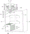
Fig. 1 is a schematic structural diagram of a wastewater treatment apparatus according to an embodiment of the present utility model.
Fig. 2 is a front view of a wastewater treatment apparatus according to an embodiment of the present utility model.
Fig. 3 is a cross-sectional view taken along line A-A in fig. 2.
Wherein, each reference sign in the figure:
10-purifying unit 11-purifying box 12-filtering module
20-mixing unit 21-water inlet cylinder 22-mixing cylinder
23-filter frame 24-slag scraping frame 25-mixing frame
26-cartridge 30-stirring unit 31-motor
32-drive belt 33-first rotating shaft 34-first stirring vane
35-second rotating shaft 36-second stirring vane 111-water inlet cavity
112-drainage cavity 113-water inlet 114-water outlet
115-inlet guide cylinder 121-first filter plate 122-second filter plate
211-a fixing frame 221-a first filtering hole 231-a second filtering hole.
Detailed Description
The present utility model will be described in further detail with reference to the drawings and examples, in order to make the objects, technical solutions and advantages of the present utility model more apparent. It should be understood that the specific embodiments described herein are for purposes of illustration only and are not intended to limit the scope of the utility model.
The utility model provides a wastewater treatment device, which comprises a purification unit 10, a mixing unit 20 and a stirring unit 30, wherein the purification unit 10 comprises a purification tank 11 and a filtering module 12, the filtering module 12 is arranged in the purification tank 11 and divides the interior of the purification tank 11 into a water inlet cavity 111 and a water outlet cavity 112, the filtering module 12 is used for filtering wastewater entering the water outlet cavity 112 through the water inlet cavity 111, and the surface of the purification tank 11 is provided with a water inlet 113 and a water outlet 114 which are respectively communicated with the water inlet cavity 111 and the water outlet cavity 112; the mixing unit 20 comprises a water inlet cylinder 21 and a mixing cylinder 22, wherein the water inlet cylinder 21 is fixed on the purifying box 11 and is positioned at the periphery of the water inlet 113, the mixing cylinder 22 is positioned in the water inlet cylinder 21 and is arranged at intervals with the water inlet cylinder 21, a plurality of first filtering holes 221 are formed in the circumferential direction of the mixing cylinder 22, and the water inlet cylinder 21 is used for adding medicines and wastewater; the stirring unit 30 is connected to the mixing drum 22 for driving the mixing drum 22 to rotate.
Specifically, by providing the purifying unit 10, the mixing unit 20 and the stirring unit 30, the purifying unit 10 includes the purifying tank 11 and the filter module 12, the filter module 12 is installed inside the purifying tank 11, and separates the inside of the purifying tank 11 to form the water inlet chamber 111 and the water outlet chamber 112, and the surface of the purifying tank 11 is provided with the water inlet 113 and the water outlet 114 which are respectively communicated with the water inlet chamber 111 and the water outlet chamber 112; the mixing unit 20 comprises a water inlet cylinder 21 and a mixing cylinder 22, the water inlet cylinder 21 is fixed on the purifying box 11 and is positioned at the periphery of the water inlet 113, the mixing cylinder 22 is positioned in the water inlet cylinder 21 and is arranged at intervals with the water inlet cylinder 21, the mixing unit 30 can drive the mixing cylinder 22 to rotate, after the wastewater and the medicine are added into the mixing cylinder 22, the mixing unit 30 drives the mixing cylinder 22 to rotate, the wastewater and the medicine are fully mixed, the mixed wastewater enters a gap between the water inlet cylinder 21 and the mixing cylinder 22 from a first filtering hole 221 of the mixing cylinder 22, finally, the wastewater is introduced into the water inlet cavity 111 from the water inlet 113, filtered by the filtering module 12 and enters the water discharge cavity 112, and finally, the wastewater is discharged through the water discharge port 114, so that the wastewater is purified; through the arrangement of the first filtering holes 221 on the mixing drum 22, the waste water can be effectively filtered before passing through the water inlet cavity 111, so that the blockage of filter residues to the filtering module 12 can be reduced, and the purification cost of the waste water can be reduced.
In this embodiment, the filter module 12 includes a first filter plate 121 and a second filter plate 122 vertically fixed to the first filter plate 121, the first filter plate 121 and the second filter plate 122 are both fixed to the inner wall of the purifying box 11, and the inner walls of the first filter plate 121, the second filter plate 122 and the purifying box 11 enclose to form the drainage cavity 112. Specifically, by arranging the filter module 12 as the first filter plate 121 and the second filter plate 122 perpendicular to the first filter plate 121, the multi-angle filtration of the wastewater in the water inlet cavity 111 can be realized, and the filtration efficiency of the filter module 12 can be improved.
It will be appreciated that the first filter plate 121 and the second filter plate 122 may be any structure capable of filtering wastewater, such as an activated carbon plate, a filter screen, etc.
In this embodiment, the upper end of the mixing drum 22 is provided with an opening for facilitating the supply of oxygen and waste water.
In this embodiment, in order to prevent waste water from directly entering the gap between the mixing drum 22 and the water inlet drum 21 from the upper end opening of the mixing drum 22 without being filtered by the first filter hole 221, the mixing unit 20 is further provided with a filter frame 23, the filter frame 23 is fixed to the inner wall of the water inlet drum 21 and located between the water inlet drum 21 and the mixing drum 22, the filter frame 23 extends along the circumferential direction of the mixing drum 22, and the surface of the filter frame 23 is provided with a plurality of second filter holes 231. Specifically, by the provision of the second filtering holes 231, the waste water flowing out of the upper end opening of the mixing drum 22 can be filtered by the filter frame 23 and then enter the water inlet 113.
In the present embodiment, the mixing unit 20 scrapes the slag frame 24, and the slag frame 24 is fixed to the inner side of the water inlet drum 21 and extends to one side of the first filtering holes 221 for scraping the residues of the first filtering holes 221 by the rotation of the mixing drum 22. Specifically, as the mixing drum 22 rotates, the slag scraping frame 24 can scrape slag on the mixing drum 22, so as to effectively avoid blocking the first filtering holes 221 by the slag.
In this embodiment, the mixing unit 20 further includes a mixing frame 25, and the mixing frame 25 is fixed to the bottom wall of the mixing drum 22 and extends in a curved manner toward the side wall of the mixing drum 22. Specifically, when the mixing drum 22 rotates, the mixing rack 25 can be driven to rotate, so that the medicine and the wastewater can be fully mixed, and the purification efficiency of the wastewater can be improved.
In this embodiment, the mixing unit 20 further comprises a dosing cartridge 26, the dosing cartridge 26 being fixed to the water inlet cartridge 21 and extending to the bottom wall of the mixing cartridge 22 for dosing the mixing cartridge 22. Specifically, when wastewater purification is performed, the medicine can be added to the mixing drum 22 through the medicine adding drum 26, and since the medicine adding drum 26 extends to the bottom wall of the mixing drum 22, the medicine can be directly added to the bottom wall of the mixing drum 22, and under the stirring of the mixing rack 25 at the bottom wall of the medicine adding drum 26, the medicine and the wastewater can be fully mixed.
In this embodiment, further, a fixing frame 211 is disposed inside the water inlet tube 21, and the medicine feeding tube 26 is fixed on the fixing frame 211.
In this embodiment, the stirring unit 30 includes a motor 31, a driving belt 32 and a first rotating shaft 33, the motor 31 is fixed on the purifying box 11, the first rotating shaft 33 is fixed on the mixing drum 22, one end of the driving belt 32 is sleeved on the shaft of the motor 31, and the other end of the driving belt 32 is sleeved on the first rotating shaft 33. Specifically, when the motor 31 is started, the driving belt 32 drives the first rotating shaft 33 to rotate, so as to drive the mixing drum 22 to rotate.
In this embodiment, the stirring unit 30 further includes a first stirring blade 34, and an end portion of the first rotating shaft 33 extends to the water inlet cavity 111 through the water inlet 113, and the first stirring blade 34 is fixed to the first rotating shaft 33 and located at one end of the water inlet cavity 111. Specifically, the first stirring blade 34 is arranged on the first rotating shaft 33 extending to the water inlet cavity 111, so that after the wastewater enters the water inlet cavity 111 from the water inlet 113, the wastewater can be stirred by the first stirring blade 34, the drug and the wastewater are further fully mixed, and the purification efficiency of the wastewater is improved.
In the present embodiment, the water inlet 113 is fixed with a water inlet guide cylinder 115, and the water inlet guide cylinder 115 extends to the water inlet chamber 111 and is located on the circumferential side of the first stirring blade 34. Specifically, the inlet guide cylinder 115 may limit the wastewater entering through the water inlet 113 to facilitate the agitation of the first agitating blade 34.
In this embodiment, the stirring unit 30 further includes a second rotating shaft 35 and a second stirring blade 36, the second rotating shaft 35 is fixed to the shaft of the motor 31 and is located in the water inlet cavity 111, and the second stirring blade 36 is fixed to the second rotating shaft 35. Specifically, after the wastewater enters the water inlet cavity 111 through the water inlet 113, the wastewater can be further stirred by the second stirring blade 36, so as to further improve the purification efficiency of the wastewater.
The specific working process of the utility model is as follows: when the waste water purifying operation is carried out, the waste water passes through the mixing drum 22, is introduced into the medicine adding drum 26 and mixed with the liquid medicine under the rotation of the mixing drum 22, the mixed waste water and the liquid medicine are filtered by the first filtering holes 221 or the second filtering holes 231 and enter a gap between the water inlet drum 21 and the mixing drum 22, then flow to the water inlet 113, enter the water inlet cavity 111 after being stirred by the first stirring blades 34 at the water inlet 113, fully mix the waste water and the liquid medicine under the stirring of the second stirring blades 36 of the water inlet cavity 111, finally enter the water discharge cavity 112 after being filtered by the first filtering plate 121 and the second filtering plate 122, so that the waste water is fully purified, and the purified waste water is finally discharged from the water outlet 114.
The above-described embodiments of the present utility model do not limit the scope of the present utility model. Any other corresponding changes and modifications made in accordance with the technical idea of the present utility model shall be included in the scope of the claims of the present utility model.
Claims (10)
1. A wastewater treatment apparatus, comprising:
the purification unit comprises a purification box and a filtering module, wherein the filtering module is arranged in the purification box and separates the interior of the purification box to form a water inlet cavity and a water outlet cavity, the filtering module is used for filtering wastewater entering the water outlet cavity through the water inlet cavity, and the surface of the purification box is provided with a water inlet and a water outlet which are respectively communicated with the water inlet cavity and the water outlet cavity;
the mixing unit comprises a water inlet cylinder and a mixing cylinder, the water inlet cylinder is fixed on the purifying box and positioned on the periphery of the water inlet, the mixing cylinder is positioned in the water inlet cylinder and is arranged at intervals with the water inlet cylinder, the water inlet cylinder is used for adding medicines and wastewater, and a plurality of first filtering holes are formed in the circumferential direction of the mixing cylinder;
and the stirring unit is connected with the mixing drum and used for driving the mixing drum to rotate.
2. The wastewater treatment device according to claim 1, wherein the stirring unit comprises a motor, a driving belt and a first rotating shaft, the motor is fixed on the purifying box, the first rotating shaft is fixed on the mixing drum, one end of the driving belt is sleeved on a shaft of the motor, and the other end of the driving belt is sleeved on the first rotating shaft.
3. The wastewater treatment apparatus according to claim 2, wherein the stirring unit further comprises a first stirring blade, an end portion of the first rotating shaft extends to the water inlet chamber via the water inlet, and the first stirring blade is fixed to the first rotating shaft at one end of the water inlet chamber.
4. A wastewater treatment apparatus according to claim 3, wherein the water inlet is fixed with a water inlet guide tube extending to the water inlet chamber and located on the circumferential side of the first stirring blade.
5. The wastewater treatment apparatus of claim 2, wherein the stirring unit further comprises a second rotating shaft and a second stirring blade, the second rotating shaft being fixed to a shaft of the motor and positioned in the water inlet chamber, the second stirring blade being fixed to the second rotating shaft.
6. The apparatus according to any one of claims 1 to 5, wherein the mixing unit further comprises a mixing frame fixed to a bottom wall of the mixing drum and extending in a curved manner toward a side wall of the mixing drum.
7. The wastewater treatment apparatus of any one of claims 1-5, wherein the mixing unit further comprises a dosing cartridge secured to the water inlet cartridge and extending to a bottom wall of the mixing cartridge for dosing the mixing cartridge.
8. The wastewater treatment apparatus according to any one of claims 1 to 5, wherein the mixing unit is a slag scraping frame fixed to an inner side of the water inlet pipe and extending to one side of the first filtering hole, for scraping off residues of the first filtering hole by rotation of the mixing pipe.
9. The apparatus according to any one of claims 1 to 5, wherein the mixing unit further comprises a filter frame fixed to an inner wall of the water inlet tube and located between the water inlet tube and the mixing tube, the filter frame extending in a circumferential direction of the mixing tube, and a surface of the filter frame is provided with a plurality of second filter holes.
10. The wastewater treatment apparatus according to any one of claims 1 to 5, wherein the filter module includes a first filter plate and a second filter plate vertically fixed to the first filter plate, the first filter plate and the second filter plate are both fixed to an inner wall of the purification tank, and the first filter plate, the second filter plate and the inner wall of the purification tank enclose the drainage chamber.
Priority Applications (1)
| Application Number | Priority Date | Filing Date | Title |
|---|---|---|---|
| CN202223399561.2U CN219058573U (en) | 2022-12-13 | 2022-12-13 | Waste water treatment device |
Applications Claiming Priority (1)
| Application Number | Priority Date | Filing Date | Title |
|---|---|---|---|
| CN202223399561.2U CN219058573U (en) | 2022-12-13 | 2022-12-13 | Waste water treatment device |
Publications (1)
| Publication Number | Publication Date |
|---|---|
| CN219058573U true CN219058573U (en) | 2023-05-23 |
Family
ID=86363085
Family Applications (1)
| Application Number | Title | Priority Date | Filing Date |
|---|---|---|---|
| CN202223399561.2U Active CN219058573U (en) | 2022-12-13 | 2022-12-13 | Waste water treatment device |
Country Status (1)
| Country | Link |
|---|---|
| CN (1) | CN219058573U (en) |
-
2022
- 2022-12-13 CN CN202223399561.2U patent/CN219058573U/en active Active
Similar Documents
| Publication | Publication Date | Title |
|---|---|---|
| CN216639126U (en) | PCB circuit board effluent treatment plant | |
| CN108503070A (en) | A kind of anticlogging sewage-treatment plant | |
| CN219950782U (en) | Dyeing and finishing wastewater treatment device | |
| CN219058573U (en) | Waste water treatment device | |
| CN220056483U (en) | Industrial wastewater treatment equipment with sludge adhesion preventing function | |
| CN218249830U (en) | Ferrous sulfate processing filter equipment | |
| CN218221333U (en) | A filter equipment for corrosion inhibitor production | |
| CN215975306U (en) | Water purification reaction equipment for industrial wastewater discharge treatment | |
| CN216756164U (en) | Pulp pool stirrer for papermaking | |
| CN216137066U (en) | A medicine equipment for running water sewage treatment | |
| CN213313766U (en) | Used oil purifying equipment | |
| CN215924629U (en) | Industrial waste water zero release retrieval and utilization device | |
| CN214571396U (en) | Aquatic products processing effluent treatment plant | |
| CN217651050U (en) | Micro-electrolysis Fenton treatment equipment | |
| CN214400037U (en) | Industrial wastewater high-efficiency treatment device | |
| CN218810449U (en) | Effluent treatment plant for waste water treatment engineering | |
| CN218281585U (en) | Solid-liquid stirring equipment for composite cross-linking agent | |
| CN219618331U (en) | Polyurethane elastomer supercritical foaming device | |
| CN219324090U (en) | Quick mixing arrangement of oil field sewage treatment medicament | |
| CN221319372U (en) | Sewage treatment device | |
| CN215049426U (en) | A sewage treatment plant for industrial park | |
| CN220201664U (en) | Organic sewage oxidation treatment system | |
| CN218794526U (en) | Water treatment purifier | |
| CN219792643U (en) | Alkaline food waste water treatment equipment | |
| CN215610929U (en) | Impurity removal and homogenization device at front end of sludge solidification process |
Legal Events
| Date | Code | Title | Description |
|---|---|---|---|
| GR01 | Patent grant | ||
| GR01 | Patent grant |