CN219041941U - Bluetooth headset with wireless function of charging - Google Patents
Bluetooth headset with wireless function of charging Download PDFInfo
- Publication number
- CN219041941U CN219041941U CN202221702943.5U CN202221702943U CN219041941U CN 219041941 U CN219041941 U CN 219041941U CN 202221702943 U CN202221702943 U CN 202221702943U CN 219041941 U CN219041941 U CN 219041941U
- Authority
- CN
- China
- Prior art keywords
- bluetooth headset
- fixedly connected
- fixed pipe
- connecting rod
- main part
- Prior art date
- Legal status (The legal status is an assumption and is not a legal conclusion. Google has not performed a legal analysis and makes no representation as to the accuracy of the status listed.)
- Active
Links
Images

Landscapes
- Transceivers (AREA)
Abstract
The utility model relates to a Bluetooth headset with a wireless charging function, which comprises a main body, wherein one side of the top end of the main body is rotationally connected with a bin cover, the inside of the main body is provided with a Bluetooth headset, both sides of the bottom end of the bin cover are respectively provided with a rectangular clamping groove, both ends of one side of the top end of the main body are respectively provided with a rectangular groove, the main body is fixedly connected with a fixed pipe at the rectangular groove, the inside of the fixed pipe is slidably connected with a sliding plate, the bottom end of the sliding plate is fixedly connected with a spring strip, the bottom end of the spring strip is fixedly connected with the inner wall of the fixed pipe, the top end of the sliding plate is fixedly connected with a connecting rod, the top end of the connecting rod penetrates through the fixed pipe, and the top end of the connecting rod is fixedly connected with a clamping strip.
Description
Technical Field
The utility model relates to the technical field of Bluetooth headphones with a wireless charging function, in particular to a Bluetooth headphone with a wireless charging function.
Background
The Bluetooth headset is applied to the hands-free headset, so that a user can avoid the trouble of annoying wires and can easily talk in various modes, and the Bluetooth headset is a good tool for improving the efficiency of the mobile commerce family since the advent of the Bluetooth headset.
Through retrieving, current bluetooth headset has appeared in order to facilitate the use, can carry out wireless function of charging to the storehouse, but current bluetooth headset when using, if carelessly drop, probably falls the storehouse lid of charging to fall out with inside earphone, thereby there is inconvenience.
Disclosure of Invention
The utility model aims to solve the defects in the prior art and provides a Bluetooth headset with a wireless charging function.
In order to achieve the above purpose, the present utility model adopts the following technical scheme:
the utility model provides a bluetooth headset with wireless function of charging, including the main part, main part top one side is rotated and is connected with the storehouse lid, the inside bluetooth headset that is equipped with of main part, rectangle draw-in groove has all been seted up to storehouse lid bottom both sides, rectangular groove has all been seted up at main part top one side both ends, the main part is at rectangular groove fixedly connected with fixed pipe, the inside sliding connection of fixed pipe has the sliding plate, sliding plate bottom fixedly connected with spring strip, and spring strip bottom and fixed pipe inner wall fixed connection, sliding plate top fixedly connected with connecting rod, and the connecting rod top runs through fixed pipe, connecting rod top fixedly connected with card strip.
Further, both sides of the top end of the clamping strip are fixedly connected with a plurality of brackets.
Further, a rotating rod is connected inside the bracket through rotating the rotating shaft.
Further, the outside fixedly connected with rotor of dwang, the distance between the rotor of both sides equals the width of rectangle draw-in groove.
Further, a plurality of indicator lamps are arranged on one side of the outer portion of the main body, and the indicator lamps are electrically connected with the main body.
Furthermore, rough surfaces are arranged on two sides of the bin cover.
The beneficial effects of the utility model are as follows:
1. through setting up the spring strip, fixed pipe, the card strip, the rectangle recess, spring strip and connecting rod, when the device closed the storehouse lid, the inside sliding plate of fixed pipe was risen under the elasticity effect of spring strip self, the sliding plate top drove the connecting rod simultaneously and risen, the card strip is withstood constantly to the connecting rod, inside the card strip top got into the rectangle draw-in groove, the convenient block of device has been realized simultaneously, when the earphone storehouse was fallen, the storehouse lid upset can take place to interfere with card strip self, thereby guaranteed the earphone storehouse even when falling down, the storehouse lid also can not automatic deflection, the practicality of device has been improved.
2. Through setting up the support, dwang and live-rollers, when the card strip got into inside the rectangle draw-in groove, live-rollers got into rectangle draw-in groove inner wall and laminated with the rectangle draw-in groove, live-rollers self rotated simultaneously, utilized rolling friction to replace the sliding friction that can produce when the card strip got into inside the rectangle draw-in groove originally to reduce the resistance that the rectangle draw-in groove inner wall received, reduced wearing and tearing.
3. Through setting up the roughness, when opening earphone storehouse lid, the roughness has increased the frictional force between storehouse lid and the user's hand to the convenience when having improved the device and having opened the storehouse lid.
Drawings
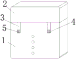
Fig. 1 is a front view of a bluetooth headset with wireless charging function according to embodiment 1;
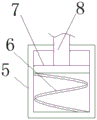
fig. 2 is a front cross-sectional view of a fixing tube of a bluetooth headset with wireless charging function according to embodiment 1;
fig. 3 is a front view of a rectangular card slot of a bluetooth headset with wireless charging function according to embodiment 1;
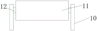
fig. 4 is a front view of a rotating roller of a bluetooth headset with wireless charging function according to embodiment 1;
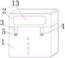
fig. 5 is a front view of a rough surface of a bluetooth headset with wireless charging function according to embodiment 2.
In the figure: 1-main body, 2-bin cover, 3-clamping strip, 4-rectangular groove, 5-fixed tube, 6-spring strip, 7-sliding plate, 8-connecting rod, 9-rectangular clamping groove, 10-bracket, 11-rotating roller, 12-rotating rod and 13-rough surface.
Detailed Description
In order to further describe the technical means and effects adopted by the present utility model for achieving the intended purpose, the following detailed description will refer to the specific implementation, structure, characteristics and effects according to the present utility model with reference to the accompanying drawings and preferred embodiments.
Example 1
Referring to fig. 1-4, a bluetooth headset with wireless function of charging, including main part 1, main part 1 top one side rotates and is connected with bin lid 2, inside bluetooth headset that is equipped with of main part 1, rectangle draw-in groove 9 has all been seted up to bin lid 2 bottom both sides, rectangle recess 4 has all been seted up at main part 1 top one side both ends, main part 1 is fixed with fixed pipe 5 in rectangle recess 4 department fixedly connected with, the inside sliding connection of fixed pipe 5 has sliding plate 7, sliding plate 7 bottom fixedly connected with spring strip 6, and spring strip 6 bottom and fixed pipe 5 inner wall fixed connection, sliding plate 7 top fixedly connected with connecting rod 8, and connecting rod 8 top runs through fixed pipe 5, connecting rod 8 top fixedly connected with draw-in bar 3, when the device closed bin lid 2, the inside sliding plate 7 of fixed pipe 5 rises under the elasticity effect of spring strip 6 self, sliding plate 7 top drives connecting rod 8 simultaneously rises, connecting rod 8 withstands card strip 3 constantly, card strip 3 top gets into rectangle draw-in groove 9 inside, the convenient block of device has been realized simultaneously, when the earphone bin falls, bin lid 2 upset can take place to interfere with card strip 3 self bin, even when falling device can not have been practical, and the device has been improved.
Wherein, equal fixedly connected with a plurality of support 10 in card strip 3 top both sides, the inside dwang 12 that is connected with of support 10 rotates through the pivot, the outside fixedly connected with rotor 11 of rotor 12, the distance between the rotor 11 of both sides equals the width of rectangle draw-in groove 9, a plurality of pilot lamp has been seted up to main part 1 outside one side, pilot lamp and main part 1 electric connection, when card strip 3 gets into rectangle draw-in groove 9 inside, rotor 11 gets into rectangle draw-in groove 9 inner wall and laminating with rectangle draw-in groove 9, rotor 11 self rotates simultaneously, utilize rolling friction to replace the sliding friction that can produce when card strip 3 gets into rectangle draw-in groove 9 inside originally, thereby reduce the resistance that rectangle draw-in groove 9 inner wall received, the wearing and tearing have been reduced.
Working principle: when the device closes the bin cover 2, the inside sliding plate 7 of fixed pipe 5 rises under the elasticity effect of spring strip 6 self, and the sliding plate 7 top drives connecting rod 8 simultaneously and rises, and the connecting rod 8 withstands card strip 3 constantly, and card strip 3 top gets into inside rectangular draw-in groove 9, has realized the convenient block of device simultaneously, and when the earphone bin was dropped, bin cover 2 upset can take place to interfere with card strip 3 self to guaranteed that the earphone bin even when dropping, bin cover 2 also can not automatic deflection, improved the practicality of device.
When the card strip 3 gets into inside the rectangle draw-in groove 9, the live-rollers 11 get into rectangle draw-in groove 9 inner wall and laminate with rectangle draw-in groove 9, and live-rollers 11 self rotates simultaneously, utilizes rolling friction to replace the sliding friction that can produce when the card strip 3 gets into inside the rectangle draw-in groove 9 originally to reduce the resistance that the rectangle draw-in groove 9 inner wall received, reduced wearing and tearing.
Example 2
Referring to fig. 5, in this embodiment, in order to increase the practicality of the device, the two sides of the cover 2 are provided with the rough surfaces 13, and when the cover 2 is opened, the rough surfaces 13 increase the friction between the cover 2 and the hands of the user, thereby improving the convenience when the cover 2 is opened.
Working principle: when the device closes the bin cover 2, the inside sliding plate 7 of fixed pipe 5 rises under the elasticity effect of spring strip 6 self, and the sliding plate 7 top drives connecting rod 8 simultaneously and rises, and the connecting rod 8 withstands card strip 3 constantly, and card strip 3 top gets into inside rectangular draw-in groove 9, has realized the convenient block of device simultaneously, and when the earphone bin was dropped, bin cover 2 upset can take place to interfere with card strip 3 self to guaranteed that the earphone bin even when dropping, bin cover 2 also can not automatic deflection, improved the practicality of device.
When the card strip 3 gets into inside the rectangle draw-in groove 9, the live-rollers 11 get into rectangle draw-in groove 9 inner wall and laminate with rectangle draw-in groove 9, and live-rollers 11 self rotates simultaneously, utilizes rolling friction to replace the sliding friction that can produce when the card strip 3 gets into inside the rectangle draw-in groove 9 originally to reduce the resistance that the rectangle draw-in groove 9 inner wall received, reduced wearing and tearing.
When the earphone cover 2 is opened, the rough surface 13 increases the friction between the cover 2 and the hand of the user, thereby improving the convenience of the device when the cover 2 is opened.
The present utility model is not limited to the above embodiments, but is capable of modification and variation in detail, and other modifications and variations can be made by those skilled in the art without departing from the scope of the present utility model.
Claims (6)
1. The utility model provides a bluetooth headset with wireless function of charging, includes main part (1), a serial communication port, main part (1) top one side is rotated and is connected with bin lid (2), and main part (1) inside bluetooth headset that is equipped with, rectangular draw-in groove (9) have all been seted up to bin lid (2) bottom both sides, rectangle recess (4) have all been seted up at main part (1) top one side both ends, main part (1) are fixed pipe (5) in rectangle recess (4) department fixedly connected with, the inside sliding connection of fixed pipe (5) has sliding plate (7), sliding plate (7) bottom fixedly connected with spring strip (6), and spring strip (6) bottom and fixed pipe (5) inner wall fixed connection, sliding plate (7) top fixedly connected with connecting rod (8), and connecting rod (8) top run through fixed pipe (5), connecting rod (8) top fixedly connected with card strip (3).
2. The bluetooth headset with the wireless charging function according to claim 1, wherein a plurality of brackets (10) are fixedly connected to two sides of the top end of the clamping strip (3).
3. The bluetooth headset with wireless charging function according to claim 2, wherein a rotating rod (12) is rotatably connected to the inside of the cradle (10) through a rotating shaft.
4. A bluetooth headset with wireless charging function according to claim 3, characterized in that the rotating rod (12) is fixedly connected with a rotating roller (11) outside, and the distance between the rotating rollers (11) at both sides is equal to the width of the rectangular clamping groove (9).
5. The bluetooth headset with wireless charging function according to claim 4, wherein a plurality of indicator lamps are arranged on one side of the outer portion of the main body (1), and the indicator lamps are electrically connected with the main body (1).
6. The Bluetooth headset with the wireless charging function according to claim 5, wherein rough surfaces (13) are formed on two sides of the bin cover (2).
Priority Applications (1)
| Application Number | Priority Date | Filing Date | Title |
|---|---|---|---|
| CN202221702943.5U CN219041941U (en) | 2022-07-04 | 2022-07-04 | Bluetooth headset with wireless function of charging |
Applications Claiming Priority (1)
| Application Number | Priority Date | Filing Date | Title |
|---|---|---|---|
| CN202221702943.5U CN219041941U (en) | 2022-07-04 | 2022-07-04 | Bluetooth headset with wireless function of charging |
Publications (1)
| Publication Number | Publication Date |
|---|---|
| CN219041941U true CN219041941U (en) | 2023-05-16 |
Family
ID=86291169
Family Applications (1)
| Application Number | Title | Priority Date | Filing Date |
|---|---|---|---|
| CN202221702943.5U Active CN219041941U (en) | 2022-07-04 | 2022-07-04 | Bluetooth headset with wireless function of charging |
Country Status (1)
| Country | Link |
|---|---|
| CN (1) | CN219041941U (en) |
-
2022
- 2022-07-04 CN CN202221702943.5U patent/CN219041941U/en active Active
Similar Documents
| Publication | Publication Date | Title |
|---|---|---|
| CN219041941U (en) | Bluetooth headset with wireless function of charging | |
| CN210247015U (en) | Earphone convenient to accomodate | |
| CN205092626U (en) | General charging seat of rail mounted | |
| CN209200704U (en) | A kind of electric wheelchair charging unit | |
| CN212969180U (en) | Angle-adjustable wireless charger convenient to charge | |
| CN208623396U (en) | A kind of desk wireless charging mounting structure | |
| CN213522333U (en) | Wireless Bluetooth mini-sports headset | |
| CN210629535U (en) | Portable wireless router | |
| CN211958142U (en) | Charging wire convenient to receive line | |
| CN212374547U (en) | D5X prevent that material area from hunch portable pinch roller | |
| CN209389753U (en) | A kind of novel porous cradle | |
| CN210806807U (en) | Ultrathin writing type wireless charger with sucker device | |
| CN209089187U (en) | A kind of bluetooth headset that can work as cell-phone cover charger baby | |
| CN212366871U (en) | Multifunctional mobile phone charger | |
| CN201364939Y (en) | Portable mobile phone charger | |
| CN215871778U (en) | Multi-purpose hangers formula wireless bluetooth headset | |
| CN219980454U (en) | Portable Bluetooth headset charger | |
| CN213990227U (en) | High-stability multi-coil charging device | |
| CN219138791U (en) | Matching device of fireproof door | |
| CN219812174U (en) | Portable control type mobile phone folding finger ring | |
| CN210780160U (en) | Portable treasured that charges | |
| CN207652066U (en) | A kind of collapsible wireless charger of more power selections | |
| CN219016941U (en) | Low-power-consumption Bluetooth mouse with high anti-interference capability | |
| CN213782931U (en) | Ultra-thin wireless charger | |
| CN212639498U (en) | Convenient treasured that charges is accomodate to charging wire |
Legal Events
| Date | Code | Title | Description |
|---|---|---|---|
| GR01 | Patent grant | ||
| GR01 | Patent grant |