CN219039121U - Wind generating set circuit check out test set - Google Patents
Wind generating set circuit check out test set Download PDFInfo
- Publication number
- CN219039121U CN219039121U CN202222914423.7U CN202222914423U CN219039121U CN 219039121 U CN219039121 U CN 219039121U CN 202222914423 U CN202222914423 U CN 202222914423U CN 219039121 U CN219039121 U CN 219039121U
- Authority
- CN
- China
- Prior art keywords
- fixedly connected
- pen
- groove
- main body
- detection
- Prior art date
- Legal status (The legal status is an assumption and is not a legal conclusion. Google has not performed a legal analysis and makes no representation as to the accuracy of the status listed.)
- Active
Links
Images


Classifications
-
- Y—GENERAL TAGGING OF NEW TECHNOLOGICAL DEVELOPMENTS; GENERAL TAGGING OF CROSS-SECTIONAL TECHNOLOGIES SPANNING OVER SEVERAL SECTIONS OF THE IPC; TECHNICAL SUBJECTS COVERED BY FORMER USPC CROSS-REFERENCE ART COLLECTIONS [XRACs] AND DIGESTS
- Y02—TECHNOLOGIES OR APPLICATIONS FOR MITIGATION OR ADAPTATION AGAINST CLIMATE CHANGE
- Y02E—REDUCTION OF GREENHOUSE GAS [GHG] EMISSIONS, RELATED TO ENERGY GENERATION, TRANSMISSION OR DISTRIBUTION
- Y02E10/00—Energy generation through renewable energy sources
- Y02E10/70—Wind energy
- Y02E10/72—Wind turbines with rotation axis in wind direction
Landscapes
- Testing Or Calibration Of Command Recording Devices (AREA)
Abstract
The utility model discloses a circuit detection device of a wind generating set, which relates to the technical field of circuit detection and comprises a device main body, wherein a wire releasing groove is formed in the device main body, a connecting block is fixedly connected in the wire releasing groove, a rotating shaft is fixedly connected to the outer side of the connecting block, a cover plate is rotatably connected to the outer side of the rotating shaft, pen releasing grooves are formed in the left end and the right end of the device main body, a clamping block is fixedly connected in the pen releasing grooves, a detection pen is movably connected in the pen releasing grooves, a connecting wire is fixedly connected to the lower end of the detection pen, a plug is fixedly connected to the lower end of the connecting wire, a through groove is formed in the device main body, when detection is completed, the connecting wire is rolled up and placed in the wire collecting groove, then the connecting wire at the bottom end of the detection pen penetrates through the through groove, then the detection pen is placed in the pen releasing groove and is fixed by the clamping block, and then the cover plate is closed.
Description
Technical Field
The utility model relates to the technical field of circuit detection, in particular to wind generating set circuit detection equipment.
Background
Wind power generation is greatly popularized worldwide because wind is clean energy, the phenomenon of wire aging and wire fusing is inevitably encountered in the power generation process, and maintenance personnel are required to hold special circuit detection equipment to sequentially check a damaged circuit in the maintenance process.
Because wind generating set needs to erect in higher place from ground, maintenance personnel need only overhaul it after the climbing, and present check out test set has very long connecting wire and test pen and separates with the main part usually, because of it does not possess the effect of accomodating, just takes place the condition of losing easily, influences the efficiency of maintenance.
Disclosure of Invention
The utility model aims to provide wind generating set circuit detection equipment so as to solve the problem that the wind generating set circuit detection equipment cannot be stored in the background technology.
In order to achieve the above purpose, the present utility model provides the following technical solutions: the utility model provides a wind generating set circuit check out test set, includes the equipment main part, the inside pay off groove of having seted up of equipment main part, the inside fixedly connected with connecting block of pay off groove, connecting block outside fixedly connected with axis of rotation, the axis of rotation outside rotates and is connected with the apron, the pen groove has all been seted up at both ends about the equipment main part, the inside fixedly connected with fixture block of pen groove, the inside swing joint of pen groove has the detection pen, detection pen lower extreme fixedly connected with connecting wire, connecting wire lower extreme fixedly connected with plug, logical groove has been seted up to the inside of equipment main part.
Further, the display screen is installed inside the equipment main body, the adjusting knob is connected inside the equipment main body in a rotating mode, the connecting port is fixedly connected inside the equipment main body, the state of the circuit is digitally displayed, and whether the circuit is damaged or not is conveniently judged.
Further, equipment main part rear end fixedly connected with fixed frame, fixed frame inside fixedly connected with magnet is convenient for adsorb equipment main part on the iron shell of the detected object when detecting, conveniently observes the detection data.
Further, the fixed frame is connected with the rotating column in an internal rotating mode, the supporting plate is fixedly connected to the outer side of the rotating column, and when no iron product exists on the outer side of the tested device, the supporting plate can be opened to be placed with two hands, and danger caused by single-hand operation is avoided.
Further, the outside fixedly connected with rubber sleeve of detection pen, detection pen upper end fixedly connected with probe rod, installation insulation sleeve makes the contact position insulating, avoids detection pen to appear the condition of electric leakage because of ageing.
Further, the upper end of the probe rod is fixedly connected with a ball head, the outer side of the ball head is movably connected with a probe, and the angle of the probe is convenient to rotate so as to reach a position where the probe rod cannot be reached.
Compared with the prior art, the utility model has the beneficial effects that: this wind generating set circuit check out test set, when the detection is accomplished, take off the plug to roll up the connecting wire and place inside the receipts wire casing, then pass the connecting wire of detecting the pen bottom in the inside logical groove of equipment main part, place the detecting pen in putting the inslot portion and make it fixed by the fixture block, pass through the axis of rotation with the apron again and rotate and close, the annex that equipment has is also accomodate inside the main part this moment, avoids taking place the phenomenon of losing, and portable.
Drawings
FIG. 1 is a schematic diagram of a split structure of the present utility model;
FIG. 2 is a schematic perspective view of the present utility model;
FIG. 3 is a schematic view of the back structure of the present utility model
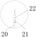
Fig. 4 is an enlarged schematic view of fig. 1 at a in accordance with the present utility model.
In the figure: 1. an apparatus main body; 2. wire releasing grooves; 3. a connecting block; 4. a rotating shaft; 5. a cover plate; 6. a pen placing groove; 7. a clamping block; 8. a detection pen; 9. a connecting wire; 10. a plug; 11. a through groove; 12. a display screen; 13. an adjustment knob; 14. a connection port; 15. a fixed frame; 16. a magnet; 17. rotating the column; 18. a support plate; 19. a rubber sleeve; 20. a probe rod; 21. ball head; 22. and (3) a probe.
Detailed Description
The following description of the embodiments of the present utility model will be made clearly and completely with reference to the accompanying drawings, in which it is apparent that the embodiments described are only some embodiments of the present utility model, but not all embodiments. All other embodiments, which can be made by those skilled in the art based on the embodiments of the utility model without making any inventive effort, are intended to be within the scope of the utility model.
Referring to fig. 1-4, the present utility model provides a technical solution: the utility model provides a wind generating set circuit check out test set, includes equipment main part 1, the inside wire groove 2 of having seted up of equipment main part 1, wire groove 2 inside fixedly connected with connecting block 3, connecting block 3 outside fixedly connected with axis of rotation 4, axis of rotation 4 outside rotation is connected with apron 5, both ends have all been seted up about equipment main part 1 put a groove 6, put 6 inside fixedly connected with fixture block 7 in a groove, put 6 inside swing joint in a groove 8 and detect a, detect 8 lower extreme fixedly connected with connecting wire 9, 9 lower extreme fixedly connected with plug 10 of connecting wire, logical groove 11 has been seted up to equipment main part 1 inside.
The display screen 12 is arranged in the equipment main body 1, the adjusting knob 13 is connected to the inside rotation of the equipment main body 1, the connecting port 14 is fixedly connected to the inside of the equipment main body 1, the state of a circuit is digitally displayed, whether the circuit is damaged or not is conveniently judged, the fixing frame 15 is fixedly connected to the rear end of the equipment main body 1, the magnet 16 is fixedly connected to the inside of the fixing frame 15, the equipment main body 1 is conveniently adsorbed on an iron shell of a detected object during detection, and detection data is conveniently observed.
Simultaneously, fixed frame 15 inside rotates and is connected with the rotation post 17, rotation post 17 outside fixedly connected with backup pad 18, when the device outside of being surveyed does not have ironwork, can open the backup pad 18 and place liberation both hands, avoid the one-hand operation to produce danger, detection pen 8 outside fixedly connected with rubber sleeve 19, detection pen 8 upper end fixedly connected with probe rod 20, installation rubber sleeve 19 makes the contact position insulating, avoids detection pen 8 to appear the condition of electric leakage because of ageing.
In addition, the upper end of the probe rod 20 is fixedly connected with a ball head 21, and the outer side of the ball head 21 is movably connected with a probe 22, so that the probe 22 can be conveniently rotated to reach a position where the probe rod 20 cannot be reached.
Working principle: when the detection device is used, firstly, the cover plate 5 is outwards rotated to open and remove the internal connecting wire 9 through the rotating shaft 4 on the connecting block 3, then the detection pens 8 in the pen holding grooves 6 on two sides are taken out, then the plug 10 at one end of the connecting wire 9 is inserted into the connecting port 14, then the device main body 1 is adsorbed on the iron shell of the device to be detected through the magnet 16 in the fixing frame 15, or the supporting plate 18 is outwards rotated and unfolded through the rotating column 17 and then placed at a position suitable for observation, then the device is adjusted to a proper position through the adjusting knob 13, then the rubber sleeve 19 at the outer side of the detection pen 8 is held by hands and then pressed on the surface of the circuit to be detected, the damage condition of the circuit is judged through the data displayed by the display screen 12, when the position which is not easy to touch is detected, the probe 22 at the outer side of the ball head 21 can be adjusted, an included angle is formed between the probe 20 and the probe rod 20, the plug 10 is conveniently detected, the connecting wire 9 is coiled and placed in the paying-off groove 2, then the connecting wire 9 at the bottom of the detection pen 8 passes through the through groove 11 in the device main body 1, then the detecting groove 8 is placed in the inner side of the device main body 1, then the detecting groove 8 is placed in the groove 6 and the position is also placed in the pen holding groove 7, and the rotating groove is fixed in the rotating groove through the rotating groove 4, and the pen is convenient to be carried by the pen holding device, and the pen holding device is prevented from losing the pen holding device, and the pen holding device is convenient to be held by the portable and the pen holding device.
Although embodiments of the present utility model have been shown and described, it will be understood by those skilled in the art that various changes, modifications, substitutions and alterations can be made therein without departing from the principles and spirit of the utility model, the scope of which is defined in the appended claims and their equivalents.
Claims (6)
1. Wind generating set circuit check out test set, including equipment main part (1), its characterized in that: the utility model is characterized in that the device main body (1) is internally provided with a wire releasing groove (2), the inside of the wire releasing groove (2) is fixedly connected with a connecting block (3), the outside of the connecting block (3) is fixedly connected with a rotating shaft (4), the outside of the rotating shaft (4) is rotationally connected with a cover plate (5), the left end and the right end of the device main body (1) are respectively provided with a pen releasing groove (6), put inside fixedly connected with fixture block (7) of a groove (6), put inside swing joint in a groove (6) and detect pen (8), detect pen (8) lower extreme fixedly connected with connecting wire (9), connecting wire (9) lower extreme fixedly connected with plug (10), logical groove (11) have been seted up to equipment main part (1) inside.
2. A wind turbine generator system circuit testing device according to claim 1, wherein: the device is characterized in that a display screen (12) is arranged in the device body (1), an adjusting knob (13) is rotatably connected to the inside of the device body (1), and a connecting port (14) is fixedly connected to the inside of the device body (1).
3. A wind turbine generator system circuit testing device according to claim 1, wherein: the device is characterized in that the rear end of the device main body (1) is fixedly connected with a fixed frame (15), and a magnet (16) is fixedly connected inside the fixed frame (15).
4. A wind turbine generator system circuit testing apparatus according to claim 3, wherein: the inside rotation of fixed frame (15) is connected with rotation post (17), rotation post (17) outside fixedly connected with backup pad (18).
5. A wind turbine generator system circuit testing device according to claim 1, wherein: the outside fixedly connected with rubber sleeve (19) of detection pen (8), detection pen (8) upper end fixedly connected with probe rod (20).
6. The wind turbine generator system circuit testing apparatus of claim 5, wherein: the upper end of the probe rod (20) is fixedly connected with a ball head (21), and the outer side of the ball head (21) is movably connected with a probe (22).
Priority Applications (1)
| Application Number | Priority Date | Filing Date | Title |
|---|---|---|---|
| CN202222914423.7U CN219039121U (en) | 2022-11-03 | 2022-11-03 | Wind generating set circuit check out test set |
Applications Claiming Priority (1)
| Application Number | Priority Date | Filing Date | Title |
|---|---|---|---|
| CN202222914423.7U CN219039121U (en) | 2022-11-03 | 2022-11-03 | Wind generating set circuit check out test set |
Publications (1)
| Publication Number | Publication Date |
|---|---|
| CN219039121U true CN219039121U (en) | 2023-05-16 |
Family
ID=86272610
Family Applications (1)
| Application Number | Title | Priority Date | Filing Date |
|---|---|---|---|
| CN202222914423.7U Active CN219039121U (en) | 2022-11-03 | 2022-11-03 | Wind generating set circuit check out test set |
Country Status (1)
| Country | Link |
|---|---|
| CN (1) | CN219039121U (en) |
-
2022
- 2022-11-03 CN CN202222914423.7U patent/CN219039121U/en active Active
Similar Documents
| Publication | Publication Date | Title |
|---|---|---|
| CN102023273A (en) | Portable domestic photo voltaic power station performance tester | |
| CN207684666U (en) | A kind of pole tower ground resistance measurement take-up and pay-off device | |
| CN219039121U (en) | Wind generating set circuit check out test set | |
| CN217213088U (en) | Electric leakage detection device for power equipment | |
| CN213745875U (en) | Portable water flow velocity measuring device for water conservancy detection | |
| CN214041272U (en) | Portable nondestructive test equipment | |
| CN213580748U (en) | On-site wall heat transfer coefficient detector with high detection sensitivity | |
| CN206244202U (en) | High speed payout device | |
| CN207601227U (en) | A kind of insualtor detector for acquiring spark image | |
| CN218412752U (en) | Electricity inspection tester | |
| CN218331651U (en) | Portable detection device for electric power detection and maintenance | |
| CN215116401U (en) | Outdoor power equipment detection device | |
| CN213337868U (en) | Portable power cable's fault tester | |
| CN219039341U (en) | Electric energy metering equipment calibration device without load | |
| CN218524625U (en) | Prevent submerged conductivity detection device of intaking | |
| CN217689257U (en) | Lightning protection downlead insulating layer check out test set | |
| CN216083055U (en) | Electrical equipment detection device with circuit protection structure | |
| CN217332385U (en) | Sodium ion concentration analysis measuring equipment | |
| CN219224934U (en) | Test power meter | |
| CN213956709U (en) | Municipal bridge state detection device | |
| CN220231877U (en) | Portable electric energy quality analysis monitor | |
| CN212254189U (en) | Noise detection device for environment detection | |
| CN219641823U (en) | Ground resistance check out test set | |
| CN210222132U (en) | Semiconductor static testing device | |
| CN204597248U (en) | Power distribution cabinet |
Legal Events
| Date | Code | Title | Description |
|---|---|---|---|
| GR01 | Patent grant | ||
| GR01 | Patent grant |