CN219036781U - Air supply device - Google Patents
Air supply device Download PDFInfo
- Publication number
- CN219036781U CN219036781U CN202222750576.2U CN202222750576U CN219036781U CN 219036781 U CN219036781 U CN 219036781U CN 202222750576 U CN202222750576 U CN 202222750576U CN 219036781 U CN219036781 U CN 219036781U
- Authority
- CN
- China
- Prior art keywords
- humidifying
- fog
- air supply
- mist
- supply device
- Prior art date
- Legal status (The legal status is an assumption and is not a legal conclusion. Google has not performed a legal analysis and makes no representation as to the accuracy of the status listed.)
- Active
Links
Images


Landscapes
- Air Humidification (AREA)
Abstract
The application belongs to domestic appliance technical field, concretely relates to air supply arrangement aims at solving the technical problem that air supply arrangement exists among the correlation technique that the fog area is little, and the humidification effect is poor to at least a certain extent. The air supply device comprises a shell, a water-air assembly and a fog channel, wherein the output end of the water-air assembly can output water fog, the fog channel is arranged in the shell along the height direction of the shell, the end part of the fog channel is provided with a fog inlet communicated with the output end of the water-air assembly, the side part of the fog channel is provided with a humidifying inlet, and the cross-sectional area of the fog channel is sequentially reduced along the direction away from the fog inlet. The mist outlet area of the air supply device can be improved, the humidifying effect of the air supply device is improved, and user experience is improved.
Description
Technical Field
The application belongs to the technical field of household appliances, and particularly relates to an air supply device.
Background
The warm air blower is one kind of air supply device, and the warm air blower can supply warm air, can be used for the heating dehumidification of various types of workshops, also can be used as the room heater of family. The working principle is as follows: under the power action of the ventilator, air enters the unit from the air suction inlet, flows out of the unit from the air blowing inlet after being heated in the unit to form warm air, and is sent to a heating space to form indoor air circulation, so that heating of an indoor environment is realized.
In order to improve the comfort level of the heating space, the air supply device is configured with a humidifying function, namely, a humidifying port is formed in the unit so as to blow out water mist.
In the related art, the humidification mouth is arranged at the top or the bottom of the product more, has the technical problem that the mist outlet area is small, and the humidification effect is poor.
Disclosure of Invention
In order to solve the technical problem, the application provides an air supply device, and aims to solve the technical problems of small fog outlet area and poor humidifying effect of the air supply device in the related technology to at least a certain extent.
The technical scheme of the application is as follows:
an air moving device, the air moving device comprising:
a housing;
the output end of the water-gas assembly can output water mist;
the fog way is arranged in the shell along the height direction of the shell, the end part of the fog way is provided with a fog inlet communicated with the output end of the water-air assembly, the side part of the fog way is provided with a humidifying port, and the cross-sectional area of the fog way is sequentially reduced along the direction away from the fog inlet.
The utility model provides an air supply arrangement, because the output of aqueous vapor subassembly can export the water smoke, the output of aqueous vapor subassembly and the fog mouth intercommunication that advances of fog way, the lateral part that the fog was said is provided with the humidification mouth, like this, the water smoke that the output of aqueous vapor subassembly was said, the fog mouth that advances that the accessible fog was said enters into the fog and says to export through the humidification mouth, in order to blow out water smoke, make air supply arrangement have the humidification function.
Because the humidification mouth sets up in the lateral part of fog way, the fog way sets up along the direction of height of casing promptly, can make the humidification mouth of fog way have bigger output area like this to improve the output space of humidification mouth, improve air supply arrangement's play fog area is little, improves air supply arrangement's humidification effect, in order to improve user experience.
In addition, because the cross-sectional area of fog way is along keeping away from advance fog mouth's direction reduces in proper order, can make the fog way form one along the direction that is away from into fog mouth and reduce in proper order the cavity like this, can make with the air current velocity of the nearly humidification mouth of the output of aqueous vapor subassembly reduce with this cavity, the far away humidification mouth velocity of flow promotes, and the play fog velocity of flow of guaranteeing whole humidification mouth is even from this to promote product humidification volume, humidification more even and difficult ponding, play fog effect better.
In some embodiments, the side of the shell is provided with a humidifying part, two sides of the humidifying part are connected with the shell through humidifying plates, and at least one humidifying plate is provided with the humidifying port.
In some embodiments, the humidifying ports are provided on the humidifying plates located on both sides of the humidifying part. I.e. the mist can be led out from the humidifying ports at two sides to form two mist flows, thereby improving the mist outlet efficiency.
In some embodiments, the side of the fog channel facing the humidifying part is open, and two sides of the opening of the fog channel are respectively connected to the humidifying plates on the same side.
In some embodiments, the distance from the side of the fog channel facing away from the humidifying part to the humidifying part sequentially decreases in a direction away from the fog inlet.
In some embodiments, the distance from the side of the fog channel facing away from the humidification portion to the humidification portion is inversely proportional to the height of the fog channel.
In some embodiments, a grille is disposed within the humidification port.
In some embodiments, the air supply device further comprises:
the lamp body mounting piece is arranged in the fog channel, the lamp body mounting piece is provided with a lamp groove, an opening of the lamp groove faces the humidifying part, and the opening of the lamp groove is sealed through the humidifying part;
the luminous piece is arranged in the lamp groove. The luminous piece can form patterns at the humidifying port, so that the aesthetic feeling of the air supply device in use is improved.
In some embodiments, the side part of the lamp slot is provided with a light guide member, and the light guide member and the humidifying port are correspondingly arranged so as to enable the light emitted by the light emitting member to be emitted from the corresponding humidifying port through the guide of the light guide member. Under the irradiation of lamplight, the mist blown out from the humidifying port can form different irradiation effects through the light guiding effect of the light guiding piece, so that the aesthetic feeling of the air supply device during use is further improved.
In some embodiments, the water vapor assembly is disposed at a bottom of the housing and the mist inlet is disposed at a bottom of the mist channel.
In some embodiments, the air moving device is a fan heater, a stand fan, or a humidifier.
Drawings
In order to more clearly illustrate the technical solutions of the embodiments of the present utility model, the drawings required for the description of the embodiments will be briefly described below, and it is apparent that the drawings in the following description are only some embodiments of the present utility model, and other drawings may be obtained according to these drawings without inventive effort for a person skilled in the art.
In the accompanying drawings:
fig. 1 is a schematic structural diagram of an air supply device according to an embodiment of the present application;
FIG. 2 is a schematic front view of FIG. 1;
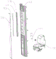
FIG. 3 is an internal explosion schematic of FIG. 1;
FIG. 4 is a schematic cross-sectional view of the fog track of FIG. 1;
fig. 5 is a schematic structural assembly diagram of a lamp body mounting member and a light emitting member according to an embodiment of the present application.
Reference numerals:
the device comprises a shell, a humidifying port, a control area, a humidifying part, a humidifying plate and a humidifying plate, wherein the shell, the humidifying port, the control area, the humidifying part and the humidifying plate are respectively provided with a shell, a humidifying opening, a humidifying port, a control area, a humidifying part and a humidifying plate;
a water-air assembly-200;
mist channel-300;
a base-400;
connecting the pipe to 500;
a lamp body mounting part-600, a lamp groove-601;
light-emitting member-700.
Detailed Description
The following description of the embodiments of the present application will be made clearly and fully with reference to the accompanying drawings, in which it is evident that the embodiments described are only some, but not all, of the embodiments of the present application. All other embodiments, which can be made by one of ordinary skill in the art based on the embodiments herein without making any inventive effort, are intended to be within the scope of the present application.
It should be noted that all the directional indicators in the embodiments of the present application are only used to explain the relative positional relationship, movement conditions, etc. between the components in a specific posture, and if the specific posture is changed, the directional indicators are correspondingly changed.
The following disclosure provides many different embodiments, or examples, for implementing different structures of the application. In order to simplify the disclosure of the present application, the components and arrangements of specific examples are described below. Of course, they are merely examples and are not intended to limit the present application. Furthermore, the present application may repeat reference numerals and/or letters in the various examples, which are for the purpose of brevity and clarity, and which do not in themselves indicate the relationship between the various embodiments and/or arrangements discussed. In addition, the present application provides examples of various specific processes and materials, but one of ordinary skill in the art may recognize the application of other processes and/or the use of other materials.
The present application is described below with reference to specific embodiments in conjunction with the accompanying drawings:
in the related art, the humidifying ports of the air supply device are arranged at the top or bottom of the unit, so that the technical problems of small mist outlet area and poor humidifying effect exist.
Based on the technical problems, the embodiment of the application provides an air supply device, and aims to solve the technical problems of small fog outlet area and poor humidifying effect of the air supply device in the related technology to at least a certain extent.
Fig. 1 is a schematic structural diagram of an air supply device according to an embodiment of the present application, fig. 2 is a front view of fig. 1, fig. 3 is an internal explosion of fig. 1, and fig. 4 is a schematic sectional structural diagram of a fog path in fig. 1. Referring to fig. 1-4, the embodiment of the application provides an air supply device, the air supply device includes a housing 100, a water-air assembly 200 and a fog channel 300, wherein the housing 100 is a carrier of a whole unit, a base 400 for sitting on a working surface is provided at the bottom of the housing 100, a control button can be provided on the surface of the housing 100, an output end of the water-air assembly 200 can output water fog, the fog channel 300 is disposed in the housing 100 along the height direction of the housing 100, an end of the fog channel 300 is provided with a fog inlet communicated with the output end of the water-air assembly 200, a humidifying port 101 is provided at the side of the fog channel 300, and the cross-sectional area of the fog channel 300 is sequentially reduced along the direction far away from the fog inlet.
According to the air supply device provided by the embodiment of the application, water mist can be output from the output end of the water-air assembly 200, the output end of the water-air assembly 200 is communicated with the mist inlet of the mist channel 300, the humidifying port 101 is arranged on the side portion of the mist channel 300, and therefore the water mist output from the output end of the water-air assembly 200 can enter the mist channel 300 through the mist inlet of the mist channel 300 and is output through the humidifying port 101 so as to blow out the water mist, and the air supply device has a humidifying function.
Because the humidification port 101 is disposed at the side of the fog path 300, that is, the fog path 300 is disposed along the height direction of the housing 100, the humidification port 101 of the fog path 300 has a larger output area, so as to improve the output space of the humidification port 101, improve the mist outlet area of the air supply device, and improve the humidification effect of the air supply device, thereby improving the user experience.
In addition, because the cross-sectional area of the fog channel 300 is sequentially reduced along the direction away from the fog inlet, the fog channel 300 can form a cavity which is sequentially reduced along the direction away from the fog inlet, the airflow velocity of the humidifying port 101 close to the output end of the water-air assembly 200 can be reduced by using the cavity, the flow velocity of the humidifying port 101 far away from the output end is improved, and therefore the uniform fog outlet flow velocity of the whole humidifying port 101 is ensured, the humidifying capacity of a product is improved, the humidification is more uniform, water accumulation is difficult, and the fog outlet effect is better.
Referring to fig. 1, in the embodiment of the present application, an on-surface manipulation area 102 is disposed at the top of the housing 100, and a manipulation button is disposed on the manipulation area 102. Of course, the manipulation area 102 may be disposed at other locations, which is not limited herein.
The humidifying port 101 of the embodiment of the application can be in a long and narrow strip shape, and a grid can be arranged in the humidifying port 101 so as to improve the uniformity of mist extraction.
Further, referring to fig. 1 and 4, the side portion of the housing 100 in the embodiment of the present application may be provided with a humidifying portion 103, where the humidifying portion 103 protrudes out of the side portion of the housing 100, and two sides of the humidifying portion 103 and the side portion of the housing 100 are connected by humidifying plates 104, and each humidifying plate 104 is provided with the humidifying port 101. That is, two humidification ports 101 are provided on two sides of the humidification portion 103, and thus mist can be led out from the humidification ports 101 on two sides to form two mist streams and blow in opposite directions, so that mist outlet efficiency and mist outlet effect are improved.
Of course, in other embodiments, the humidifying port 101 may be provided only on one side of the humidifying portion 103, and even the humidifying portion 103 may be provided with the humidifying port 101, which is not limited thereto.
Specifically, the distance between the humidifying portion 103 and the side portion of the housing 100 in the embodiment of the present application may be not greater than 30mm, and the width of the humidifying port 101 may be 2-10mm, and the aspect ratio thereof may be not greater than 1:10, and specifically may be adjusted accordingly according to the actual size, which is not limited herein.
In this embodiment, the mist inlet is preferably disposed at an end of the mist channel 300, the entire mist channel 300 may be approximately arc-shaped, the side surface of the mist channel 300 facing the humidifying portion 103 is open, and two sides of the opening of the mist channel 300 are respectively connected to the humidifying plates 104 on the same side. According to the embodiment of the application, the distance from one side of the fog channel 300, which is opposite to the humidifying part 103, to the humidifying part 103 is sequentially reduced along the direction away from the fog inlet, so that the fog channel 300 forms a cavity with a large bottom and a small top, the distance from one side of the fog channel 300, which is opposite to the humidifying part 103, to the humidifying part 103 can be in inverse proportion to the corresponding height, namely, the higher the height of a certain point of the fog channel 300 is, the larger the distance from one side of the fog channel 300, which is opposite to the humidifying part 103, is, the airflow velocity of the humidifying port 101, which is close to the output end of the water-air assembly 200, is reduced by the cavity, and the airflow velocity of the humidifying port 101 with a long distance is improved, so that the mist outlet flow velocity of the whole humidifying port 101 is uniform is ensured.
Preferably, the water-air assembly 200 of the embodiment of the present application is disposed at the bottom of the housing 100, the mist inlet is disposed at the bottom of the mist channel 300, and the output end of the water-air assembly can be communicated with the mist inlet of the mist channel 300 through the connecting pipe 500.
Referring to fig. 3, in the embodiment of the present application, the water-air assembly 200 may be disposed at the bottom of the housing 100, so that the center of gravity of the air supply device is concentrated on the base 400 of the air supply device, and the stability of the air supply device during use is improved.
Of course, in other embodiments, the water vapor assembly 200 may be disposed at the top of the housing 100, and correspondingly, the mist inlet is also disposed at the top of the mist duct 300; alternatively, the water vapor assembly 200 is integrated on the back of the housing 100, which is not described herein.
The water-air assembly 200 of the present embodiment may include a water tank and a water outlet fan, where the water flowing out of the water tank is atomized by the water outlet fan and is delivered to the mist channel 300 through the connecting pipe 500, which is not described herein.
Fig. 5 is a schematic structural assembly diagram of a lamp body mounting member and a light emitting member according to an embodiment of the present application. Referring to fig. 4 and 5, the air supply device according to the embodiment of the present application may further include a lamp body mounting member 600 and a light emitting member 700, where the lamp body mounting member 600 is disposed in the fog duct 300, the lamp body mounting member 600 is provided with a lamp slot 601, an opening of the lamp slot 601 faces the air outlet side 101, and the opening of the lamp slot 601 is sealed by the humidifying portion 103, and the light emitting member 700 is disposed in the lamp slot 601. The light emitting member 700 may be an LED light bar, and when the LED light bar shines on the sprayed mist, the fluttering mist may form various pattern effects such as dynamic simulated flame with the lamplight, so as to increase the aesthetic feeling of the air supply device when in use.
Specifically, the lamp groove 601 of the lamp body mounting member 600 may be V-shaped or arc-shaped, two sides of the lamp groove 601 may be clamped on the inner side of the humidifying part, the lamp groove 601 and the humidifying part 103 form a space for accommodating the light emitting member 700, and the humidifying port 101 on the humidifying part 103 may be disposed on two sides of the lamp body mounting member 600.
The side portion of the lamp groove in this embodiment is further provided with a light guide member, and the light guide member and the humidifying port 101 are correspondingly arranged, so that light rays emitted by the light emitting member 700 are emitted from the corresponding humidifying port 101 through the guiding of the light guide member. Under the irradiation of lamplight, and under the light guiding effect of the light guiding piece, the mist blown out of the humidifying port 101 can form different irradiation effects so as to further increase the aesthetic feeling of the air supply device during use.
In this embodiment, the position of the sidewall of the lamp groove 601 corresponding to the humidifying hole may be set to be a light guiding material, that is, the light guiding member is integrated on the lamp body mounting member 600. The light emitting member 700 may be a colored light emitting body, for example, the light emitting member 700 may emit red light, blue light, green light, etc., so that the mist discharged from the humidifying outlet 101 is more obvious under the condition of colored light. In addition, when the light emitting member 700 emits red or orange light, mist discharged from the humidifying port 101 exhibits a flame effect under the effect of the red light, thereby improving a user's visual sense.
According to the embodiment of the application, the luminous piece 700 is arranged in the fog channel 300, the luminous piece 700 emits light to the adjacent humidifying port 101, the light of the luminous piece 700 can be emitted to fog discharged from the humidifying port 101, a dynamic effect is formed on the fog, the fog circulation can be obviously seen, and the observation of the fog state is facilitated.
In addition, the humidifying part 103 and the lamp body mounting member 600 of the embodiment of the application can form a lamp cover after being connected to protect the light emitting member 700 and prevent dust and mist from entering the lamp groove, so that the service life of the light emitting member 700 is prolonged. The humidification portion 103 can be the opaque material, can avoid the strong light in the luminous element 700 to penetrate through humidification portion 103, in addition, the setting of leaded light spare can prevent the light direct irradiation humidification mouth 101 department of luminous element 700 light water smoke, and the light of water smoke reflection is comparatively dazzling, avoids causing the uncomfortable phenomenon of user to take place.
Further, in the embodiment of the present application, at least one of the surface of the lampshade facing the light emitting member 700 and the surface facing away from the light emitting member 700 has a rough structure or a coating. Because the application scene of the air supply device is wider, the air supply device can work at night, and the luminous piece 700 can be glaring at night, the lampshade can be frosted, so that at least one of the surfaces of the lampshade facing the luminous piece 700 and deviating from the luminous piece 700 is provided with a rough structure, light emitted by the luminous piece can be scattered, and the lamplight is softer and not glaring.
Of course, the spraying may be performed on at least one of the surfaces of the lampshade facing the light emitting member 700 and facing away from the light emitting member 700, so that a coating is provided on at least one of the surfaces of the lampshade facing the light emitting member 700 and facing away from the light emitting member 700, after the transmittance is changed, the color of the light can be changed through the coatings with different colors, the color of the light emitted by the light emitting member can be changed while the light is dimmed, the effect of soft light is achieved, and the attractive appearance is also achieved.
The air supply arrangement of this application embodiment can be the electric fan heater, and the warm braw that the electric fan heater generated can mix with the fog that humidification mouth 101 led out to output warm and moist air current, with carrying to required heating space, improvement user experience. In other embodiments, the air supply device may also be a vertical fan to output a humid air stream. Of course, the air blower may have only a humidifying function, that is, the air blower may be a humidifier, which is not limited herein.
In the present application, unless explicitly specified and limited otherwise, the terms "coupled," "secured," and the like are to be construed broadly, and for example, "secured" may be either permanently attached or removably attached, or integrally formed; can be mechanically or electrically connected; either directly or indirectly, through intermediaries, or both, may be in communication with each other or in interaction with each other, unless expressly defined otherwise. The specific meaning of the terms in this application will be understood by those of ordinary skill in the art as the case may be.
In the description of the present application, it should be understood that the terms "center," "longitudinal," "transverse," "length," "width," "thickness," "upper," "lower," "front," "rear," "left," "right," "vertical," "horizontal," "top," "bottom," "inner," "outer," "clockwise," "counterclockwise," etc. indicate or are based on the orientation or positional relationship shown in the drawings, merely for convenience of description and to simplify the description, and do not indicate or imply that the devices or elements referred to must have a specific orientation, be configured and operated in a specific orientation, and thus should not be construed as limiting the present application.
In addition, descriptions such as those related to "first," "second," and the like, are provided for descriptive purposes only and are not to be construed as indicating or implying relative importance or implicitly indicating the number of technical features indicated in this application. Thus, a feature defining "a first" or "a second" may explicitly or implicitly include at least one such feature. In addition, the technical solutions of the embodiments may be combined with each other, but it is necessary to base that the technical solutions can be realized by those skilled in the art, and when the technical solutions are contradictory or cannot be realized, the combination of the technical solutions should be regarded as not exist and not within the protection scope of the present application.
In the description of the present application, unless explicitly stated and limited otherwise, a first feature "above" or "below" a second feature may include both the first and second features being in direct contact, or may include both the first and second features not being in direct contact but being in contact by another feature therebetween. Moreover, a first feature being "above," "over" and "on" a second feature includes the first feature being directly above and obliquely above the second feature, or simply indicating that the first feature is higher in level than the second feature. The first feature being "under", "below" and "beneath" the second feature includes the first feature being directly under and obliquely below the second feature, or simply means that the first feature is less level than the second feature.
In the description of the present specification, a description referring to terms "one embodiment," "some embodiments," "examples," "specific examples," or "some examples," etc., means that a particular feature, structure, material, or characteristic described in connection with the embodiment or example is included in at least one embodiment or example of the present application. In this specification, schematic representations of the above terms are not necessarily directed to the same embodiment or example. Furthermore, the particular features, structures, materials, or characteristics described may be combined in any suitable manner in any one or more embodiments or examples. Further, one skilled in the art can engage and combine the different embodiments or examples described in this specification.
While the preferred embodiments of the present application have been described, additional variations and modifications in those embodiments may occur to those skilled in the art once they learn of the basic inventive concepts. It is therefore intended that the following claims be interpreted as including the preferred embodiments and all such alterations and modifications as fall within the scope of the application.
It will be apparent to those skilled in the art that various modifications and variations can be made in the present application without departing from the spirit or scope of the application. Thus, if such modifications and variations of the present application fall within the scope of the claims and the equivalents thereof, the present application is intended to cover such modifications and variations.
Claims (11)
1. An air supply device, characterized in that the air supply device comprises:
a housing;
the output end of the water-gas assembly can output water mist;
the fog way is arranged in the shell along the height direction of the shell, the end part of the fog way is provided with a fog inlet communicated with the output end of the water-air assembly, the side part of the fog way is provided with a humidifying port, and the cross-sectional area of the fog way is sequentially reduced along the direction away from the fog inlet.
2. The air supply device according to claim 1, wherein a humidifying part is arranged on the side part of the shell, two sides of the humidifying part are connected with the shell through humidifying plates, and at least one humidifying plate is provided with the humidifying port.
3. The air blowing device according to claim 2, wherein the humidifying ports are provided on the humidifying plates located on both sides of the humidifying portion.
4. A blowing device according to any one of claims 2 to 3, wherein the side of the mist duct facing the humidifying portion is opened, and both sides of the opening of the mist duct are respectively connected to the humidifying plates on the same side.
5. The air supply device according to claim 4, wherein a distance from a side of the mist channel facing away from the humidifying portion to the humidifying portion decreases in order in a direction away from the mist inlet.
6. The blower of claim 5, wherein a distance from a side of the mist duct facing away from the humidification portion to the humidification portion is inversely proportional to a height of the mist duct.
7. A blower according to any one of claims 1-3 and 5-6, wherein a grill is provided in the humidifying port.
8. The air blowing device of any of claims 2, 3 and 5-6, further comprising:
the lamp body mounting piece is arranged in the fog channel, the lamp body mounting piece is provided with a lamp groove, an opening of the lamp groove faces the humidifying part, and the opening of the lamp groove is sealed through the humidifying part;
the luminous piece is arranged in the lamp groove.
9. The air supply device according to claim 8, wherein a light guide member is provided at a side portion of the lamp housing, and the light guide member and the humidification port are provided in correspondence to each other so as to emit light emitted from the light emitting member from the corresponding humidification port through guiding of the light guide member.
10. The air supply device according to any one of claims 1-3 and 5-6, wherein the water-air assembly is disposed at a bottom of the housing, and the mist inlet is disposed at a bottom of the mist duct.
11. A blower according to any one of claims 1-3, 5-6 and 9, characterized in that the blower is a fan heater, a vertical fan or a humidifier.
Priority Applications (1)
| Application Number | Priority Date | Filing Date | Title |
|---|---|---|---|
| CN202222750576.2U CN219036781U (en) | 2022-10-18 | 2022-10-18 | Air supply device |
Applications Claiming Priority (1)
| Application Number | Priority Date | Filing Date | Title |
|---|---|---|---|
| CN202222750576.2U CN219036781U (en) | 2022-10-18 | 2022-10-18 | Air supply device |
Publications (1)
| Publication Number | Publication Date |
|---|---|
| CN219036781U true CN219036781U (en) | 2023-05-16 |
Family
ID=86291404
Family Applications (1)
| Application Number | Title | Priority Date | Filing Date |
|---|---|---|---|
| CN202222750576.2U Active CN219036781U (en) | 2022-10-18 | 2022-10-18 | Air supply device |
Country Status (1)
| Country | Link |
|---|---|
| CN (1) | CN219036781U (en) |
-
2022
- 2022-10-18 CN CN202222750576.2U patent/CN219036781U/en active Active
Similar Documents
| Publication | Publication Date | Title |
|---|---|---|
| CN105864899B (en) | Air conditioner indoor unit and air conditioner | |
| CN203364326U (en) | Multifunctional simulated 3D flame humidifying and heating device | |
| US20230175716A1 (en) | simulating flame humidifier | |
| CN219036781U (en) | Air supply device | |
| CN117906193A (en) | Air supply device | |
| CN211011766U (en) | Humidifying fan base | |
| CN218672499U (en) | Humidification subassembly and room heater that has it | |
| CN218599836U (en) | Humidification room heater with flame special effect | |
| CN210688480U (en) | Air conditioner indoor unit and air conditioner with same | |
| CN210373694U (en) | Disinfection warmer simulating 3D simulated flame | |
| CN208048505U (en) | A kind of bathroom cabinet Mirror front lamp | |
| CN216384455U (en) | Flame humidifier | |
| CN219071427U (en) | Aromatherapy machine | |
| CN215336621U (en) | Warm air blower with humidifying function | |
| CN207196677U (en) | Indoor apparatus of air conditioner and air conditioner | |
| CN217817191U (en) | Air heater with humidifying and water supplementing functions | |
| CN210801400U (en) | Floor type air conditioner indoor unit and air conditioner | |
| CN221035910U (en) | Electric heater with integral humidifying structure | |
| CN108954109A (en) | A kind of bathroom cabinet Mirror front lamp | |
| CN211060303U (en) | Humidifier | |
| CN115751430A (en) | Humidification heater with flame special effect | |
| CN220541267U (en) | Humidifier | |
| CN108006835B (en) | Cabinet machine | |
| JP3239580U (en) | Humidifying simulated flame electric heater | |
| CN211952491U (en) | Ceiling lamp fan |
Legal Events
| Date | Code | Title | Description |
|---|---|---|---|
| GR01 | Patent grant | ||
| GR01 | Patent grant |