CN219024143U - Stirring tank easy to clean - Google Patents
Stirring tank easy to clean Download PDFInfo
- Publication number
- CN219024143U CN219024143U CN202223166140.5U CN202223166140U CN219024143U CN 219024143 U CN219024143 U CN 219024143U CN 202223166140 U CN202223166140 U CN 202223166140U CN 219024143 U CN219024143 U CN 219024143U
- Authority
- CN
- China
- Prior art keywords
- tank
- pipe
- tank body
- water
- water pump
- Prior art date
- Legal status (The legal status is an assumption and is not a legal conclusion. Google has not performed a legal analysis and makes no representation as to the accuracy of the status listed.)
- Active
Links
Images


Abstract
The utility model discloses an easy-to-clean stirring tank, which comprises a stirring tank main body and a cleaning mechanism, wherein the stirring tank main body comprises a tank body, a top cover, a stirring motor and a transverse frame, the cleaning mechanism comprises an annular pipe, a high-pressure spray head, a water storage tank, a water pump, a liquid pipe component and a water outlet hole, the annular pipe is sleeved on the tank body, the high-pressure spray head is arranged between the annular pipe and the tank body along the circumferential direction of the annular pipe, the water pump is arranged on the left side of the water storage tank, the liquid pipe component is arranged between the water pump and the annular pipe, and the water outlet hole is arranged on the bottom surface of the tank body; according to the utility model, the tank body and the cleaning mechanism are combined, so that the inner wall of the tank body can be washed and cleaned at high circumferential pressure after the tank body is used, the influence of the transverse frame in cleaning can be ignored, the cleaning area and range of the inner wall of the tank body are improved, dead angles during cleaning the inner wall of the tank body are avoided to a great extent, and the cleaning convenience and the cleaning degree of the inner wall of the tank body are improved.
Description
Technical Field
The utility model belongs to the technical field of stirring tanks, and particularly relates to an easy-to-clean stirring tank.
Background
The main purpose of the stirring tank is as follows: stirring, mixing, blending, homogenizing and the like the materials. Characteristics: the stirring device is convenient, fast, labor-saving and time-saving, effectively shortens stirring time, saves labor force and accelerates production. Is the main equipment for modern industrialized production. Is widely applied to the industries of chemical engineering, building materials, medicine, water treatment, food processing, and the like in multiple fields.
When the sealed lid on some agitator tanks of current is taken off, jar body top welding has the crossbearer that divide into two with jar mouth for jar mouth can not expose completely, and the crossbearer separates when clearing up jar internal portion from jar mouth space, can not clear up jar body circumference internal surface completely, perhaps because the crossbearer separation causes the problem of clearing up incompletely, so we propose an agitator tank of easy clearance.
Disclosure of Invention
The utility model aims to provide an easy-to-clean stirring tank, which is used for solving the problem that the cleaning dead angle can occur due to the blocking of a transverse frame when the inner wall of the tank body is cleaned from the tank opening in the background art.
In order to achieve the above purpose, the present utility model provides the following technical solutions: the utility model provides an agitator tank of easily clearance, includes agitator tank main part and wiper mechanism, the agitator tank main part includes jar body, top cap, agitator motor and crossbearer, wiper mechanism includes ring pipe, high-pressure shower nozzle, storage water tank, water pump, liquid pipe component and apopore, the ring pipe cover is established on the jar body, be provided with high-pressure shower nozzle along its circumferencial direction between ring pipe and the jar body, the water pump is installed in the storage water tank left side, be provided with liquid pipe component between water pump and the ring pipe, jar body bottom surface is provided with the apopore.
Preferably, a water suction pipe is arranged between the water pump and the water storage tank, and the inner end of the high-pressure spray head extends into the tank body.
Preferably, the liquid pipe member comprises a connecting pipe, a transverse pipe, a liquid outlet pipe and a joint, wherein the two connecting pipes are respectively arranged on the front surface and the rear surface of the annular pipe, the transverse pipe is positioned between the two connecting pipes, and the joint is arranged between the transverse pipe and the end part of the connecting pipe.
Preferably, the left end of the liquid outlet pipe is connected with the transverse pipe, and the right end of the liquid outlet pipe is connected with a water outlet on the water pump.
Preferably, the front and back surfaces of the tank body are provided with supporting components, each supporting component comprises a supporting plate and an anchor rod, one end of the Z-shaped supporting plate is fixed on the upper end surface of the tank body, and the other end of the supporting plate extends to the ground.
Preferably, an anchor rod is arranged between the lower end of the supporting plate and the ground, and reinforcing ribs are arranged on the inner surface of the supporting plate.
Preferably, the top of the tank body is fixedly provided with a transverse frame, a top cover is arranged between the transverse frame and the transverse frame, a vertical cylinder is arranged at the top of the transverse frame, a stirring motor is arranged at the top of the vertical cylinder, and a stirring shaft and stirring blades are arranged at the bottom of the stirring motor.
Compared with the prior art, the utility model has the beneficial effects that:
(1) According to the utility model, the tank body and the cleaning mechanism are combined, so that the inner wall of the tank body can be washed and cleaned at high circumferential pressure after the tank body is used, the influence of the transverse frame in cleaning can be ignored, the cleaning area and range of the inner wall of the tank body are improved, dead angles during cleaning the inner wall of the tank body are avoided to a great extent, and the cleaning convenience and the cleaning degree of the inner wall of the tank body are improved.
Drawings
FIG. 1 is a schematic diagram of the structure of the present utility model;
FIG. 2 is a schematic view of a cleaning mechanism according to the present utility model;
FIG. 3 is a schematic view of the structure of the liquid tube member of the present utility model;
FIG. 4 is a schematic view of a support assembly according to the present utility model;
in the figure: 100. a stirring tank main body; 101. a tank body; 102. a top cover; 103. a stirring motor; 104. a cross frame; 200. a cleaning mechanism; 201. an annular tube; 202. a high pressure nozzle; 203. a water storage tank; 204. a water pump; 2041. a water pumping pipe; 205. a liquid tube member; 2051. a connecting pipe; 2052. a transverse tube; 2053. a liquid outlet pipe; 2054. a joint; 206. a water outlet hole; 300. a support assembly; 301. a support plate; 302. and (5) anchoring rods.
Detailed Description
The following description of the embodiments of the present utility model will be made clearly and completely with reference to the accompanying drawings, in which it is apparent that the embodiments described are only some embodiments of the present utility model, but not all embodiments. All other embodiments, which can be made by those skilled in the art based on the embodiments of the utility model without making any inventive effort, are intended to be within the scope of the utility model.
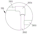
Referring to fig. 1-4, the present utility model provides a technical solution: the utility model provides an easily-cleaned agitator tank, including agitator tank main part 100 and wiper mechanism 200, agitator tank main part 100 includes the jar body 101, top cap 102, agitator motor 103 and crossbearer 104, utilize wiper mechanism 200 can carry out circumference clearance to jar body 101 inner wall, wiper mechanism 200 includes annular pipe 201, high-pressure shower nozzle 202, storage water tank 203, water pump 204, liquid pipe member 205 and apopore 206, annular pipe 201 cover is established on jar body 101, be provided with high-pressure shower nozzle 202 along its circumferencial direction between annular pipe 201 and jar body 101, circumference distribution's high-pressure shower nozzle 202 can carry out circumference clearance to jar body 101 inner wall, high-pressure shower nozzle 202 delivery port face down simultaneously, avoid the foreign matter to get into in the high-pressure shower nozzle 202, and form sixty degrees contained angles with the vertical direction, conveniently clear up jar body 101 inner wall opposite to high-pressure shower nozzle 202, water pump 204 installs in storage water tank 203 left side, water pump 204 can carry the water in the storage water tank 203 high pressure to annular pipe 201, be provided with liquid pipe member 205 between water pump 204 and the annular pipe 201, conveniently liquid gets into in the annular pipe 201.
In this embodiment, preferably, a water pumping pipe 2041 is disposed between the water pump 204 and the water storage tank 203, so that water in the water storage tank 203 can be conveniently pumped, and the inner end of the high-pressure nozzle 202 extends into the tank 101, so that water can be sprayed at high pressure on the inner wall of the tank 101, and impurities attached to the inner wall can be cleaned.
In this embodiment, preferably, the liquid tube member 205 includes connection tubes 2051, a cross tube 2052, a liquid outlet tube 2053 and a joint 2054, water can be quickly and uniformly fed into the ring tube 201 by using the liquid tube member 205, so that water can be conveniently sprayed out from the high-pressure spray head 202, two connection tubes 2051 are respectively installed on the front and rear surfaces of the ring tube 201, the cross tube 2052 is located between the two connection tubes 2051, and the joint 2054 is arranged between the cross tube 2052 and the end of the connection tube 2051, so as to realize fastening connection of the two connection tubes, the left end of the liquid outlet tube 2053 is connected with the cross tube 2052, the right end of the liquid outlet tube 2053 is connected with a water outlet on the water pump 204, so that extracted liquid can conveniently enter the liquid tube member 205.
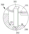
In this embodiment, preferably, the front and rear surfaces of the tank body 101 are both provided with the support assembly 300, the support assembly 300 comprises the support plate 301 and the anchor rod 302, the support assembly 300 is utilized to further play a role in supporting and stabilizing the tank body 101, the working stability of the tank body 101 is increased, one end of the support plate 301 in the Z shape is fixed on the upper end surface of the tank body 101, the other end of the support plate 301 extends to the ground, the anchor rod 302 is arranged between the lower end of the support plate 301 and the ground, fastening connection of the support plate and the ground is achieved, the inner surface of the support plate 301 is provided with the reinforcing ribs, and the installation strength of the support plate 301 is increased.
In this embodiment, preferably, a transverse frame 104 is fixed at the top of the tank 101, a top cover 102 is arranged between the transverse frame 104 and the transverse frame, a vertical cylinder is arranged at the top of the transverse frame 104, a stirring motor 103 is arranged at the top of the vertical cylinder, a stirring shaft and stirring blades are arranged at the bottom of the stirring motor 103, and the stirring shaft and the stirring blades are located in the tank 101 to rotate and stir.
The model of the water pump 204 in the present utility model IS100-65-315.
The working principle and the using flow of the utility model are as follows: the utility model discloses when using, agitator tank main part 100 stirs the work to the raw materials, and high-pressure nozzle 202 wholly is located jar body 101 upper end surface, and be located raw materials liquid level top generally, because the condition that the raw materials got into high-pressure nozzle 202 is difficult for appearing, even the condition that a small number got into high-pressure nozzle 202 appears, after the stirring was accomplished, high-pressure water flow blowout can wash out the minority raw materials that gets into, do not influence rivers and discharge, store the water that the clearance was used in storage tank 203, the water pump 204 work, take in the drinking-water pipe 2041 with the water in the storage tank 203, carry again into in the liquid pipe component 205, in the quick elasticity annular pipe 201 through liquid pipe component 205, and evenly carry into the high-pressure nozzle 202 that circumference distributes, spray at jar body 101 inner wall through high-pressure nozzle 202, clear up the attached impurity of jar body 101 inner wall, and the high-pressure nozzle 202 that circumference distributes can the at the maximum inside clearance of jar body 101 circumference, increase clearance area and avoid appearing, and the sewage after the clearance can be discharged from outlet 206, for the influence from jar body 101 jar mouth clearance, reducible, the influence on the clearance of the inner wall of the horizontal frame 104 and improvement clearance degree of the improvement of the clearance of the jar body 101.
Although embodiments of the present utility model have been shown and described in detail with reference to the foregoing detailed description, it will be understood by those skilled in the art that various changes, modifications, substitutions and alterations may be made therein without departing from the principles and spirit of the utility model, the scope of which is defined in the appended claims and their equivalents.
Claims (7)
1. The utility model provides an easily-cleaned agitator tank, includes agitator tank main part (100) and wiper mechanism (200), agitator tank main part (100) include jar body (101), top cap (102), agitator motor (103) and crossbearer (104), its characterized in that: the cleaning mechanism (200) comprises an annular pipe (201), a high-pressure spray head (202), a water storage tank (203), a water pump (204), a liquid pipe component (205) and a water outlet hole (206), wherein the annular pipe (201) is sleeved on the tank body (101), the high-pressure spray head (202) is arranged between the annular pipe (201) and the tank body (101) along the circumferential direction of the annular pipe, the water pump (204) is arranged on the left side of the water storage tank (203), the liquid pipe component (205) is arranged between the water pump (204) and the annular pipe (201), and the water outlet hole (206) is formed in the bottom surface of the tank body (101).
2. An easy-to-clean stirred tank as in claim 1, wherein: a water suction pipe (2041) is arranged between the water pump (204) and the water storage tank (203), and the inner end of the high-pressure spray head (202) extends into the tank body (101).
3. An easy-to-clean stirred tank as in claim 1, wherein: the liquid pipe component (205) comprises connecting pipes (2051), a transverse pipe (2052), a liquid outlet pipe (2053) and connectors (2054), wherein the two connecting pipes (2051) are respectively arranged on the front surface and the rear surface of the annular pipe (201), the transverse pipe (2052) is positioned between the two connecting pipes (2051), and the connectors (2054) are arranged between the transverse pipe (2052) and the end parts of the connecting pipes (2051).
4. A stirred tank for easy cleaning as in claim 3, wherein: the left end of the liquid outlet pipe (2053) is connected with the transverse pipe (2052), and the right end of the liquid outlet pipe (2053) is connected with a water outlet on the water pump (204).
5. An easy-to-clean stirred tank as in claim 1, wherein: the novel energy-saving tank is characterized in that supporting assemblies (300) are arranged on the front surface and the rear surface of the tank body (101), each supporting assembly (300) comprises a supporting plate (301) and an anchor rod (302), one end of each Z-shaped supporting plate (301) is fixed on the upper end surface of the tank body (101), and the other end of each supporting plate (301) extends to the ground.
6. An easy-to-clean stirred tank as in claim 5, wherein: an anchor rod (302) is arranged between the lower end of the supporting plate (301) and the ground, and reinforcing ribs are arranged on the inner surface of the supporting plate (301).
7. An easy-to-clean stirred tank as in claim 1, wherein: the novel stirring tank is characterized in that a transverse frame (104) is fixed at the top of the tank body (101), a top cover (102) is arranged between the transverse frame and the top, a vertical cylinder is arranged at the top of the transverse frame (104), a stirring motor (103) is arranged at the top of the vertical cylinder, and a stirring shaft and stirring blades are arranged at the bottom of the stirring motor (103).
Priority Applications (1)
| Application Number | Priority Date | Filing Date | Title |
|---|---|---|---|
| CN202223166140.5U CN219024143U (en) | 2022-11-29 | 2022-11-29 | Stirring tank easy to clean |
Applications Claiming Priority (1)
| Application Number | Priority Date | Filing Date | Title |
|---|---|---|---|
| CN202223166140.5U CN219024143U (en) | 2022-11-29 | 2022-11-29 | Stirring tank easy to clean |
Publications (1)
| Publication Number | Publication Date |
|---|---|
| CN219024143U true CN219024143U (en) | 2023-05-16 |
Family
ID=86291167
Family Applications (1)
| Application Number | Title | Priority Date | Filing Date |
|---|---|---|---|
| CN202223166140.5U Active CN219024143U (en) | 2022-11-29 | 2022-11-29 | Stirring tank easy to clean |
Country Status (1)
| Country | Link |
|---|---|
| CN (1) | CN219024143U (en) |
-
2022
- 2022-11-29 CN CN202223166140.5U patent/CN219024143U/en active Active
Similar Documents
| Publication | Publication Date | Title |
|---|---|---|
| CN210473774U (en) | High-efficient agitator tank is used in beautiful seam agent processing | |
| CN219024143U (en) | Stirring tank easy to clean | |
| CN210701555U (en) | Batching jar location belt cleaning device | |
| CN216295942U (en) | Even vacuum homogeneity batching jar of compounding | |
| CN216377860U (en) | Livestock-raising waste treatment device based on methane well | |
| CN213528333U (en) | Defoaming agitator tank is used in liquid fertile processing | |
| CN213648108U (en) | Concrete mixing device for construction engineering convenient to wash | |
| CN210492483U (en) | Egg beater convenient to clean | |
| CN208627930U (en) | A kind of cleaning device of concrete mixer truck | |
| CN206716668U (en) | A kind of electrophoresis synthesis device washer | |
| CN217121043U (en) | From high-efficient washing cauldron of taking clearance function | |
| CN219051034U (en) | Solution rapid stirring device | |
| CN216756085U (en) | Pharmacy is with diluent preparation jar | |
| CN218339501U (en) | Horizontal gypsum foaming mixer | |
| CN208617810U (en) | A kind of wheat germ ferment alcoholic drink mixed with fruit juice blend tank | |
| CN217795707U (en) | Medicinal cream stirring mixing arrangement | |
| CN210256733U (en) | Cement pit anti-setting device | |
| CN216372777U (en) | Stirring equipment with self-cleaning function for commercial building construction | |
| CN212855463U (en) | A configuration device for dislysate | |
| CN217699166U (en) | Chemical industry reation kettle convenient to clearance unloading | |
| CN214810173U (en) | Special agitator tank of high-efficient polycarboxylic acid high performance water-reducing agent production | |
| CN220176859U (en) | Reation kettle convenient to it is clean | |
| CN216654422U (en) | Material device is thrown with raw materials to liquid soap production and processing | |
| CN217434837U (en) | Latex foaming machine | |
| CN213668968U (en) | Fertile production allotment reation kettle of liquid |
Legal Events
| Date | Code | Title | Description |
|---|---|---|---|
| GR01 | Patent grant | ||
| GR01 | Patent grant |