CN219018490U - Outdoor energy storage power supply box - Google Patents
Outdoor energy storage power supply box Download PDFInfo
- Publication number
- CN219018490U CN219018490U CN202222417813.3U CN202222417813U CN219018490U CN 219018490 U CN219018490 U CN 219018490U CN 202222417813 U CN202222417813 U CN 202222417813U CN 219018490 U CN219018490 U CN 219018490U
- Authority
- CN
- China
- Prior art keywords
- power supply
- energy storage
- air inlet
- storage power
- air
- Prior art date
- Legal status (The legal status is an assumption and is not a legal conclusion. Google has not performed a legal analysis and makes no representation as to the accuracy of the status listed.)
- Active
Links
Images


Classifications
-
- Y—GENERAL TAGGING OF NEW TECHNOLOGICAL DEVELOPMENTS; GENERAL TAGGING OF CROSS-SECTIONAL TECHNOLOGIES SPANNING OVER SEVERAL SECTIONS OF THE IPC; TECHNICAL SUBJECTS COVERED BY FORMER USPC CROSS-REFERENCE ART COLLECTIONS [XRACs] AND DIGESTS
- Y02—TECHNOLOGIES OR APPLICATIONS FOR MITIGATION OR ADAPTATION AGAINST CLIMATE CHANGE
- Y02E—REDUCTION OF GREENHOUSE GAS [GHG] EMISSIONS, RELATED TO ENERGY GENERATION, TRANSMISSION OR DISTRIBUTION
- Y02E60/00—Enabling technologies; Technologies with a potential or indirect contribution to GHG emissions mitigation
- Y02E60/10—Energy storage using batteries
Landscapes
- Cooling Or The Like Of Electrical Apparatus (AREA)
Abstract
The utility model discloses an outdoor energy storage power supply box body, wherein air inlet units are arranged on two sides of the box body, baffle plates are arranged at positions, corresponding to the air inlet units, on two sides of the box body, gaps are arranged between the baffle plates and the box body, grid holes which are arranged in a staggered manner with the air inlet units are arranged on the baffle plates, an air outlet unit is arranged at one end of the box body, and an air draft device is arranged at the positions, corresponding to the air outlet units, in the box body; the heat dissipation device can effectively resist foreign matters while ensuring higher heat dissipation efficiency, and dust is not easy to accumulate after long-term use.
Description
Technical Field
The utility model belongs to the technical field of outdoor energy storage power supplies, and particularly relates to an outdoor energy storage power supply box body.
Background
With the improvement of the living standard of people, the travel demand is vigorous, and the short-distance travel fire explosion is carried out in suburbs of post epidemic situations, the outdoor high-power and high-capacity energy storage power supply gradually becomes an indispensable rigid product for people; compared with a portable charger, the outdoor energy storage device has more electric energy provided in unit time, so the heat generated by the circuit board is more concentrated, the industry solves the problem mainly by introducing a heat dissipation module consisting of a built-in air draft device and a ventilation hole, and most of the heat dissipation module consists of the following two modes: firstly, the shell is chiseled with an array through hole, so that the heat dissipation efficiency is higher, the shell has poor shielding property, external foreign matters easily enter the machine body through meshes to cause damage, and the requirements in the safety specification of an outdoor energy storage power supply can not be met; secondly, the outer layer array through holes and the inner layer metal mesh enclosure are compact in holes, foreign matters can be effectively resisted, but the heat dissipation efficiency is reduced, and dust is easy to accumulate after long-term use; the use scenario of outdoor energy storage power is restricted.
Disclosure of Invention
The utility model aims to provide an outdoor energy storage power supply box body, which can effectively resist foreign matters while ensuring higher heat dissipation efficiency, and is not easy to accumulate dust after long-term use.
In order to achieve the above purpose, the utility model is realized by the following technical scheme: the utility model provides an outdoor energy storage power supply box, which comprises a box body, the both sides of box all are equipped with the air inlet unit, the both sides in the box correspond the position department of air inlet unit all is equipped with the baffle, just the baffle with have the clearance between the box, be equipped with on the baffle with the grid hole of air inlet unit dislocation set, box one end is equipped with the air-out unit, correspond in the box the position department of air-out unit is equipped with updraft ventilator.
Further, the air inlet unit is a plurality of air inlet holes, the number of the grid holes is a plurality of, and the grid holes and the air inlet holes are staggered.
Further, the air inlet holes and the grid holes are both strip-shaped holes.
Further, the size of the air inlet hole is 25 x 2mm; the size of the grid hole is 20 x 1.5mm.
Further, the air outlet unit is a plurality of air outlet holes, and the air draft device is a fan.
Further, the upper and lower ends of the baffle are provided with brackets facing the box body.
Further, slide rails are arranged on the inner wall of the box body and located on the upper side and the lower side of the air inlet unit, and slide rails in sliding fit with the slide rails are arranged on the support.
Further, an installation seat is arranged on the slide rail, a through hole is formed in the installation seat, and an installation hole is formed in the position, corresponding to the through hole, of the slide rail.
Further, a power supply and a circuit board are arranged in the box body, and the power supply and the circuit board are arranged on the inner side of the air draft device.
Further, the box body is made of aluminum alloy.
The utility model has the following beneficial effects:
according to the outdoor energy storage power supply box body, the air suction device is utilized to suck the outside air from the air inlet hole, the air flowing in from the air inlet unit can flow through the grid holes and finally enter the box body, the air in the box body is sucked out from the air suction device and flows out from the air outlet unit, so that the air in the box body and the outside air form convection, the heat generated in the box body is brought out to the outside, the whole heat dissipation process is completed, and the outdoor energy storage power supply box body is more efficient than a single straight-through heat dissipation pipeline; and air can flow from the air inlet unit to the grid holes when flowing, because the grid holes are distributed with the air inlet unit in a staggered way and can not be directly aligned, the shielding property of the shell can be improved while higher heat dissipation efficiency is ensured, the needle-shaped objects can not pass through the outdoor energy storage power supply box body, the requirements in the safety standard of the outdoor energy storage power supply are met, other foreign matters outside can be prevented from directly entering the box body to damage components in the box body, dust is not easy to accumulate after long-term use, and the use scene is greatly widened.
Drawings
In order to more clearly illustrate the technical solutions of the embodiments of the present utility model, the drawings required for the description of the embodiments will be briefly described below, and it is obvious that the drawings in the following description are some embodiments of the present utility model, and other drawings may be obtained according to these drawings without inventive effort for a person skilled in the art.
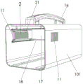
Fig. 1 is a schematic diagram of an outdoor energy storage power supply box provided by an embodiment of the utility model;
fig. 2 is a schematic diagram of an outdoor energy storage power supply box provided by an embodiment of the utility model, with a front cover removed;
FIG. 3 is a partial schematic view of a baffle and housing installation provided by an embodiment of the present utility model;
fig. 4 is a schematic diagram of distribution of air inlet holes and grid holes according to an embodiment of the present utility model.
The figure identifies the description:
1. a case; 101. a housing; 102. a front cover; 103. a rear cover; 11. an air inlet hole; 12. an air outlet hole; 13. a fan; 14. a slide rail; 15. a mounting hole; 16. a handle; 17. a power supply; 18. a circuit board; 2. a baffle; 21. grid holes; 22. a bracket; 23. a mounting base; 24. a slideway; 25. a through hole; 26. and (5) a screw.
Detailed Description
The following description of the embodiments of the present utility model will be made clearly and fully with reference to the accompanying drawings, in which it is evident that the embodiments described are some, but not all embodiments of the utility model. All other embodiments, which can be made by those skilled in the art based on the embodiments of the utility model without making any inventive effort, are intended to be within the scope of the utility model.
It should be understood that the terms "comprises" and "comprising," when used in this specification and the appended claims, specify the presence of stated features, integers, steps, operations, elements, and/or components, but do not preclude the presence or addition of one or more other features, integers, steps, operations, elements, components, and/or groups thereof.
It is also to be understood that the terminology used in the description of the utility model herein is for the purpose of describing particular embodiments only and is not intended to be limiting of the utility model. As used in this specification and the appended claims, the singular forms "a," "an," and "the" are intended to include the plural forms as well, unless the context clearly indicates otherwise.
It should be further understood that the term "and/or" as used in the present specification and the appended claims refers to any and all possible combinations of one or more of the associated listed items, and includes such combinations.
Examples
Referring to fig. 1-4, an outdoor energy storage power supply box provided by the embodiment of the utility model comprises a box body 1, wherein air inlet units are arranged on two sides of the box body 1, baffle plates 2 are arranged at positions, corresponding to the air inlet units, of the two sides in the box body 1, gaps are reserved between the baffle plates 2 and the box body 1, grid holes 21 which are arranged in a staggered manner with the air inlet units are arranged on the baffle plates 2, an air outlet unit is arranged at one end of the box body 1, and an air draft device is arranged at the position, corresponding to the air outlet unit, in the box body 1.
Through the structure, in practical application, by adopting the outdoor energy storage power supply box body of the embodiment, after the air draft device is started, external air can be sucked in from the air inlet unit, and gaps are formed between the baffle plate 2 and the box body 1, so that the baffle plate 2 and the box body 1 can not be bonded together, the air flowing in from the air inlet unit can flow through the grid holes 21 and finally enter the box body 1, the air in the box body 1 is sucked out from the air draft device and flows out from the air outlet unit, and therefore, the air in the box body 1 and the external air can form convection, heat generated in the box body 1 is brought out to the outside, the whole heat dissipation process is completed, and the heat dissipation device is more efficient than a single straight-through heat dissipation pipeline; and the air can flow from the air inlet unit to the grid holes 21 when flowing, because the grid holes 21 are distributed in a staggered manner with the air inlet unit and can not be directly aligned, the shielding performance of the box body 1 can be improved while higher heat dissipation efficiency is ensured, the needle-shaped objects can not pass through the outdoor energy storage power supply box body 1, the requirements in the safety standard of the outdoor energy storage power supply are met, other foreign matters outside can be prevented from directly entering the box body 1 to damage components in the box body 1, dust is not easily accumulated after long-term use, and the use scene is greatly widened.
Specifically, referring to fig. 1, the box 1 includes a housing 101, a front cover 102 covering the front end of the housing 101, and a rear cover 103 covering the rear end of the housing 101, where the housing 101, the front cover 102, and the rear cover 103 are made of aluminum alloy, the air inlet unit is disposed on two sides of the housing 101, the air outlet unit is disposed on the rear cover 103, and the aluminum alloy can also bring better thermal conductivity under the premise of ensuring that the housing 101, the front cover 102, and the rear cover 103 have sufficient rigidity.
Specifically, referring to fig. 1 to 4, the air inlet unit is a plurality of air inlet holes 11, the number of grid holes 21 is a plurality of, the grid holes 21 and the air inlet holes 11 are arranged in a staggered manner, the air outlet unit is a plurality of air outlet holes 12, and the air draft device is a fan 13; the staggered arrangement of the grid holes 21 with the air inlet holes 11 with the number being a plurality of can ensure that the inside of the box body 1 has enough air inlet quantity, the air outlet holes 12 with the number being a plurality of can ensure that air in the box body 1 and outside air form convection, and the existence of the fan 13 can accelerate the air convection inside and outside the box body 1, so that heat generated in the box body 1 can be quickly taken out to the outside, and the whole heat dissipation process is completed.
In this embodiment, referring to fig. 4, the air inlet holes 11 and the grid holes 21 are elongated holes, and the size of the air inlet holes is 25×2mm; the size of the grid hole is 20 x 1.5mm, so that the external foreign matters can be effectively prevented from directly entering the box body 1 while higher heat dissipation efficiency is ensured, and dust is not easy to accumulate.
Specifically, referring to fig. 3, brackets 22 are provided at the upper and lower ends of the baffle 2 toward the case 1, and the brackets 22 can support the baffle 2, so that a gap is formed between the baffle 2 and the case 1, and the baffle and the case 1 are not bonded together.
As a preferred embodiment, referring to fig. 2 to 3, in this embodiment, slide rails 14 are disposed on the inner wall of the housing 101 at the upper and lower sides of the air inlet unit, and a slide rail 24 slidably engaged with the slide rails 14 is disposed on the bracket 22; the slide way 24 is in sliding fit with the slide way 14, so that the baffle plate 2 can translate relative to the shell 101, and the relative positions of the grid holes 21 and the air inlet holes 11 can be more conveniently determined.
Further, a mounting seat 23 is arranged on the slide rail 24, a through hole 25 is arranged on the mounting seat 23, a screw 26 is penetrated in the through hole 25, and a mounting hole 15 in threaded connection with the screw 26 is arranged on the slide rail 14 at a position corresponding to the through hole 25; when the relative positions of the grid holes 21 and the air inlet holes 11 are determined through the sliding baffle plate 2, after the grid holes 21 and the air inlet holes 11 are distributed in a staggered mode, the baffle plate 2 is fixedly connected with the mounting holes 15 after passing through the through holes 25 through the screws 26, the baffle plate 2 is fixed on the inner wall of the shell 101, and the relative positions of the grid holes 21 and the air inlet holes 11 can be finely adjusted through adjusting the mounting depth of the screws 26.
In this embodiment, the handle 16 is disposed at the upper end of the housing 101, the handle 16 is convenient for carrying, the power supply 17 and the circuit board 18 are disposed in the housing 101, the fan 13 is disposed at the rear ends of the power supply 17 and the circuit board 18, in the outdoor energy storage power supply box, the power supply 17 and the circuit board 18 are the main sources of heat in the box 1, and the fan 13 is disposed at the rear ends of the power supply 17 and the circuit board 18, so as to improve heat dissipation efficiency.
While the utility model has been described with reference to certain preferred embodiments, it will be understood by those skilled in the art that various changes and substitutions of equivalents may be made and equivalents will be apparent to those skilled in the art without departing from the scope of the utility model. Therefore, the protection scope of the utility model is subject to the protection scope of the claims.
Claims (10)
1. The utility model provides an outdoor energy storage power supply box, includes the box, its characterized in that, the both sides of box all are equipped with the air inlet unit, the both sides in the box correspond the position department of air inlet unit all is equipped with the baffle, just the baffle with have the clearance between the box, be equipped with on the baffle with air inlet unit dislocation set's grating hole, box one end is equipped with the air-out unit, correspond in the box the position department of air-out unit is equipped with updraft ventilator.
2. The outdoor energy storage power supply box according to claim 1, wherein the air inlet unit is a plurality of air inlet holes, the number of the grid holes is a plurality of, and the grid holes and the air inlet holes are arranged in a staggered mode.
3. An outdoor energy storage power supply box according to claim 2, wherein the air inlet and the grille apertures are elongate apertures.
4. An outdoor energy storage power supply box according to claim 3, wherein the size of the air inlet is 25 x 2mm; the size of the grid hole is 20 x 1.5mm.
5. The outdoor energy storage power supply box of claim 4, wherein the air outlet unit is a plurality of air outlet holes, and the air extracting device is a fan.
6. An outdoor energy storage power supply box according to any of claims 1-5 and wherein the upper and lower ends of the baffle are provided with brackets disposed towards the box.
7. The outdoor energy storage power supply box according to claim 6, wherein sliding rails are arranged on the inner wall of the box and located on the upper side and the lower side of the air inlet unit, and sliding rails matched with the sliding rails in a sliding manner are arranged on the support.
8. The outdoor energy storage power supply box according to claim 7, wherein a mounting seat is arranged on the slide rail, a through hole is arranged on the mounting seat, and a mounting hole is arranged on the slide rail at a position corresponding to the through hole.
9. The outdoor energy storage power supply box according to claim 1, wherein a power supply and a circuit board are arranged in the box body, and the power supply and the circuit board are arranged on the inner side of the air draft device.
10. An outdoor energy storage power supply box according to claim 9 and wherein said box is made of aluminum alloy.
Priority Applications (1)
| Application Number | Priority Date | Filing Date | Title |
|---|---|---|---|
| CN202222417813.3U CN219018490U (en) | 2022-09-13 | 2022-09-13 | Outdoor energy storage power supply box |
Applications Claiming Priority (1)
| Application Number | Priority Date | Filing Date | Title |
|---|---|---|---|
| CN202222417813.3U CN219018490U (en) | 2022-09-13 | 2022-09-13 | Outdoor energy storage power supply box |
Publications (1)
| Publication Number | Publication Date |
|---|---|
| CN219018490U true CN219018490U (en) | 2023-05-12 |
Family
ID=86269284
Family Applications (1)
| Application Number | Title | Priority Date | Filing Date |
|---|---|---|---|
| CN202222417813.3U Active CN219018490U (en) | 2022-09-13 | 2022-09-13 | Outdoor energy storage power supply box |
Country Status (1)
| Country | Link |
|---|---|
| CN (1) | CN219018490U (en) |
-
2022
- 2022-09-13 CN CN202222417813.3U patent/CN219018490U/en active Active
Similar Documents
| Publication | Publication Date | Title |
|---|---|---|
| CN103269168B (en) | A kind of casing for installing photovoltaic combining inverter | |
| CN112242586B (en) | Battery pack mounting structure with stable electric new energy sanitation vehicle and easy heat dissipation | |
| CN219018490U (en) | Outdoor energy storage power supply box | |
| CN203826807U (en) | Box-type emergency power supply | |
| CN206713204U (en) | A kind of high-efficiency network dust-proof radiating equipment | |
| CN206517096U (en) | A kind of waterproof integrated charging device of radiating dustproof | |
| CN210379945U (en) | Heat radiator for synthesize switch board | |
| CN211046012U (en) | Electric power cabinet with high-efficient heat dissipation function | |
| CN210723820U (en) | Direct current traction substation relay protection device | |
| CN115360792A (en) | Outdoor energy storage power supply box | |
| CN212626574U (en) | Heat radiator for electronic and electrical equipment | |
| CN111800966B (en) | Power module with dustproof heat dissipation structure and use method thereof | |
| CN114760810A (en) | Energy storage power supply | |
| CN113707410A (en) | High-heat-dissipation transformer equipment for power transmission and transformation system | |
| CN216084491U (en) | High-heat-dissipation transformer equipment for power transmission and transformation system | |
| CN219717698U (en) | Environment-friendly gas insulation ring main unit | |
| CN211375537U (en) | Noiseless computer heat radiator | |
| CN213460789U (en) | High heat dissipating power equipment box | |
| CN220674208U (en) | Integrated intelligent switch module | |
| CN219304430U (en) | High-efficient heat dissipation bus duct | |
| CN221614481U (en) | Outdoor power distribution cabinet | |
| CN221264290U (en) | PCS module and energy storage cabinet | |
| CN218352992U (en) | Energy supply equipment | |
| CN221428392U (en) | Radiating structure of box-type electrical cabinet | |
| CN216960657U (en) | Energy storage power supply |
Legal Events
| Date | Code | Title | Description |
|---|---|---|---|
| GR01 | Patent grant | ||
| GR01 | Patent grant |