CN219017372U - Novel transformer convenient to installation - Google Patents
Novel transformer convenient to installation Download PDFInfo
- Publication number
- CN219017372U CN219017372U CN202222956986.2U CN202222956986U CN219017372U CN 219017372 U CN219017372 U CN 219017372U CN 202222956986 U CN202222956986 U CN 202222956986U CN 219017372 U CN219017372 U CN 219017372U
- Authority
- CN
- China
- Prior art keywords
- screw
- transformer body
- welded
- transformer
- convenient
- Prior art date
- Legal status (The legal status is an assumption and is not a legal conclusion. Google has not performed a legal analysis and makes no representation as to the accuracy of the status listed.)
- Active
Links
Images


Classifications
-
- Y—GENERAL TAGGING OF NEW TECHNOLOGICAL DEVELOPMENTS; GENERAL TAGGING OF CROSS-SECTIONAL TECHNOLOGIES SPANNING OVER SEVERAL SECTIONS OF THE IPC; TECHNICAL SUBJECTS COVERED BY FORMER USPC CROSS-REFERENCE ART COLLECTIONS [XRACs] AND DIGESTS
- Y02—TECHNOLOGIES OR APPLICATIONS FOR MITIGATION OR ADAPTATION AGAINST CLIMATE CHANGE
- Y02E—REDUCTION OF GREENHOUSE GAS [GHG] EMISSIONS, RELATED TO ENERGY GENERATION, TRANSMISSION OR DISTRIBUTION
- Y02E10/00—Energy generation through renewable energy sources
- Y02E10/50—Photovoltaic [PV] energy
Landscapes
- Housings And Mounting Of Transformers (AREA)
Abstract
The utility model relates to the technical field of transformers, in particular to a novel transformer convenient to install, which comprises the following technical scheme: caster, transformer body, first screw rod and second screw rod, transformer body bottom four corners department welds respectively has the bottom plate, and four the bottom plate bottom has welded the pillar respectively, the front and back both ends of transformer body both sides have welded the fixed plate respectively, and four the second screw has been seted up respectively to the fixed plate, and four the second screw rod is connected with the second screw meshing of four fixed plates respectively, and four the bearing is installed respectively at the truckle top, the welding has the holder respectively in transformer body top both sides, two first screw has been seted up respectively at the holder top, two first screw is connected with the first screw meshing of two holders respectively. The utility model has the advantages of facilitating the movement of the transformer body to a proper position and improving the installation efficiency.
Description
Technical Field
The utility model relates to the technical field of transformers, in particular to a novel transformer convenient to install.
Background
The transformer is a device for changing alternating voltage by utilizing the principle of electromagnetic induction, and the main components are a primary coil, a secondary coil and an iron core (magnetic core), and the main functions are as follows: voltage transformation, current transformation, impedance transformation, isolation, voltage stabilization (magnetic saturation transformers), etc., the transformers can be divided into: distribution transformers, power transformers, fully sealed transformers, combination transformers, dry transformers, oil immersed transformers, single-phase transformers, electric furnace transformers, rectifier transformers, reactors, anti-interference transformers, lightning protection transformers, box-type transformer test transformers, corner transformers, heavy current transformers, excitation transformers and the like.
Publication No.: CN209087515U, a transformer belongs to transformer component technical field, including iron core, winding subassembly, insulating pad, oil tank, oil storage cabinet, moisture absorber, extension board, clamp plate, backing plate, wherein the backing plate is fixed in transformer tank bottom, with the other end the insulating pad is fixed, the length of backing plate is less than the length of insulating pad, and the length of clamp plate is less than the length of insulating pad. The transformer provided by the utility model has the advantages that the oil in the oil tank is convenient to control, the raw materials are saved, the installation is convenient, and the normal working performance of the transformer is ensured.
In summary, oil in the transformer oil tank in the prior art CN209087515U is convenient to control, saves raw materials, is convenient to install, is favorable for guaranteeing normal working performance of the transformer, has a plurality of metal structures in the transformer shell and the inside, and causes heavy overall weight, when the transformer in the prior art CN209087515U is installed, a lifting tool is required to be used for lifting the transformer, and the transformer is in a narrow space position, and the lifting tool cannot enter and can only be lifted by a worker, so that a great amount of time is required to be consumed and the labor intensity of the worker is increased.
Disclosure of Invention
The utility model aims to provide a novel transformer convenient to install, which has the advantages of being convenient for pushing a transformer body to move to a proper position and improving the installation efficiency, and solves the problem that the traditional transformer is inconvenient to move to install when being installed in a place with a narrow space.
In order to achieve the above purpose, the present utility model provides the following technical solutions: the utility model provides a novel transformer convenient to installation, includes truckle, transformer body, first screw rod and second screw rod, transformer body bottom four corners department welds respectively has the bottom plate, four the bottom plate bottom has welded the pillar respectively, both ends welding respectively have the fixed plate around the transformer body both sides, four the second screw has been seted up respectively to the fixed plate, four the second screw rod is connected with the second screw meshing of four fixed plates respectively, four the bearing is installed respectively at truckle top, the welding has the holder respectively in transformer body top both sides, two first screw has been seted up respectively at the holder top, two first screw meshing with the first screw of two holders respectively is connected.
When the novel transformer convenient to install is used, the transformer body is lifted to the position nearby the installation position through the two lifting rings at the top of the transformer body, before the transformer body falls to the ground, the four second screw rods are rotated by using the four hand wheels, the four second screw rods are rotated and moved in the second screw holes of the four fixing plates, the four second screw rods drive the four casters to descend, the bottoms of the four casters respectively exceed the four mounting plates, the transformer body is placed on the ground, the four casters provide supporting force for the transformer body, thrust is applied to the transformer body, the transformer body is moved to the installation position through the casters, the four second screw rods are sequentially rotated reversely, the height of the transformer body is reduced, the four mounting plates are contacted with the supporting structure of the installation position, and tools such as bolts are used for fixing the transformer body through the mounting holes of the mounting plates.
Preferably, the top parts of the four second screws are respectively welded with a hand wheel, and the four hand wheels are not contacted with two sides of the transformer body. Four second screws can be rotated by using four hand wheels, and interference with the transformer body is avoided when the hand wheels are rotated.
Preferably, the bottoms of the four second screws are fixedly connected with the bearing inner rings at the tops of the four casters respectively, and the four second screws are perpendicular to the four casters. When the second screw rod rotates, the caster wheel is not driven to rotate.
Preferably, the bottom of the four fixing plates is welded with connecting blocks respectively, and one ends of the four connecting blocks, deviating from the four fixing plates, are welded with two sides of the transformer body respectively. The connecting block increases connectivity of the fixing plate and the transformer body.
Preferably, the bottom of each of the four support posts is welded with a mounting plate, and four corners of each of the four mounting plates are respectively provided with a mounting hole. The transformer body is mounted in place through the mounting holes of the mounting plate using tools such as bolts.
Preferably, the tops of the two first screws are respectively welded with a hanging ring. The transformer body is convenient to hoist by using the hoisting ring.
Preferably, a distance is reserved between the bottoms of the two first screws and the top of the transformer body. The first screw does not interfere with the transformer body.
Compared with the prior art, the utility model has the beneficial effects that:
1. according to the utility model, the transformer body is lifted to the vicinity of the installation position through the two lifting rings at the top of the transformer body by arranging the second screw rods and the truckles, before the transformer body lands, the four second screw rods are rotated by using the four hand wheels, the four second screw rods are rotated and moved in the second screw holes of the four fixing plates, the four second screw rods drive the four truckles to descend, the bottoms of the four truckles respectively exceed the four mounting plates, the transformer body is placed on the ground, the four truckles provide supporting force for the transformer body, thrust is applied to the transformer body, the transformer body is moved to the installation position through the truckles, the four second screw rods are sequentially rotated reversely, the height of the transformer body is reduced, the four mounting plates are contacted with the supporting structure of the installation position, and the transformer body is fixed by using tools such as bolts through the mounting holes of the mounting plates, so that the transformer body is conveniently pushed to move to the proper position, and the installation efficiency is improved.
Drawings
FIG. 1 is a schematic elevational view of the present utility model;
FIG. 2 is a schematic cross-sectional view of a fixing plate according to the present utility model;
FIG. 3 is a schematic cross-sectional view of a mounting plate of the present utility model;
fig. 4 is a schematic cross-sectional view of the cage of the present utility model.
In the figure: 1. casters; 2. a fixing plate; 3. a hand wheel; 4. a transformer body; 5. a retainer; 6. a hanging ring; 7. a first screw; 8. a second screw; 9. a bearing; 10. a mounting plate; 11. a support post; 12. a bottom plate; 13. a second screw hole; 14. a connecting block; 15. a mounting hole; 16. a first screw hole.
Detailed Description
The following description of the embodiments of the present utility model will be made clearly and completely with reference to the accompanying drawings, in which it is apparent that the embodiments described are only some embodiments of the present utility model, but not all embodiments. All other embodiments, which can be made by those skilled in the art based on the embodiments of the utility model without making any inventive effort, are intended to be within the scope of the utility model.
In the description of the present utility model, it should be noted that the directions or positional relationships indicated by the terms "upper", "lower", "inner", "outer", "front", "rear", "both ends", "one end", "the other end", etc. are based on the directions or positional relationships shown in the drawings, are merely for convenience of describing the present utility model and simplifying the description, and do not indicate or imply that the devices or elements referred to must have a specific direction, be configured and operated in the specific direction, and thus should not be construed as limiting the present utility model. Furthermore, the terms "first," "second," and the like, are used for descriptive purposes only and are not to be construed as indicating or implying relative importance.
In the description of the present utility model, it should be noted that, unless explicitly specified and limited otherwise, the terms "mounted," "provided," "connected," and the like are to be construed broadly, and may be fixedly connected, detachably connected, or integrally connected, for example; can be mechanically or electrically connected; can be directly connected or indirectly connected through an intermediate medium, and can be communication between two elements. The specific meaning of the above terms in the present utility model will be understood in specific cases by those of ordinary skill in the art.
The technical scheme of the utility model is further described below with reference to the attached drawings and specific embodiments.
Example 1
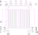
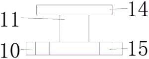
As shown in fig. 1-4, the novel transformer convenient to install comprises a caster 1, a transformer body 4, a first screw rod 7 and a second screw rod 8, wherein bottom plates 12 are respectively welded at four corners of the bottom of the transformer body 4, supporting columns 11 are respectively welded at the bottoms of the four bottom plates 12, mounting plates 10 are respectively welded at the bottoms of the four supporting columns 11, mounting holes 15 are respectively formed at the four corners of the four mounting plates 10, fixing plates 2 are respectively welded at the front end and the rear end of two sides of the transformer body 4, connecting blocks 14 are respectively welded at the bottoms of the four fixing plates 2, one ends of the four connecting blocks 14, which deviate from the four fixing plates 2, are respectively welded at two sides of the transformer body 4, second screw holes 13 are respectively formed in the four fixing plates 2, the four second screw rods 8 are respectively connected with second screw holes 13 of the four fixing plates 2 in a meshed mode, the tops of the four second screw rods 8 are respectively welded with the hand wheels 3, the four hand wheels 3 are not contacted with two sides of the transformer body 4, the tops of the four casters 1 are respectively provided with the bearings 9, the bottoms of the four second screw rods 8 are respectively fixedly connected with inner rings of the bearings 9 at the tops of the four casters 1, the four second screw rods 8 are perpendicular to the four casters 1, two sides of the top of the transformer body 4 are respectively welded with the retainers 5, the tops of the two retainers 5 are respectively provided with the first screw holes 16, the two first screw rods 7 are respectively connected with the first screw holes 16 of the two retainers 5 in a meshed mode, and the tops of the two first screw rods 7 are respectively welded with the hanging rings 6.
In this embodiment, the transformer body 4 is lifted to the vicinity of the installation position by two lifting rings 6 at the top of the transformer body 4, before the transformer body 4 falls to the ground, four second screws 8 are rotated by using four hand wheels 3, the four second screws 8 are rotated and moved in second screw holes 13 of four fixing plates 2, the four second screws 8 drive four casters 1 to descend, the bottoms of the four casters 1 respectively exceed four mounting plates 10, the transformer body 4 is placed on the ground, the four casters 1 provide supporting force for the transformer body 4, thrust is applied to the transformer body 4, the transformer body 4 is moved to the installation position by the casters 1, then the four second screws 8 are rotated reversely in turn, the height of the transformer body 4 is reduced, the four mounting plates 10 are contacted with the support structure of the installation position, and the transformer body 4 is installed and fixed by using tools such as bolts through the mounting holes 15 of the mounting plates 10.
Example two
As shown in fig. 1-4, the present utility model provides a novel transformer easy to install, and compared with the first embodiment, the present embodiment further includes: the first screw rods 7 are arranged at intervals between the bottoms of the two first screw rods 7 and the top of the transformer body 4.
In this embodiment, the distance between the bottom of the two first screws 7 and the top of the transformer body 4 does not interfere with the transformer body 4 when the first screws 7 are rotated.
It will be evident to those skilled in the art that the utility model is not limited to the details of the foregoing illustrative embodiments, and that the present utility model may be embodied in other specific forms without departing from the spirit or essential characteristics thereof. The present embodiments are, therefore, to be considered in all respects as illustrative and not restrictive, the scope of the utility model being indicated by the appended claims rather than by the foregoing description, and all changes which come within the meaning and range of equivalency of the claims are therefore intended to be embraced therein. Any reference sign in a claim should not be construed as limiting the claim concerned.
Claims (7)
1. Novel transformer convenient to installation, including truckle (1), transformer body (4), first screw rod (7) and second screw rod (8), its characterized in that: bottom plate (12) are welded respectively in four corners of the bottom of transformer body (4), four bottom plate (12) bottom has welded pillar (11) respectively, both ends have welded fixed plate (2) respectively around transformer body (4) both sides, four second screw (13) have been seted up respectively to fixed plate (2), four second screw (8) respectively with second screw (13) meshing of four fixed plate (2) be connected, four bearing (9) are installed respectively at truckle (1) top, transformer body (4) top both sides have welded holder (5) respectively, two first screw (16) have been seted up respectively at holder (5) top, two first screw (7) respectively with first screw (16) meshing of two holders (5).
2. The novel transformer convenient to install according to claim 1, wherein: the tops of the four second screws (8) are respectively welded with a hand wheel (3), and the four hand wheels (3) are not contacted with two sides of the transformer body (4).
3. The novel transformer convenient to install according to claim 1, wherein: the bottoms of the four second screws (8) are fixedly connected with the inner rings of bearings (9) at the tops of the four casters (1) respectively, and the four second screws (8) are perpendicular to the four casters (1).
4. The novel transformer convenient to install according to claim 1, wherein: the bottoms of the four fixing plates (2) are respectively welded with connecting blocks (14), and one ends of the four connecting blocks (14) deviating from the four fixing plates (2) are respectively welded with two sides of the transformer body (4).
5. The novel transformer convenient to install according to claim 1, wherein: the bottoms of the four supporting columns (11) are respectively welded with mounting plates (10), and four corners of the four mounting plates (10) are respectively provided with mounting holes (15).
6. The novel transformer convenient to install according to claim 1, wherein: hanging rings (6) are welded at the tops of the two first screw rods (7) respectively.
7. The novel transformer convenient to install according to claim 1, wherein: a distance is reserved between the bottoms of the two first screws (7) and the top of the transformer body (4).
Priority Applications (1)
| Application Number | Priority Date | Filing Date | Title |
|---|---|---|---|
| CN202222956986.2U CN219017372U (en) | 2022-11-07 | 2022-11-07 | Novel transformer convenient to installation |
Applications Claiming Priority (1)
| Application Number | Priority Date | Filing Date | Title |
|---|---|---|---|
| CN202222956986.2U CN219017372U (en) | 2022-11-07 | 2022-11-07 | Novel transformer convenient to installation |
Publications (1)
| Publication Number | Publication Date |
|---|---|
| CN219017372U true CN219017372U (en) | 2023-05-12 |
Family
ID=86243790
Family Applications (1)
| Application Number | Title | Priority Date | Filing Date |
|---|---|---|---|
| CN202222956986.2U Active CN219017372U (en) | 2022-11-07 | 2022-11-07 | Novel transformer convenient to installation |
Country Status (1)
| Country | Link |
|---|---|
| CN (1) | CN219017372U (en) |
-
2022
- 2022-11-07 CN CN202222956986.2U patent/CN219017372U/en active Active
Similar Documents
| Publication | Publication Date | Title |
|---|---|---|
| CN219017372U (en) | Novel transformer convenient to installation | |
| CN212712463U (en) | Special lifting appliance for mounting transformer | |
| CN210595146U (en) | Lifting device for be used for power equipment installation and maintain | |
| CN211667511U (en) | Lifting type transformer fixing device | |
| CN202034182U (en) | Isolation transformer for solar inversion gird connecting device | |
| CN220381887U (en) | Mounting base of power transformer | |
| CN220106178U (en) | Transformer convenient to assembly | |
| CN216945930U (en) | Transformer hoist and mount that security is good use hoist structure | |
| CN213092974U (en) | Box transformer convenient to remove | |
| CN211879179U (en) | Supporting device for three-phase dry-type transformer | |
| CN215342205U (en) | Power transformer convenient to installation | |
| CN220020824U (en) | Three-phase four-column magnetic integrated inductor | |
| CN213211858U (en) | Height-reducing transformer and vertical box transformer substation | |
| CN219163134U (en) | Combined transformer | |
| CN214002418U (en) | Support convenient to transformer transportation | |
| CN213339986U (en) | Lifting outdoor transformer | |
| CN219107264U (en) | Motor shell heating device | |
| CN210200453U (en) | Transformer easy to assemble | |
| CN214411945U (en) | Automatic compensation medium voltage switchgear | |
| CN213752221U (en) | Cascade high-voltage transformer | |
| CN214269913U (en) | Transformer hoist device for electric power construction | |
| CN212709560U (en) | Moving device for transformer | |
| CN219751630U (en) | Transformer installation hoisting frame | |
| CN215989866U (en) | Shock attenuation safe high tension switchgear | |
| CN214692849U (en) | Special equipment for hoisting transformer |
Legal Events
| Date | Code | Title | Description |
|---|---|---|---|
| GR01 | Patent grant | ||
| GR01 | Patent grant |