CN219012340U - Heat insulation strip structure of broken bridge aluminum door and window - Google Patents
Heat insulation strip structure of broken bridge aluminum door and window Download PDFInfo
- Publication number
- CN219012340U CN219012340U CN202222996298.9U CN202222996298U CN219012340U CN 219012340 U CN219012340 U CN 219012340U CN 202222996298 U CN202222996298 U CN 202222996298U CN 219012340 U CN219012340 U CN 219012340U
- Authority
- CN
- China
- Prior art keywords
- heat insulation
- strip
- auxiliary heat
- section bar
- auxiliary
- Prior art date
- Legal status (The legal status is an assumption and is not a legal conclusion. Google has not performed a legal analysis and makes no representation as to the accuracy of the status listed.)
- Active
Links
Images

Abstract
The utility model relates to the technical field of aluminum profile heat insulation, and particularly discloses a heat insulation strip structure of a bridge-cut-off aluminum door and window, which comprises a first profile, a second profile and a combined heat insulation structure; the first section bar and the second section bar are connected through a combined heat insulation structure, the combined heat insulation structure comprises a main heat insulation bar, an auxiliary heat insulation bar and an auxiliary heat insulation sleeve, and the main heat insulation bar is horizontally arranged on the first section bar and the second section bar; the connecting buckles connected with the main heat insulation strips are arranged on the first section bar and the second section bar, the auxiliary heat insulation sleeve is of a hollow structure, a heat insulation cavity is formed in the auxiliary heat insulation sleeve, and the auxiliary heat insulation strips are arranged in the heat insulation cavity. According to the scheme, the auxiliary heat insulation sleeve and the auxiliary heat insulation strip are additionally arranged on the basis of the existing heat insulation strip, so that the contact area between the auxiliary heat insulation sleeve and the sectional material can be increased through the auxiliary heat insulation sleeve, the mechanical property of the auxiliary heat insulation sleeve is enhanced through the auxiliary heat insulation strip, and the mechanical property and the sealing property of the whole heat insulation strip structure are improved.
Description
Technical Field
The utility model relates to the technical field of aluminum profile heat insulation, in particular to a heat insulation strip structure of a broken bridge aluminum door and window.
Background
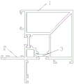
The bridge-cut-off aluminum alloy door and window section bar subassembly is mostly through dividing into inside and outside two parts with the aluminum alloy section bar, separates the heat conduction of aluminium, and the heat-proof strip is the key part that influences door and window section bar heat-proof effect. The heat insulating strip is made of polyamide, has a shape of a '1' -shaped structure, and can also play a role in blocking the heat conduction effect of the inner aluminum alloy frame and the outer aluminum alloy frame, but has smaller cross-sectional area with the section bar, relatively weaker mechanical property and lower safety coefficient. Moreover, when the heat insulation strip is installed, corresponding grooves are mostly formed in the joint of the heat insulation strip and the aluminum profile, and then two ends of the heat insulation strip are embedded into the corresponding grooves, so that the sealing structure is single, and the sealing performance of the heat insulation strip is weak.
Disclosure of Invention
The utility model aims to provide a broken bridge aluminum door and window heat insulation strip structure so as to solve the problems in the background technology.
In order to achieve the above purpose, the present utility model provides the following technical solutions: a heat insulation strip structure of a bridge-cut-off aluminum door and window comprises a first section bar, a second section bar and a combined heat insulation structure; the first section bar and the second section bar are connected through a combined heat insulation structure, the combined heat insulation structure comprises a main heat insulation bar, an auxiliary heat insulation bar and an auxiliary heat insulation sleeve, and the main heat insulation bar is horizontally arranged on the first section bar and the second section bar;
the first section bar and the second section bar are respectively provided with a connecting buckle connected with the main heat insulation strip, the auxiliary heat insulation sleeve is of a hollow structure, a heat insulation cavity is formed in the auxiliary heat insulation sleeve, and an auxiliary heat insulation strip is arranged in the heat insulation cavity; connecting buckles are also arranged on the inner walls of the left side and the right side of the heat insulation cavity, and the left end and the right end of the auxiliary heat insulation strip are embedded into the positioning clamping grooves;
the left and right side walls of the auxiliary heat insulation sleeve are tightly attached to the side walls of the connecting buckle, an elastic sealing strip is arranged at one end, far away from the main heat insulation strip, of the auxiliary heat insulation sleeve, and the elastic sealing strip is tightly attached to the side walls of the connecting buckle.
Preferably, the main heat insulation strip comprises a horizontal strip and positioning chucks, the positioning chucks are respectively arranged at the left side and the right side of the horizontal strip, positioning clamping grooves are formed in the connecting buckles, and the positioning chucks are embedded into the positioning clamping grooves.
Preferably, the auxiliary heat insulation strip is consistent with the main heat insulation strip in structure and different in size, and the positioning clamping head of the auxiliary heat insulation strip is embedded in the positioning clamping groove.
Preferably, the inside and outside both sides of main heat insulating strip all are provided with vice insulating sheath, and vice insulating sheath's cross-section is "U" shape structure.
Preferably, the elastic sealing strip is obliquely arranged on the auxiliary heat insulation sleeve, and the included angle between the elastic sealing strip and the positioning clamping head is smaller than the included angle between the auxiliary heat insulation strip and the positioning clamping head.
Preferably, the left side wall and the right side wall of the auxiliary heat insulation sleeve are respectively provided with a serrated sealing rack, the connecting buckle is provided with a sealing tooth slot matched with the sealing racks, and the sealing racks are clamped in the sealing tooth slots.
Compared with the prior art, the utility model has the beneficial effects that:
according to the technical problem that the mechanical property and the sealing property of the existing heat insulation strip structure are weak, the heat insulation strip structure is designed into a combined structure, and the auxiliary heat insulation sleeve and the auxiliary heat insulation strip are additionally arranged on the basis of the existing heat insulation strip, so that the contact area between the heat insulation strip and a section bar can be increased through the auxiliary heat insulation sleeve, the mechanical property of the auxiliary heat insulation sleeve is enhanced through the auxiliary heat insulation strip, and the mechanical property and the sealing property of the whole heat insulation strip structure are further improved.
Drawings
FIG. 1 is a schematic view of a mounting structure of a conventional heat insulating strip;
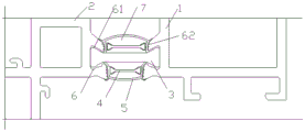
FIG. 2 is a schematic view of the mounting structure of the present utility model;
fig. 3 is a schematic structural diagram of the present utility model.
In the figure: 1. a first profile; 2. a second profile; 3. a primary insulating strip; 31. a horizontal bar; 32. positioning a clamping head; 4. a secondary insulating strip; 5. an auxiliary heat insulation sleeve; 51. an elastic sealing strip; 52. a sealing rack; 6. a connecting buckle; 61. positioning clamping grooves; 62. sealing the tooth slot; 7. and a heat insulation cavity.
Detailed Description
The following description of the embodiments of the present utility model will be made clearly and completely with reference to the accompanying drawings, in which it is apparent that the embodiments described are only some embodiments of the present utility model, but not all embodiments. All other embodiments, which can be made by those skilled in the art based on the embodiments of the utility model without making any inventive effort, are intended to be within the scope of the utility model.
In the description of the present utility model, it should be noted that the azimuth or positional relationship indicated by the terms "vertical", "upper", "lower", "horizontal", etc. are based on the azimuth or positional relationship shown in the drawings, and are merely for convenience of describing the present utility model and simplifying the description, and do not indicate or imply that the apparatus or element referred to must have a specific azimuth, be constructed and operated in a specific azimuth, and thus should not be construed as limiting the present utility model.
In the description of the present utility model, it should also be noted that, unless explicitly specified and limited otherwise, the terms "disposed," "mounted," "connected," and "connected" are to be construed broadly, and may be, for example, fixedly connected, detachably connected, or integrally connected; can be mechanically or electrically connected; can be directly connected or indirectly connected through an intermediate medium, and can be communication between two elements. The specific meaning of the above terms in the present utility model can be understood by those of ordinary skill in the art according to the specific circumstances.
Any one embodiment of the present utility model is described below with reference to fig. 1 to 3 for further explanation:
example 1: a heat insulation strip structure of a bridge-cut-off aluminum door and window comprises a first section bar 1, a second section bar 2 and a combined heat insulation structure; the first section bar 1 and the second section bar 2 are connected through a combined heat insulation structure, the combined heat insulation structure comprises a main heat insulation strip 3 and a secondary heat insulation sleeve 5, and the main heat insulation strip 3 is horizontally arranged on the first section bar 1 and the second section bar 2;
the first section bar 1 and the second section bar 2 are respectively provided with a connecting buckle 6 connected with the main heat insulation strip 3, the connecting buckles 6 are arranged at the left side and the right side of the horizontal strip 31, and the connecting buckles 6 are provided with positioning clamping grooves 61; the main heat insulation strip 3 comprises a horizontal strip 31 and a positioning clamping head 32, and the positioning clamping head 32 is embedded into the positioning clamping groove 61;
the auxiliary heat insulation sleeve 5 is of a hollow structure, a heat insulation cavity 7 is arranged in the auxiliary heat insulation sleeve 5, and the side walls of the left side and the right side of the auxiliary heat insulation sleeve 5 are tightly attached to the side walls of the connecting buckle 6.
Preferably, the inner side and the outer side of the main heat insulation strip 3 are both provided with auxiliary heat insulation sleeves 5, and the section of each auxiliary heat insulation sleeve 5 is of a U-shaped structure.
In this embodiment: the first section bar 1 in this scheme, link to each other through main insulating strip 3 between the second section bar 2, and the inside and outside both sides of main insulating strip 3 all are provided with vice insulating sleeve 5, make it can play thermal-insulated, sealed effect through main insulating strip 3, vice insulating sleeve 5, increase through vice insulating sleeve 5 with the contact area of section bar, strengthen the holistic mechanical properties of insulating strip structure, the heat conduction effect inside and outside the separation section bar, mechanical properties is higher, have ultra-high factor of safety.
Example 2: the combined heat insulation structure further comprises a secondary heat insulation strip 4, and the secondary heat insulation strip 4 is arranged in the heat insulation cavity 7; the inner walls of the left side and the right side of the heat insulation cavity 7 are also provided with connecting buckles 6, and the left end and the right end of the auxiliary heat insulation strip 4 are embedded and arranged in the positioning clamping grooves 61.
Preferably, the secondary heat insulation strip 4 has the same structure as the primary heat insulation strip 3, and has different sizes, and the positioning clamping head 32 of the secondary heat insulation strip 4 is embedded in the positioning clamping groove 61.
In this embodiment: the scheme is provided with the auxiliary heat insulation strip 4 in the heat insulation cavity 7, so that the auxiliary heat insulation strip 4 can strengthen the mechanical property of the auxiliary heat insulation sleeve 5, and further the mechanical property and the sealing property of the whole heat insulation strip structure are guaranteed.
Example 3: one end of the auxiliary heat insulation sleeve 5 far away from the main heat insulation strip 3 is provided with an elastic sealing strip 51, and the elastic sealing strip 51 is tightly attached to the side wall of the connecting buckle 6.
Preferably, the elastic sealing strip 51 is obliquely arranged on the auxiliary heat insulation sleeve 5, and the included angle between the elastic sealing strip 51 and the positioning clamping head 32 is smaller than the included angle between the auxiliary heat insulation strip 4 and the positioning clamping head 32.
In this embodiment: according to the scheme, the elastic sealing strip 51 is additionally arranged on the auxiliary heat insulation sleeve 5, so that in the practical application process of the auxiliary heat insulation sleeve 5, the outer end of the auxiliary heat insulation sleeve can be tightly abutted to the side wall of the corresponding section bar through the elasticity and the resetting performance of the elastic sealing strip 51, and the connection tightness and the tightness between the auxiliary heat insulation sleeve 5 and the section bar are enhanced.
Example 4: the left and right side walls of the auxiliary heat insulation sleeve 5 are respectively provided with a serrated sealing rack 52, the connecting buckle 6 is provided with a sealing tooth slot 62 matched with the sealing racks 52, and the sealing racks 52 are clamped in the sealing tooth slots 62.
In this embodiment: according to the scheme, the sealing rack 52 matched with the connecting buckle 6 is additionally arranged on the auxiliary heat insulation sleeve 5, so that the multistage sealing function of the auxiliary heat insulation sleeve 5 can be increased, and the connection tightness and tightness between the auxiliary heat insulation sleeve 5 and the sectional material are improved.
Although embodiments of the present utility model have been shown and described, it will be understood by those skilled in the art that various changes, modifications, substitutions and alterations can be made therein without departing from the principles and spirit of the utility model, the scope of which is defined in the appended claims and their equivalents.
Claims (6)
1. A bridge cut-off aluminium door and window heat insulating strip structure, its characterized in that: comprises a first section bar (1), a second section bar (2) and a combined heat insulation structure; the first section bar (1) and the second section bar (2) are connected through a combined heat insulation structure, the combined heat insulation structure comprises a main heat insulation bar (3), an auxiliary heat insulation bar (4) and an auxiliary heat insulation sleeve (5), and the main heat insulation bar (3) is horizontally arranged on the first section bar (1) and the second section bar (2);
the connecting buckles (6) connected with the main heat insulation strips (3) are arranged on the first section bar (1) and the second section bar (2), the auxiliary heat insulation sleeve (5) is of a hollow structure, a heat insulation cavity (7) is arranged in the auxiliary heat insulation sleeve (5), and an auxiliary heat insulation strip (4) is arranged in the heat insulation cavity (7); connecting buckles (6) are also arranged on the inner walls of the left side and the right side of the heat insulation cavity (7), and the left end and the right end of the auxiliary heat insulation strip (4) are embedded in the connecting buckles (6);
the side walls of the left side and the right side of the auxiliary heat insulation sleeve (5) are tightly attached to the side wall of the connecting buckle (6), an elastic sealing strip (51) is arranged at one end, far away from the main heat insulation strip (3), of the auxiliary heat insulation sleeve (5), and the elastic sealing strip (51) is tightly attached to the side wall of the connecting buckle (6).
2. The bridge-cut-off aluminum door and window heat insulating strip structure according to claim 1, wherein: the main heat insulation strip (3) comprises a horizontal strip (31) and positioning clamping heads (32), wherein the positioning clamping heads (32) are respectively arranged on the left side and the right side of the horizontal strip (31), positioning clamping grooves (61) are formed in the connecting buckles (6), and the positioning clamping heads (32) are embedded into the positioning clamping grooves (61).
3. The bridge-cut-off aluminum door and window heat insulating strip structure according to claim 1, wherein: the auxiliary heat insulation strip (4) is consistent with the main heat insulation strip (3) in structure and different in size, and the positioning clamping head (32) of the auxiliary heat insulation strip (4) is embedded into the positioning clamping groove (61).
4. The bridge-cut-off aluminum door and window heat insulating strip structure according to claim 1, wherein: the inner side and the outer side of the main heat insulation strip (3) are respectively provided with an auxiliary heat insulation sleeve (5), and the section of the auxiliary heat insulation sleeve (5) is of a U-shaped structure.
5. The bridge-cut-off aluminum door and window heat insulating strip structure according to claim 1, wherein: the elastic sealing strip (51) is obliquely arranged on the auxiliary heat insulation sleeve (5), and the included angle between the elastic sealing strip (51) and the positioning clamping head (32) is smaller than the included angle between the auxiliary heat insulation strip (4) and the positioning clamping head (32).
6. The bridge-cut-off aluminum door and window heat insulating strip structure according to claim 1, wherein: the left side wall and the right side wall of the auxiliary heat insulation sleeve (5) are respectively provided with a serrated sealing rack (52), the connecting buckle (6) is provided with a sealing tooth slot (62) matched with the sealing racks (52), and the sealing racks (52) are clamped in the sealing tooth slots (62).
Priority Applications (1)
| Application Number | Priority Date | Filing Date | Title |
|---|---|---|---|
| CN202222996298.9U CN219012340U (en) | 2022-11-10 | 2022-11-10 | Heat insulation strip structure of broken bridge aluminum door and window |
Applications Claiming Priority (1)
| Application Number | Priority Date | Filing Date | Title |
|---|---|---|---|
| CN202222996298.9U CN219012340U (en) | 2022-11-10 | 2022-11-10 | Heat insulation strip structure of broken bridge aluminum door and window |
Publications (1)
| Publication Number | Publication Date |
|---|---|
| CN219012340U true CN219012340U (en) | 2023-05-12 |
Family
ID=86245070
Family Applications (1)
| Application Number | Title | Priority Date | Filing Date |
|---|---|---|---|
| CN202222996298.9U Active CN219012340U (en) | 2022-11-10 | 2022-11-10 | Heat insulation strip structure of broken bridge aluminum door and window |
Country Status (1)
| Country | Link |
|---|---|
| CN (1) | CN219012340U (en) |
-
2022
- 2022-11-10 CN CN202222996298.9U patent/CN219012340U/en active Active
Similar Documents
| Publication | Publication Date | Title |
|---|---|---|
| CN219012340U (en) | Heat insulation strip structure of broken bridge aluminum door and window | |
| CN211524525U (en) | Double-broken-bridge heat insulation type door and window structure | |
| CN218265582U (en) | Novel energy-saving aluminum-plastic window structure | |
| CN219012337U (en) | Outward-opening node type window structure | |
| CN219138811U (en) | Low-energy consumption aluminum-plastic profile for energy-saving doors and windows | |
| CN220748007U (en) | High-strength heat insulation strip and profile frame thereof | |
| CN215804241U (en) | Clearance seal structure and aluminum alloy door and window | |
| CN219012336U (en) | Inward-opening node type window structure | |
| CN220184955U (en) | Square wire pressing structure and window frame | |
| CN211173767U (en) | Building door and window arbitrary angle switching structure | |
| CN217206035U (en) | 90-degree corner heat insulation strip structure and composite corner profile | |
| CN214659696U (en) | Bridge cut-off heat-insulating aluminum alloy door and window structure | |
| CN217269686U (en) | Partition section bar for sliding window | |
| CN217735253U (en) | Glue injection heat insulation aluminum alloy section | |
| CN217735250U (en) | Heat insulation window | |
| CN210622601U (en) | Atrium connector | |
| CN211115459U (en) | Frame assembly of outward-opening door with external heat preservation function | |
| CN211342502U (en) | Door and window glass mounting and fixing structure | |
| CN218265580U (en) | Novel heat insulation strip | |
| CN215565348U (en) | Heat insulation section bar connecting structure | |
| CN214740915U (en) | Heat insulation type aluminum alloy door and window frame structure | |
| CN215671776U (en) | Window sash with length-adjustable heat insulation strips | |
| CN214835945U (en) | Door and window adhesive tape corner sealing device | |
| CN213063353U (en) | Super energy-saving heat-insulating glass window with built-in polyurethane foam strip | |
| CN211342448U (en) | Waterproof flat window structure |
Legal Events
| Date | Code | Title | Description |
|---|---|---|---|
| GR01 | Patent grant | ||
| GR01 | Patent grant |