CN219010557U - Carbon fiber upper pin - Google Patents
Carbon fiber upper pin Download PDFInfo
- Publication number
- CN219010557U CN219010557U CN202320020110.9U CN202320020110U CN219010557U CN 219010557 U CN219010557 U CN 219010557U CN 202320020110 U CN202320020110 U CN 202320020110U CN 219010557 U CN219010557 U CN 219010557U
- Authority
- CN
- China
- Prior art keywords
- block
- fixedly connected
- pin body
- connecting piece
- wall
- Prior art date
- Legal status (The legal status is an assumption and is not a legal conclusion. Google has not performed a legal analysis and makes no representation as to the accuracy of the status listed.)
- Active
Links
Images


Landscapes
- Mutual Connection Of Rods And Tubes (AREA)
Abstract
The utility model belongs to the technical field of spinning frames, in particular to a carbon fiber upper pin, which comprises a pin body and a reinforcing device, wherein a connecting piece is fixedly connected to the surface of the pin body; the surface of the connecting piece is provided with a reinforcing device, the reinforcing device comprises a connecting block, the connecting block is positioned on the side wall of the connecting piece, the side wall of the connecting block is fixedly connected with a supporting block, both sides of the supporting block are rotationally connected with a main rod, the inner wall of the supporting block is slidably connected with an auxiliary rod, the surface of the pin body is provided with two anti-skid devices, each anti-skid device comprises an anti-skid sleeve, the anti-skid sleeve is sleeved on the surface of the pin body, the surface of the anti-skid sleeve is fixedly connected with four clamping blocks, and the position of the surface of the pin body, which is close to the clamping blocks, is fixedly connected with a stop block; can increase the control to fibrous through setting up main stick and vice stick, also can let the fibre remove along specific direction simultaneously to reach the quality that improves into yarn, and the setting of threaded rod can be convenient to the adjustment of main stick and vice stick, increases the adaptation ability to the in-service use demand.
Description
Technical Field
The utility model relates to the technical field of spinning frames, in particular to a carbon fiber upper pin.
Background
In the spinning process, the semi-product roving or sliver is drawn, combined and wound into a spinning machine of spun yarn cop, the sliver is drawn and combined on the roving machine to form the roving, the fiber is combed into combed sliver by the combing machine, the sliver is combined by the gilling machine, the sliver structure is improved by the needle draft, and the roving is further combined on the ring spinning machine to form the spun yarn, and the spinning machine is a main machine for spinning. The output and quality of spun yarn are the comprehensive reflection of the quality of each process in spinning technology.
One Chinese patent of the Chinese patent application CN212335397U discloses an upper pin for a spinning frame, and the technical scheme is as follows: the position of the panel main body can be limited by arranging the first limiting block and the second limiting block, the panel main body is prevented from being too high in position, the bayonet is arranged through the bayonet, the periphery of the bayonet is slightly higher than the bottom wall of the panel clamping groove, and therefore the panel main body can be prevented from being too low in position, normal operation and stability of the device are guaranteed on one hand, and plastic deformation is prevented from being caused by overlarge tensile or compressive strength of the spring on the other hand, and damage to the spring is avoided.
With respect to the above and related art, the inventors believe that there are often the following drawbacks: when the spinning frame is used, the upper pin is required to be arranged in the traction area, and most of the upper pins are integrally formed during use, so that accessories capable of increasing the practicability of the upper pins are fewer during use, and the problem of poor practicability of the traditional pins is likely to occur during actual use; therefore, a carbon fiber upper pin is proposed for the above-mentioned problems.
Disclosure of Invention
In order to make up the deficiency of the prior art, the utility model solves the problems that the upper pin is required to be arranged in a traction area when a spinning frame is used, and the upper pin is required to be integrally formed in most parts when the spinning frame is used, so that accessories capable of increasing the practicability of the upper pin are fewer in the use process, and the practicability of the upper pin is poor in the traditional use process.
The technical scheme adopted for solving the technical problems is as follows: the utility model relates to a carbon fiber upper pin, which comprises a pin body and a reinforcing device, wherein a connecting piece is fixedly connected to the surface of the pin body; the surface of connecting piece is equipped with reinforcing means, reinforcing means includes the connecting block, the connecting block is located the lateral wall of connecting piece, the lateral wall fixedly connected with supporting shoe of connecting block, the both sides of supporting shoe are all rotated and are connected with main stick, the inner wall sliding connection of supporting shoe has vice stick, passes the position between vice stick and the main stick with the fibre, and vice stick and main stick can increase into yarn quality to tensile fibre to a certain extent.
Preferably, the inner wall threaded connection of connecting block and connecting piece has a plurality of locating pins, the spout has been seted up on the surface of supporting shoe, the spout inner wall sliding connection of vice excellent surface and supporting shoe rotates the locating pin to connecting block and connecting piece inner wall, and the locating pin can restrict the position between connecting block and the connecting piece.
Preferably, the inner wall rotation of supporting shoe is connected with two threaded rods, the lateral wall fixedly connected with knob of threaded rod, when needs rotate the threaded rod, promotes the knob and lets the knob drive the threaded rod and rotate, and the threaded rod rotates at the supporting shoe inner wall, and the knob can make things convenient for the threaded rod to rotate to a certain extent.
Preferably, the position that auxiliary rod surface is close to the threaded rod has offered the screw hole, the screw hole inner wall and the threaded rod surface threaded connection of auxiliary rod, the equal fixedly connected with of upper and lower both ends of auxiliary rod are a plurality of stoppers, the stopper is located the surface of supporting shoe, can rotate at the screw hole inner wall of auxiliary rod when the threaded rod rotates, and auxiliary rod can be because the rotation displacement position of threaded rod, and the setting of threaded rod can be to a certain extent convenient adjustment auxiliary rod's position.
Preferably, the surface of the pin body is provided with two anti-skidding devices, each anti-skidding device comprises an anti-skidding sleeve, each anti-skidding sleeve is sleeved on the surface of the pin body, each anti-skidding sleeve is fixedly connected with four clamping blocks, each clamping block is fixedly connected with a stop block at a position, which is close to each clamping block, of the surface of each pin body, each clamping block is sleeved on the surface of each stop block, each clamping block is aligned to each stop block when the pin body is required to be used, each anti-skidding sleeve is pushed to drive each clamping block to slide, each clamping block is sleeved on the surface of each stop block, and each anti-skidding sleeve can reduce the possibility of skidding when the pin body is connected with other objects to a certain extent.
Preferably, the draw-in groove has been seted up on the surface of fixture block, the draw-in groove inner wall at the fixture block is inserted to the dog, the equal fixedly connected with of both sides of dog is a plurality of antislip strips, the antislip strip is located the draw-in groove inner wall of dog, and when the fixture block slides, the fixture block can accomodate inner wall with dog and antislip strip through the draw-in groove, and dog, fixture block and antislip strip can restrict the antiskid cover in the position on the pin body surface.
The utility model has the advantages that: 1. according to the utility model, when the practical capability of a pin body is required to be increased, the connecting block is attached to the connecting piece, the positioning pin is rotated to the inner walls of the connecting block and the connecting piece, the knob is rotated to drive the knob to rotate, the threaded rod rotates on the inner wall of the supporting block, the threaded rod simultaneously rotates on the inner wall of the threaded hole of the auxiliary rod, the auxiliary rod slides on the inner wall of the supporting block, the auxiliary rod slides on the limiting block when sliding, the limiting block slides on the surface of the supporting block, after the auxiliary rod slides to a proper position, the knob is stopped to rotate, the limiting block is wound on the surfaces of the main rod and the auxiliary rod, the control of fibers can be increased through arranging the main rod and the auxiliary rod, and meanwhile, the fibers can be moved along a specific direction, so that the quality of finished yarn is improved, the threaded rod is convenient to adjust the main rod and the auxiliary rod, and the adaptive capability to the actual use requirement is increased.
2. When the pin body is required to be mounted on other equipment, the clamping block on the anti-slip sleeve is aligned with the stop block, then the anti-slip sleeve is pushed to drive the clamping block to slide, the clamping block is sleeved on the surface of the stop block through the clamping groove, the anti-slip strip on the stop block can be extruded on the inner wall of the clamping groove of the clamping block, after the anti-slip sleeve is arranged, the pin body is mounted on other objects, the anti-slip sleeve can be attached to the other objects during mounting, the possibility of the pin body moving on other equipment can be reduced through the arrangement of the anti-slip sleeve, and meanwhile gaps between the pin body and the other equipment can be filled by the anti-slip sleeve.
Drawings
In order to more clearly illustrate the embodiments of the utility model or the technical solutions of the prior art, the drawings which are used in the description of the embodiments or the prior art will be briefly described, it being obvious that the drawings in the description below are only some embodiments of the utility model, and that other drawings can be obtained from these drawings without inventive faculty for a person skilled in the art.
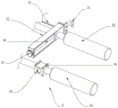
Fig. 1 is a schematic perspective view of a pin body according to a first embodiment.
Fig. 2 is a schematic view of a part of the structure of the reinforcing apparatus in the first embodiment.
Fig. 3 is a schematic diagram of a structure at a in fig. 1 in a first embodiment.
Fig. 4 is a schematic view of a part of the structure of an anti-skid device in the first embodiment.
In the figure: 1. a pin body; 2. a connecting piece; 3. a reinforcing means; 31. a connecting block; 32. a support block; 33. a main bar; 34. an auxiliary rod; 35. a positioning pin; 36. a threaded rod; 37. a knob; 38. a threaded hole; 39. a limiting block; 4. an anti-slip device; 41. an anti-skid sleeve; 42. a clamping block; 43. a stop block; 44. a clamping groove; 45. an anti-slip strip.
Detailed Description
The following description of the embodiments of the present utility model will be made clearly and completely with reference to the accompanying drawings, in which it is apparent that the embodiments described are only some embodiments of the present utility model, but not all embodiments. All other embodiments, which can be made by those skilled in the art based on the embodiments of the utility model without making any inventive effort, are intended to be within the scope of the utility model.
Example 1
Referring to fig. 1-4, a carbon fiber upper pin comprises a pin body 1 and a reinforcing device 3, wherein a connecting piece 2 is fixedly connected to the surface of the pin body 1; the surface of the connecting piece 2 is provided with a reinforcing device 3, the reinforcing device 3 comprises a connecting block 31, the connecting block 31 is positioned on the side wall of the connecting piece 2, the side wall of the connecting block 31 is fixedly connected with a supporting block 32, two sides of the supporting block 32 are rotatably connected with a main rod 33, and the inner wall of the supporting block 32 is slidably connected with an auxiliary rod 34; when the connecting piece 2 is needed to be used in operation, the connecting piece 31 is attached to the connecting piece 2, then the auxiliary rod 34 is pushed to enable the auxiliary rod 34 to slide on the inner wall of the supporting block 32, after the auxiliary rod 34 slides to a proper position, fibers pass through the position between the auxiliary rod 34 and the main rod 33, and the auxiliary rod 34 and the main rod 33 can stretch the fibers to a certain extent to increase the quality of the spun yarn.
The connecting block 31 and the inner wall of the connecting piece 2 are in threaded connection with a plurality of positioning pins 35, the surface of the supporting block 32 is provided with a sliding groove, and the outer surface of the auxiliary rod 34 is in sliding connection with the inner wall of the sliding groove of the supporting block 32; during operation, after connecting block 31 and connecting piece 2 laminating, rotate connecting block 31 and connecting piece 2 inner wall with locating pin 35, locating pin 35 can restrict the position between connecting block 31 and the connecting piece 2.
The inner wall of the supporting block 32 is rotatably connected with two threaded rods 36, and the side wall of each threaded rod 36 is fixedly connected with a knob 37; when the screw rod 36 is required to be rotated during operation, the knob 37 is pushed to enable the knob 37 to drive the screw rod 36 to rotate, the screw rod 36 rotates on the inner wall of the supporting block 32, and the knob 37 can facilitate the rotation of the screw rod 36 to a certain extent.
A threaded hole 38 is formed in the surface of the auxiliary rod 34 near the threaded rod 36, the inner wall of the threaded hole 38 of the auxiliary rod 34 is in threaded connection with the outer surface of the threaded rod 36, a plurality of limiting blocks 39 are fixedly connected to the upper end and the lower end of the auxiliary rod 34, and the limiting blocks 39 are positioned on the surface of the supporting block 32; during operation, when the threaded rod 36 rotates, the inner wall of the threaded hole 38 of the auxiliary rod 34 rotates, the auxiliary rod 34 moves in position due to the rotation of the threaded rod 36, the auxiliary rod 34 slides while sliding to drive the limiting block 39 to slide on the surface of the supporting block 32, and the position of the auxiliary rod 34 can be conveniently adjusted to a certain extent due to the arrangement of the threaded rod 36.
The surface of the pin body 1 is provided with two anti-skid devices 4, each anti-skid device 4 comprises an anti-skid sleeve 41, each anti-skid sleeve 41 is sleeved on the surface of the pin body 1, four clamping blocks 42 are fixedly connected to the surface of each anti-skid sleeve 41, a stop block 43 is fixedly connected to the surface of the pin body 1 close to each clamping block 42, and each clamping block 42 is sleeved on the surface of each stop block 43; when the pin body 1 is needed to be used in operation, the clamping block 42 is aligned with the stop block 43, then the anti-slip sleeve 41 is pushed to enable the anti-slip sleeve 41 to drive the clamping block 42 to slide, the clamping block 42 is sleeved on the surface of the stop block 43, and the possibility of slipping when the pin body 1 is connected with other objects can be reduced to a certain extent by the anti-slip sleeve 41.
The surface of the clamping block 42 is provided with a clamping groove 44, the stop block 43 is inserted into the inner wall of the clamping groove 44 of the clamping block 42, a plurality of anti-slip strips 45 are fixedly connected to two sides of the stop block 43, and the anti-slip strips 45 are positioned on the inner wall of the clamping groove 44 of the stop block 43; when the locking block 42 slides during operation, the locking block 42 can store the stop block 43 and the anti-slip strip 45 into the inner wall through the locking groove 44, and the stop block 43, the locking block 42 and the anti-slip strip 45 can limit the position of the anti-slip sleeve 41 on the surface of the pin body 1.
The theory of operation, when the practical ability of the pin body 1 needs to be increased, laminating connecting piece 2 with connecting piece 31, then rotate connecting piece 31 and connecting piece 2 inner wall with locating pin 35, rotate knob 37 again and let knob 37 drive threaded rod 36 rotate, threaded rod 36 rotates at supporting shoe 32 inner wall, threaded rod 36 also can rotate at the screw hole 38 inner wall of auxiliary rod 34, auxiliary rod 34 can slide at supporting shoe 32 inner wall, auxiliary rod 34 can drive stopper 39 and slide when auxiliary rod 34 slides, stopper 39 slides on supporting shoe 32 surface, after auxiliary rod 34 slides suitable position, then with spacing winding at main rod 33 and auxiliary rod 34 surface, can increase the control to the fibre through setting up main rod 33 and auxiliary rod 34, simultaneously also can let the fibre remove along specific direction, thereby reach the quality that improves the yarn, and the setting of 36 can conveniently be to the adjustment of main rod 33 and auxiliary rod 34, increase the adaptation ability to the in-service requirement, when needs install pin body 1 on other equipment, can drive stopper 41 on the stopper 42, then the anti-slip block 42 can be aimed at the stopper 41 on the anti-slip groove 42, can be installed on other equipment 45 and can be reduced at other anti-slip groove 41, can be filled up at other anti-slip groove 41, can be installed on the anti-slip body 41 through the anti-slip groove 41, and other anti-slip device 41, can be installed on the anti-slip groove 41, and other anti-slip device 41 can be equipped with other anti-slip device 41, and the anti-skid device 45 can be passed through the anti-skid sleeve 41 and the anti-skid device 41.
In the description of the present specification, the descriptions of the terms "one embodiment," "example," "specific example," and the like, mean that a particular feature, structure, material, or characteristic described in connection with the embodiment or example is included in at least one embodiment or example of the present utility model. In this specification, schematic representations of the above terms do not necessarily refer to the same embodiments or examples. Furthermore, the particular features, structures, materials, or characteristics described may be combined in any suitable manner in any one or more embodiments or examples.
The foregoing has shown and described the basic principles, principal features and advantages of the utility model. It will be understood by those skilled in the art that the present utility model is not limited to the embodiments described above, and that the above embodiments and descriptions are merely illustrative of the principles of the present utility model, and various changes and modifications may be made without departing from the spirit and scope of the utility model, which is defined in the appended claims.
Claims (6)
1. The carbon fiber upper pin comprises a pin body (1) and a reinforcing device (3), wherein a connecting piece (2) is fixedly connected to the surface of the pin body (1); the method is characterized in that: the surface of connecting piece (2) is equipped with reinforcing means (3), reinforcing means (3) are including connecting block (31), connecting block (31) are located the lateral wall of connecting piece (2), lateral wall fixedly connected with supporting shoe (32) of connecting block (31), the both sides of supporting shoe (32) all rotate and are connected with main stick (33), the inner wall sliding connection of supporting shoe (32) has auxiliary stick (34).
2. A carbon fiber upper pin according to claim 1, wherein: the inner wall threaded connection of connecting block (31) and connecting piece (2) has a plurality of locating pins (35), the spout has been seted up on the surface of supporting shoe (32), vice stick (34) surface and the spout inner wall sliding connection of supporting shoe (32).
3. A carbon fiber upper pin according to claim 1, wherein: the inner wall of supporting shoe (32) rotates and is connected with two threaded rods (36), the lateral wall fixedly connected with knob (37) of threaded rod (36).
4. A carbon fiber upper pin according to claim 3, wherein: screw holes (38) are formed in the positions, close to the threaded rods (36), of the surfaces of the auxiliary rods (34), the inner walls of the screw holes (38) of the auxiliary rods (34) are in threaded connection with the outer surfaces of the threaded rods (36), a plurality of limiting blocks (39) are fixedly connected to the upper ends and the lower ends of the auxiliary rods (34), and the limiting blocks (39) are located on the surfaces of the supporting blocks (32).
5. A carbon fiber upper pin according to claim 1, wherein: the anti-skid pin comprises a pin body (1), and is characterized in that two anti-skid devices (4) are arranged on the surface of the pin body (1), each anti-skid device (4) comprises an anti-skid sleeve (41), each anti-skid sleeve (41) is sleeved on the surface of the pin body (1), four clamping blocks (42) are fixedly connected to the surface of each anti-skid sleeve (41), a stop block (43) is fixedly connected to the surface of each pin body (1) close to each clamping block (42), and each clamping block (42) is sleeved on the surface of each stop block (43).
6. A carbon fiber upper pin as defined in claim 5, wherein: clamping grooves (44) are formed in the surfaces of the clamping blocks (42), the stop blocks (43) are inserted into the inner walls of the clamping grooves (44) of the clamping blocks (42), a plurality of anti-slip strips (45) are fixedly connected to the two sides of the stop blocks (43), and the anti-slip strips (45) are located on the inner walls of the clamping grooves (44) of the stop blocks (43).
Priority Applications (1)
| Application Number | Priority Date | Filing Date | Title |
|---|---|---|---|
| CN202320020110.9U CN219010557U (en) | 2023-01-05 | 2023-01-05 | Carbon fiber upper pin |
Applications Claiming Priority (1)
| Application Number | Priority Date | Filing Date | Title |
|---|---|---|---|
| CN202320020110.9U CN219010557U (en) | 2023-01-05 | 2023-01-05 | Carbon fiber upper pin |
Publications (1)
| Publication Number | Publication Date |
|---|---|
| CN219010557U true CN219010557U (en) | 2023-05-12 |
Family
ID=86237630
Family Applications (1)
| Application Number | Title | Priority Date | Filing Date |
|---|---|---|---|
| CN202320020110.9U Active CN219010557U (en) | 2023-01-05 | 2023-01-05 | Carbon fiber upper pin |
Country Status (1)
| Country | Link |
|---|---|
| CN (1) | CN219010557U (en) |
-
2023
- 2023-01-05 CN CN202320020110.9U patent/CN219010557U/en active Active
Similar Documents
| Publication | Publication Date | Title |
|---|---|---|
| CN207632239U (en) | A kind of colour-spun yarns automatic winding apparatus | |
| CN219010557U (en) | Carbon fiber upper pin | |
| CN114275629A (en) | Spinning yarn fixed-length winding and revolving machine | |
| CN210684267U (en) | Automatic change cloth cleaning brush with adjustable spinning machine is used | |
| CN213266842U (en) | High-efficient wire device of collective doffer | |
| CN214326667U (en) | Cloth inspection machine with adjustable width | |
| CN211921792U (en) | Yarn dividing device of circular spinning machine | |
| CN209890821U (en) | Stretching device for blended yarn | |
| CN209854304U (en) | Thread blocking mechanism for twisting device | |
| CN214243277U (en) | Yarn backing-off and winding device | |
| CN219218263U (en) | Positioning device for roving spinning | |
| CN220578594U (en) | Winding device for yarn production | |
| CN220846406U (en) | Roving device convenient to change roving | |
| CN217809919U (en) | Weaving is with braider pay-off | |
| CN218910631U (en) | Automatic winder of roving frame | |
| CN221051192U (en) | Composite yarn adjustable yarn guiding device applied to spinning machine | |
| CN220502293U (en) | Coiling mechanism is used in production of rate of tension adjustable cladding yarn | |
| CN217536263U (en) | Height-adjustable yarn stranding device | |
| CN114045584B (en) | Traction device and method for producing covered yarn | |
| CN220844865U (en) | Take-up machine with tension adjusting function | |
| CN214217754U (en) | Textile yarn winding displacement device | |
| CN220467170U (en) | Adjustable yarn winding device | |
| CN219194025U (en) | Yarn winding device | |
| CN214572454U (en) | Yarn drafting anti-winding spinning device | |
| CN220375977U (en) | Winding device for textile cotton yarn production |
Legal Events
| Date | Code | Title | Description |
|---|---|---|---|
| GR01 | Patent grant | ||
| GR01 | Patent grant |