CN219007167U - Closed automatic blanking press - Google Patents
Closed automatic blanking press Download PDFInfo
- Publication number
- CN219007167U CN219007167U CN202223105999.5U CN202223105999U CN219007167U CN 219007167 U CN219007167 U CN 219007167U CN 202223105999 U CN202223105999 U CN 202223105999U CN 219007167 U CN219007167 U CN 219007167U
- Authority
- CN
- China
- Prior art keywords
- fixedly connected
- telescopic rod
- workbench
- rod
- incomplete gear
- Prior art date
- Legal status (The legal status is an assumption and is not a legal conclusion. Google has not performed a legal analysis and makes no representation as to the accuracy of the status listed.)
- Active
Links
Images
Landscapes
- Press Drives And Press Lines (AREA)
Abstract
The utility model discloses a closed automatic blanking press, which relates to the field of presses and comprises a shell, a lower press body and a workbench, wherein the lower press body and the workbench are arranged in the shell, one side of the workbench is provided with a moving mechanism and a driving mechanism, the upper side of the workbench is provided with a grabbing mechanism, the moving mechanism comprises a fixed plate fixedly connected with one side of the workbench, and the upper side of the fixed plate is fixedly connected with an air cylinder.
Description
Technical Field
The utility model relates to the technical field of presses, in particular to a closed automatic blanking press.
Background
The press (including punching machine and hydraulic press) is a universal press with exquisite structure. The press machine has the characteristics of wide application, high production efficiency and the like, can be widely applied to cutting, punching, blanking, bending, riveting, forming and other processes, and can be used for processing the metal into parts by applying strong pressure to a metal blank to enable the metal to be subjected to plastic deformation and fracture.
After the closed press finishes processing and extruding the parts in the prior art, the parts which are processed and pressurized need to be manually taken out from the workbench of the closed press by a worker, but when the worker needs to manufacture and process a plurality of parts, the workload of the worker can be increased by the manual taking mode of the worker, the tired feeling of the worker is increased, so that the speed of the worker for taking the parts can be gradually slowed down, and the blanking efficiency of the closed press is reduced.
Disclosure of Invention
Aiming at the problems in the prior art, the utility model aims to provide a closed automatic blanking press, which can effectively solve the problems that when a worker needs to manufacture and process a plurality of parts, the manual taking mode of the worker can increase the workload of the worker and the tired feel of the worker, so that the speed of the worker for taking the parts can be gradually slowed down and the blanking efficiency of the closed press is reduced.
In order to solve the problems, the utility model adopts the following technical scheme:
the press comprises a shell, a pressing device body and a workbench, wherein the pressing device body and the workbench are arranged in the shell, a moving mechanism and a driving mechanism are arranged on one side of the workbench, and a grabbing mechanism is arranged on the upper side of the workbench;
the moving mechanism comprises a fixed plate fixedly connected to one side of the workbench, an air cylinder is fixedly connected to the upper side of the fixed plate, a fixed hollow rod is fixedly connected to the output end of the air cylinder, a moving block is slidably connected to the inside of the fixed hollow rod, a screw is rotatably connected to the inside of the fixed hollow rod, the moving block is in threaded connection with the outer side of the screw, and a connecting plate is fixedly connected to the upper side of the moving block.
As a preferable scheme of the utility model, the grabbing mechanism comprises an electric telescopic rod fixedly connected to one side of the connecting plate, one end of the electric telescopic rod is fixedly connected with a toothed bar, a first incomplete gear and a second incomplete gear are rotatably connected to the upper side of the connecting plate, the first incomplete gear and the second incomplete gear are meshed with the toothed bar, and clamping blocks are fixedly connected to the outer sides of the first incomplete gear and the second incomplete gear.
As a preferable scheme of the utility model, the driving mechanism comprises a placing plate fixedly connected to one side of the fixed hollow rod, a servo motor is fixedly connected to the upper side of the placing plate, an output shaft of the servo motor penetrates through the placing plate, and the output shaft of the placing plate is fixedly connected with the screw rod through a coupler.
As a preferable scheme of the utility model, the upper side of the fixed plate is fixedly connected with a supporting telescopic rod, and the upper end of the supporting telescopic rod is fixedly connected with the fixed hollow rod.
As a preferable scheme of the utility model, the supporting telescopic rod consists of a first telescopic rod and a second telescopic rod, and the first telescopic rod is movably inserted into the second telescopic rod.
As a preferable scheme of the utility model, the upper side of the connecting plate is fixedly connected with a reinforcing block, and the reinforcing block is fixedly connected with the outer side of the electric telescopic rod.
As a preferable scheme of the utility model, a limiting plate is fixedly connected to the inside of the fixed hollow rod, the limiting plate is arranged on the outer side of the screw rod, the moving block is slidably connected to the outer side of the limiting plate, and a placing box is fixedly connected to one side of the shell.
Compared with the prior art, the utility model has the advantages that:
1. when the moving mechanism is used, the connecting plate can be used for driving the two clamping blocks, and parts clamped by the two clamping blocks move together, so that the parts are taken after the upper side of the workbench is processed, when the servo motor is operated, the servo motor can be connected with the screw rod through the servo motor, the screw rod is driven to rotate, and therefore workers can rotate the screw rod more conveniently and easily.
2. The connecting plate can play the effect of connecting to consolidate the piece in this device, and consolidate the relation of connection between piece then accessible self and the connecting plate, play the effect of consolidating to electric telescopic handle to make electric telescopic handle be difficult for taking place when using to fall, circumstances such as slope, increased electric telescopic handle stability when using.
Drawings
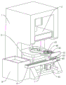
FIG. 1 is a schematic diagram of the structure of the present utility model;
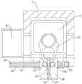
FIG. 2 is a schematic view of the present utility model in a top-down configuration;
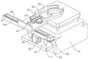
FIG. 3 is a schematic view of a servo motor and a clamping block according to an embodiment of the present utility model;
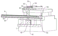
FIG. 4 is a schematic cross-sectional view of a screw according to an embodiment of the present utility model.
The reference numerals in the figures illustrate:
1. a housing; 2. a presser body; 3. a work table; 41. a fixing plate; 42. a cylinder; 43. fixing the hollow rod; 44. a screw; 45. a moving block; 46. a connecting plate; 51. an electric telescopic rod; 52. a toothed bar; 53. a first incomplete gear; 54. a second incomplete gear; 55. a clamping block; 6. a limiting plate; 7. supporting the telescopic rod; 81. placing a plate; 82. a servo motor; 9. placing a box; 10. and (5) reinforcing the block.
Detailed Description
The technical solutions in the embodiments of the present utility model will be clearly and completely described below with reference to the drawings in the embodiments of the present utility model. It is apparent that the described embodiments are only some embodiments of the present utility model, not all embodiments, and that all other embodiments obtained by persons of ordinary skill in the art without making creative efforts based on the embodiments in the present utility model are within the protection scope of the present utility model.
In the description of the present utility model, it should be noted that the positional or positional relationship indicated by the terms such as "upper", "lower", "inner", "outer", "top/bottom", etc. are based on the positional or positional relationship shown in the drawings, are merely for convenience of describing the present utility model and simplifying the description, and do not indicate or imply that the apparatus or elements referred to must have a specific orientation, be constructed and operated in a specific orientation, and thus should not be construed as limiting the present utility model. Furthermore, the terms "first," "second," and the like, are used for descriptive purposes only and are not to be construed as indicating or implying relative importance.
In the description of the present utility model, it should be noted that, unless explicitly specified and limited otherwise, the terms "mounted," "configured to," "engaged with," "connected to," and the like are to be construed broadly, and may be either fixedly connected, detachably connected, or integrally connected, for example; the mechanical connection and the electrical connection can be adopted; can be directly connected or indirectly connected through an intermediate medium, and can be communication between two elements. The specific meaning of the above terms in the present utility model will be understood in specific cases by those of ordinary skill in the art.
Examples:
referring to fig. 1-4, a closed automatic blanking press includes a casing 1, a presser body 2 and a workbench 3, wherein the presser body 2 and the workbench 3 are both disposed inside the casing 1, the casing 1 can mount and connect the presser body 2 and the workbench 3, so that the presser body 2 and the workbench 3 can be used smoothly, the presser body 2 can extrude parts to be processed on the upper side of the workbench 3, meanwhile, the casing 1, the presser body 2 and the workbench 3 can form an important part in the closed pressing press body, a moving mechanism and a driving mechanism are disposed on one side of the workbench 3, a grabbing mechanism is disposed on the upper side of the workbench 3, and the workbench 3 can connect the moving mechanism and the driving mechanism to a certain extent and enable the moving mechanism and the driving mechanism to be used smoothly.
Specifically, the moving mechanism includes fixed plate 41 of fixed connection in workstation 3 one side, fixed plate 41's upside fixedly connected with cylinder 42, the output fixedly connected with fixed hollow rod 43 of cylinder 42, workstation 3 accessible fixed plate 41 plays the effect of installation and fixed to cylinder 42, and cylinder 42 then accessible fixed hollow rod 43, the operation of cylinder 42 accessible self drives fixed hollow rod 43 simultaneously and reciprocates, fixed hollow rod 43's inside sliding connection has movable block 45, fixed hollow rod 43's inside rotation is connected with screw 44, and movable block 45 threaded connection is in the outside of screw 44, fixed hollow rod 43 can play the effect of connecting and installing screw 44 and movable block 45, and make screw 44 can smooth rotation, movable block 45 also can be stable slide in fixed hollow rod 43's inside, fixed hollow rod 43 can play the limiting effect simultaneously to movable block 45, this makes when screw 44 is rotating, the accessible fixed hollow rod 43 carries out the spacing of movable block 45, drive movable block 45 and moves, movable block 45's upside fixedly connected with connecting plate 46, movable block 45 can play the effect of connecting plate 46 when rotatable, movable block 46 can be moved together, and movable block 46 can be moved together through the fixed connection plate 46.
Specifically, snatch mechanism includes electric telescopic handle 51 of fixed connection in connecting plate 46 one side, and connecting plate 46 can play the installation and fixed effect to electric telescopic handle 51 for electric telescopic handle 51 can firmly, smooth use, and electric telescopic handle 51's one end fixedly connected with ratch 52, electric telescopic handle 51 accessible self flexible drives ratch 52 and removes, and electric telescopic handle 51 can select different models according to actual conditions simultaneously, for example: S-22N, the upper side of connecting plate 46 rotates and is connected with first incomplete gear 53 and second incomplete gear 54, and first incomplete gear 53 and second incomplete gear 54 all mesh with rack 52, connecting plate 46 still can play the effect of installation and connection to second incomplete gear 54 and first incomplete gear 53, and make second incomplete gear 54 and first incomplete gear 53 can smoothly rotate, simultaneously when rack 52 moves because of the flexible of electric telescopic handle 51, can drive first incomplete gear 53 and second incomplete gear 54 and rotate, the outside of first incomplete gear 53 and second incomplete gear 54 all fixedly connected with grip block 55, first incomplete gear 53 and second incomplete gear 54 can drive two grip blocks 55 and rotate in the direction that is close to each other or keep away from each other when rotatory, simultaneously when two grip blocks 55 move to the direction that is close to each other after a certain distance, can carry out the mechanism that the work platform 3 upside needs the unloading, simultaneously moving mechanism is in use, can drive two grip blocks 55 through the grip block 55 together, thereby realize that the part is held together to the work platform 3 when the moving mechanism is used, the part is held together to two grip blocks 55.
Specifically, actuating mechanism includes that fixed connection places board 81 in fixed hollow bar 43 one side, the upside fixedly connected with servo motor 82 of placing board 81, servo motor 82's output shaft runs through and places board 81, place the output shaft of board 81 and pass through fixed connection between shaft coupling and the screw rod 44, fixed hollow bar 43 accessible is placed board 81 and is played the effect of fixed and installation to servo motor 82, and servo motor 82 is when the function, then the accessible is connected with screw rod 44 by oneself, drive screw rod 44 and rotate, thereby make the staff when needs rotate screw rod 44, can be more convenient, light, and make actuating mechanism, the movable block 45 among the drive moving mechanism that can be smooth carries out smooth, stable removal.
Specifically, the upside fixedly connected with of fixed plate 41 supports telescopic link 7, support fixed connection between telescopic link 7's the upper end and the fixed hollow rod 43, fixed plate 41 can install, fix support telescopic link 7, and support telescopic link 7 then accessible itself and fixed plate 41 and the relation of connection between fixed hollow rod 43 play certain support and spacing effect, make fixed hollow rod 43 when carrying out the oscilaltion through cylinder 42, can be more stable, smooth, be difficult for taking place the skew, rock or take place the cracked condition between the cylinder 42, support telescopic link 7 comprises first telescopic link and second telescopic link, first telescopic link activity grafting is in the inside of second telescopic link, this makes support telescopic link 7 when using, can be smooth and stable play support and reinforcement effect to fixed hollow rod 43, flexible difficult emergence is unable to take place the condition of supporting the effect because of oneself can't smooth and take place unable normal.
Specifically, the upside fixedly connected with of connecting plate 46 consolidates piece 10, consolidates piece 10 fixed connection in the outside of electric telescopic handle 51, and connecting plate 46 can play the effect of connecting to consolidate piece 10, and consolidate the connection between piece 10 accessible itself and the connecting plate 46, play the effect of consolidating electric telescopic handle 51 to make electric telescopic handle 51 be difficult for taking place to fall down, circumstances such as slope when using, increased electric telescopic handle 51 stability when using.
Specifically, the inside fixedly connected with limiting plate 6 of fixed hollow bar 43, limiting plate 6 sets up in the outside of screw rod 44, and movable block 45 sliding connection is in the outside of limiting plate 6, one side fixedly connected with of casing 1 places case 9, limiting plate 6 can play further spacing effect to movable block 45 for movable block 45 is when removing through the rotation of screw rod 44, is difficult for sending the condition such as slope, rocks, and places the setting of case 9, then can play temporary depositing effect to the part after the unloading, makes things convenient for follow-up staff to unify the processing of part that the processing was good.
The working principle and the using flow of the utility model are as follows: when the device is used, a worker can place a part to be processed on the upper side of the workbench 3, and start the presser body 2 to process and extrude the part on the upper side of the workbench 3, after the part is extruded, the worker can start the servo motor 82, the servo motor 82 drives the fixed hollow rod 43 to rotate through the operation of the worker, at the moment, the fixed hollow rod 43 drives the movable block 45 to move towards the direction close to the workbench 3 through the rotation of the worker, after the two clamping blocks 55 move to the upper side of the part, the worker can start the electric telescopic rod 51, the electric telescopic rod 51 drives the toothed rod 52 to move through the expansion of the worker, and the toothed rod 52 can drive the two clamping blocks 55 to move towards the opposite direction through the meshing of the worker and the first incomplete gear 53 and the second incomplete gear 54 during the movement, when the two clamping blocks 55 move a certain distance, a worker can start the air cylinder 42, at this time, the air cylinder 42 drives the fixed hollow rod 43, the moving block 45, the connecting plate 46 and the two clamping blocks 55 to move downwards, and after the two clamping blocks 55 move to the outer side of the part, the worker can reversely start the electric telescopic rod 51, at this time, the electric telescopic rod 51 drives the two clamping blocks 55 to clamp the machined part through the toothed rod 52, the first incomplete gear 53 and the second incomplete gear 54, after the two clamping blocks 55 clamp the machined part, the air cylinder 42 is reversely started, at this time, the air cylinder 42 removes the machined part from the upper side of the workbench 3 through the fixed hollow rod 43, the moving block 45, the connecting plate 46 and the two moving blocks 45.
After the above operation is completed, the operator can reversely start the servo motor 82, at this time, the servo motor 82 drives the screw rod 44 to reversely rotate, the screw rod 44 also drives the moving block 45 to move along the direction far away from the workbench 3 through limiting the moving block 45, the connecting plate 46, the two clamping blocks 55 and the processed parts by the fixed hollow rod 43, after the two clamping blocks 55 drive the parts to move to the upper side of the placing box 9, the operator can stop the operation of the servo motor 82, and start the air cylinder 42 again, so that the air cylinder 42 drives the fixed hollow rod 43, the connecting plate 46 and the parts clamped by the two clamping blocks 55 to move downwards together, after the parts move downwards to a certain distance, the operator can stop the operation of the air cylinder 42, and start the electric telescopic rod 51 again, at this time, the electric telescopic rod 51 can drive the first incomplete gear 53 and the second incomplete gear 54 to rotate through the movement of the toothed bar 52, and the rotation of the first incomplete gear 53 and the second incomplete gear 54 at this time drives the two clamping blocks 55 to move in opposite directions again, at this time, the parts can fall into the placing box 9 due to the loss of the clamping of the two clamping blocks 55, and can be temporarily collected and stored by the placing box 9, and at this time, the automatic blanking of the closed type pressing machine can be completed, so that the problem that when a worker needs to manufacture and process a plurality of parts, the workload of the worker can be increased, the tired feeling of the worker is increased, and the speed of the worker for taking the parts can be gradually slowed down, and the blanking efficiency of the closed type pressing machine is reduced can be solved.
The foregoing is only a preferred embodiment of the present utility model, but the scope of the present utility model is not limited thereto, and any person skilled in the art, who is within the scope of the present utility model, should make equivalent substitutions or modifications according to the technical solution and the modified concept thereof, within the scope of the present utility model.
Claims (7)
1. The utility model provides a press of automatic unloading of closed, includes casing (1), pushes down ware body (2) and workstation (3), its characterized in that: the pressing device comprises a pressing device body (2) and a workbench (3), wherein the pressing device body (2) and the workbench (3) are arranged in a shell (1), a moving mechanism and a driving mechanism are arranged on one side of the workbench (3), and a grabbing mechanism is arranged on the upper side of the workbench (3); the moving mechanism comprises a fixed plate (41) fixedly connected to one side of the workbench (3), an air cylinder (42) is fixedly connected to the upper side of the fixed plate (41), a fixed hollow rod (43) is fixedly connected to the output end of the air cylinder (42), a moving block (45) is slidably connected to the inside of the fixed hollow rod (43), a screw (44) is rotatably connected to the inside of the fixed hollow rod (43), the moving block (45) is in threaded connection with the outer side of the screw (44), and a connecting plate (46) is fixedly connected to the upper side of the moving block (45).
2. A closed automatic blanking press according to claim 1, characterized in that: the grabbing mechanism comprises an electric telescopic rod (51) fixedly connected to one side of the connecting plate (46), one end of the electric telescopic rod (51) is fixedly connected with a toothed bar (52), a first incomplete gear (53) and a second incomplete gear (54) are rotatably connected to the upper side of the connecting plate (46), the first incomplete gear (53) and the second incomplete gear (54) are meshed with the toothed bar (52), and clamping blocks (55) are fixedly connected to the outer sides of the first incomplete gear (53) and the second incomplete gear (54).
3. A closed automatic blanking press according to claim 1, characterized in that: the driving mechanism comprises a placing plate (81) fixedly connected to one side of the fixed hollow rod (43), a servo motor (82) is fixedly connected to the upper side of the placing plate (81), an output shaft of the servo motor (82) penetrates through the placing plate (81), and an output shaft of the placing plate (81) is fixedly connected with the screw rod (44) through a coupler.
4. A closed automatic blanking press according to claim 1, characterized in that: the upper side of the fixed plate (41) is fixedly connected with a supporting telescopic rod (7), and the upper end of the supporting telescopic rod (7) is fixedly connected with the fixed hollow rod (43).
5. The closed automatic blanking press according to claim 4, wherein: the support telescopic rod (7) consists of a first telescopic rod and a second telescopic rod, and the first telescopic rod is movably inserted into the second telescopic rod.
6. A closed automatic blanking press according to claim 2, characterized in that: the upper side of the connecting plate (46) is fixedly connected with a reinforcing block (10), and the reinforcing block (10) is fixedly connected to the outer side of the electric telescopic rod (51).
7. A closed automatic blanking press according to claim 1, characterized in that: the inside fixedly connected with limiting plate (6) of fixed hollow pole (43), limiting plate (6) set up the outside of screw rod (44), just movable block (45) sliding connection is in the outside of limiting plate (6), one side fixedly connected with of casing (1) places case (9).
Priority Applications (1)
| Application Number | Priority Date | Filing Date | Title |
|---|---|---|---|
| CN202223105999.5U CN219007167U (en) | 2022-11-23 | 2022-11-23 | Closed automatic blanking press |
Applications Claiming Priority (1)
| Application Number | Priority Date | Filing Date | Title |
|---|---|---|---|
| CN202223105999.5U CN219007167U (en) | 2022-11-23 | 2022-11-23 | Closed automatic blanking press |
Publications (1)
| Publication Number | Publication Date |
|---|---|
| CN219007167U true CN219007167U (en) | 2023-05-12 |
Family
ID=86237894
Family Applications (1)
| Application Number | Title | Priority Date | Filing Date |
|---|---|---|---|
| CN202223105999.5U Active CN219007167U (en) | 2022-11-23 | 2022-11-23 | Closed automatic blanking press |
Country Status (1)
| Country | Link |
|---|---|
| CN (1) | CN219007167U (en) |
-
2022
- 2022-11-23 CN CN202223105999.5U patent/CN219007167U/en active Active
Similar Documents
| Publication | Publication Date | Title |
|---|---|---|
| CN219007167U (en) | Closed automatic blanking press | |
| CN203365135U (en) | Speed changer performance testing workbench | |
| CN116833768A (en) | Multi-station rotary combined sheet metal machine tool | |
| CN216990098U (en) | Four-axis cutting equipment | |
| CN112775225B (en) | Forming device of tower crane standard festival dysmorphism platform support frame | |
| CN210208257U (en) | A side cut device for making hydraulic pressure car web structure | |
| CN213320347U (en) | Full-automatic glass fiber precision cutting saw | |
| CN220837724U (en) | Safe type high-efficient reinforcing bar cutting equipment for construction | |
| CN215616669U (en) | Pneumatic gear type multi-station clamp | |
| CN218487253U (en) | Air conditioner accessory processing perforating device | |
| CN215658846U (en) | Special jig for manufacturing precision machinery | |
| CN220461888U (en) | Screw processing side cut device | |
| CN216096624U (en) | Paster cutting device for garden tool | |
| CN220719602U (en) | Punching mechanism and punching machine thereof | |
| CN217141822U (en) | Utmost point ear bending device of lithium cell | |
| CN215925339U (en) | Ultrasonic embossing machine with intelligent protection function | |
| CN216502680U (en) | Punching and pressing mechanism for punching and shearing machine equipment | |
| CN214683990U (en) | Automatic high-efficient apparatus for producing of safety hook | |
| CN212944924U (en) | Automatic pipe bending machine with punching function | |
| CN217044868U (en) | High-efficient double-end saw is used in door and window production | |
| CN218192872U (en) | Cutting die is used in production of car fastener | |
| CN220946067U (en) | Cutting device is used in building block production | |
| CN212795254U (en) | Switching mechanism of die cutting machine template | |
| CN216263164U (en) | Bending mechanism for ignition needle production | |
| CN220942895U (en) | Clamping mechanism for automatic punching flanging machine |
Legal Events
| Date | Code | Title | Description |
|---|---|---|---|
| GR01 | Patent grant | ||
| GR01 | Patent grant |