CN219006801U - Turnover type functional frame device for injection mold production - Google Patents
Turnover type functional frame device for injection mold production Download PDFInfo
- Publication number
- CN219006801U CN219006801U CN202223529798.8U CN202223529798U CN219006801U CN 219006801 U CN219006801 U CN 219006801U CN 202223529798 U CN202223529798 U CN 202223529798U CN 219006801 U CN219006801 U CN 219006801U
- Authority
- CN
- China
- Prior art keywords
- support
- die holder
- type function
- sides
- rotary driving
- Prior art date
- Legal status (The legal status is an assumption and is not a legal conclusion. Google has not performed a legal analysis and makes no representation as to the accuracy of the status listed.)
- Active
Links
Images


Abstract
The utility model discloses a turnover type functional frame device for injection mold production, which comprises a first support, a mold base, a turnover mechanism and a mounting frame, wherein a second support is arranged on one side of the first support, the top between the first support and the second support is provided with the turnover mechanism, the mold base is placed on the top of the turnover mechanism, fixing lugs are fixed on two sides of the turnover mechanism, the mounting frame is arranged on the top of the first support and the top of the second support through rotating shafts, the mounting frame is clamped on the fixing lugs, a first rotary driving mechanism is fixed at the bottom end of one side of the first support, and the output end of the first rotary driving mechanism is connected with the rotating shafts through belt pulley mechanisms. According to the utility model, the first bracket, the second bracket, the first rotary driving mechanism, the rotating shaft, the turnover mechanism, the mounting rack, the screw, the pressing plate, the die holder and the fixing lug are arranged, so that the die is reversely buckled after being molded, and the demolding is facilitated.
Description
Technical Field
The utility model relates to the technical field of injection molding function frames, in particular to a turnover type function frame device for injection mold production.
Background
Injection molding is a method for producing and modeling industrial products, and is characterized in that molten plastic is firstly added into a mold base, and the molten plastic in the mold is gradually and uniformly coated and fused and adhered on the whole surface of a mold cavity under the action of gravity and heat energy, and is molded into a required shape.
1. When the liquid plastic is injected into the die holder, the die holder needs to be horizontally placed on the frame body device, the common frame body does not have the overturning function, and the die holder is not easy to take out from the die cavity after being molded, so that the die is inconvenient to demould; 2. the fixing between the die holder and the frame body usually needs to be connected by bolts, which is not beneficial to the installation and the disassembly of the die holder, and the operation is inconvenient when the die holder needs to be replaced.
Disclosure of Invention
The utility model aims to provide a turnover type functional frame device for producing an injection mold, which is used for solving the problems in the background technology.
In order to achieve the above purpose, the present utility model provides the following technical solutions: the utility model provides a turnover type function frame device for injection mold production, includes first support, die holder, tilting mechanism and mounting bracket, one side of first support is provided with the second support, just the top between first support and the second support is provided with tilting mechanism, the die holder has been placed at tilting mechanism's top, just tilting mechanism's both sides all are fixed with the fixed ear, the top of first support and second support all is provided with the mounting bracket through the pivot, just the mounting bracket centre gripping is on the fixed ear, the bottom mounting of first support one side has first rotary driving mechanism, just the output of first rotary driving mechanism passes through belt pulley mechanism and is connected with the pivot.
Preferably, a supporting plate is fixed at the bottom between the first bracket and the second bracket, and a receiving groove is arranged at the top end of the supporting plate.
Preferably, the both sides at tilting mechanism top all set up the recess, just the inside of recess all is provided with two-way lead screw, the both ends of two-way lead screw all overlap and are equipped with the movable sleeve, just the top of movable sleeve all is provided with the holder through the movable frame.
Preferably, a driving chamber is arranged on one side of the turnover mechanism, a second rotary driving mechanism is arranged in the driving chamber, and the output end of the second rotary driving mechanism is connected with 2 groups of bidirectional screw rods through a belt pulley mechanism.
Preferably, slide rails are arranged on two sides of the bottom of the receiving groove, and slide grooves matched with the slide rails are arranged on two sides of the top of the supporting plate.
Preferably, the clamping pieces are clamped at two sides of the die holder, and the clamping pieces are distributed symmetrically left and right relative to the die holder.
Preferably, clamping grooves are uniformly formed in one side, close to the die holder, of the clamping piece, and clamping columns matched with the clamping grooves are uniformly distributed on two sides of the die holder.
Preferably, guide rods are arranged at the bottom ends of the grooves, and the bottom ends of the movable sleeves are sleeved with the guide rods in a sliding manner through the guide sleeves.
Preferably, the top of mounting bracket all is passed there is the screw rod, just the bottom of screw rod all is provided with the clamp plate, the bottom of clamp plate all is connected with the fixed ear.
Compared with the prior art, the utility model has the beneficial effects that:
(1) This convertible function frame device of injection mold production usefulness is through installing first support, second support, first rotary driving mechanism, pivot, tilting mechanism, mounting bracket, screw rod, clamp plate, die holder and fixed ear, drive the clamp plate through the rotation screw rod and move down, press from both sides the fixed ear tightly, the die holder is disposed at tilting mechanism top, afterwards first rotary driving mechanism passes through belt pulley mechanism and drives the pivot rotation for the mounting bracket rotates, drives tilting mechanism and die holder and rotates downwards, does benefit to the back-off with the mould after the mould shaping, the drawing of patterns of being convenient for.
(2) This upset formula function frame device that injection mold production was used is through installing backup pad, receiving silo, slide rail and spout for the die holder after the upset is located and receives the silo top, and in the mould drawing of patterns got into receiving the silo, the accessible is taken out receiving the silo in the slide rail that slides afterwards, is convenient for take out the mould.
(3) This convertible function frame device of injection mold production usefulness is through installing recess, two-way lead screw, second rotary driving mechanism, holder, draw-in groove and card post, and second rotary driving mechanism accessible belt pulley mechanism drives two-way lead screw and rotates for the movable sleeve is close to each other, makes the draw-in groove on the holder be connected with the card post of die holder both sides, can press from both sides tight spacing with the die holder of different specifications, conveniently changes the die holder.
Drawings
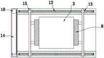
FIG. 1 is a schematic elevational view of the present utility model;
FIG. 2 is a schematic cross-sectional view of the turnover mechanism of the present utility model;
FIG. 3 is a schematic top view of the turnover mechanism of the present utility model;
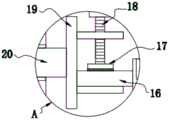
FIG. 4 is an enlarged cross-sectional view of the structure of FIG. 1A according to the present utility model;
fig. 5 is an enlarged sectional view of fig. 1B according to the present utility model.
In the figure: 1. a first rotary drive mechanism; 2. a first bracket; 3. a die holder; 4. a turnover mechanism; 5. a second bracket; 6. a receiving groove; 7. a support plate; 8. a clamping member; 801. a clamping column; 9. a clamping groove; 10. a second rotary drive mechanism; 11. a groove; 12. a two-way screw rod; 13. a movable sleeve; 14. a driving chamber; 15. a movable frame; 16. a fixed ear; 17. a pressing plate; 18. a screw; 19. a mounting frame; 20. a rotating shaft; 21. a slide rail; 22. and a sliding groove.
Detailed Description
The technical solutions in the embodiments of the present utility model will be clearly and completely described below with reference to the accompanying drawings in the embodiments of the present utility model. All other embodiments, which can be made by those skilled in the art based on the embodiments of the utility model without making any inventive effort, are intended to be within the scope of the utility model.
Referring to fig. 1-5, an embodiment of the present utility model is provided: the turnover type functional frame device for producing the injection mold comprises a first bracket 2, a mold base 3, a turnover mechanism 4 and a mounting frame 19, wherein a second bracket 5 is arranged on one side of the first bracket 2, the turnover mechanism 4 is arranged at the top end between the first bracket 2 and the second bracket 5, and the mold base 3 is arranged at the top of the turnover mechanism 4;
the two sides of the turnover mechanism 4 are respectively fixed with a fixed lug 16, the tops of the first bracket 2 and the second bracket 5 are respectively provided with a mounting frame 19 through a rotating shaft 20, and the mounting frames 19 are clamped on the fixed lugs 16;
the top of the mounting frame 19 is provided with a screw 18 in a penetrating way, the bottom end of the screw 18 is provided with a pressing plate 17, and the bottom end of the pressing plate 17 is connected with the fixed lugs 16;
the pressing plate 17 is driven to move downwards by rotating the screw rod 18, the fixing lug 16 is clamped, and the die holder 3 is arranged at the top of the turnover mechanism 4;
grooves 11 are formed in two sides of the top of the turnover mechanism 4, a bidirectional screw rod 12 is arranged in the grooves 11, movable sleeves 13 are sleeved at two ends of the bidirectional screw rod 12, and clamping pieces 8 are arranged at the tops of the movable sleeves 13 through movable frames 15;
one side of the turnover mechanism 4 is provided with a driving chamber 14, a second rotary driving mechanism 10 is arranged in the driving chamber 14, and the output end of the second rotary driving mechanism 10 is connected with 2 groups of bidirectional screw rods 12 through a belt pulley mechanism;
the second rotary driving mechanism 10 can drive the bidirectional screw rod 12 to rotate through a belt pulley mechanism, so that the movable sleeves 13 are close to each other;
clamping pieces 8 are clamped on two sides of the die holder 3, the clamping pieces 8 are distributed symmetrically about the die holder 3, clamping grooves 9 are uniformly formed in one side, close to the die holder 3, of the clamping pieces 8, and clamping columns 801 matched with the clamping grooves 9 are uniformly distributed on two sides of the die holder 3;
the clamping grooves 9 on the clamping piece 8 are connected with clamping columns 801 on two sides of the die holder 3, so that the die holders 3 with different specifications can be clamped and limited;
the bottom end inside the groove 11 is provided with a guide rod, and the bottom end of the movable sleeve 13 is in sliding sleeve joint with the guide rod through the guide sleeve, so that the movable sleeve 13 is guided and limited;
the bottom end of one side of the first bracket 2 is fixed with a first rotary driving mechanism 1, and the output end of the first rotary driving mechanism 1 is connected with a rotating shaft 20 through a belt pulley mechanism;
the molten raw material is injected into the die holder 3, and after cooling forming, the first rotary driving mechanism 1 drives the rotating shaft 20 to rotate through the belt pulley mechanism, so that the mounting frame 19 rotates to drive the turnover mechanism 4 and the die holder 3 to rotate downwards, thereby facilitating the back-off of the die after forming the die and facilitating the demoulding;
a supporting plate 7 is fixed at the bottom between the first bracket 2 and the second bracket 5, a receiving groove 6 is arranged at the top end of the supporting plate 7, and the die enters the receiving groove 6 after being demolded;
slide rails 21 are arranged on two sides of the bottom of the receiving chute 6, slide grooves 22 matched with the slide rails 21 are arranged on two sides of the top of the supporting plate 7, and the receiving chute 6 can be pulled out by sliding the slide rails 21 in the slide grooves 22, so that the die can be taken out conveniently;
the specific model specifications of the first rotary driving mechanism 1 and the second rotary driving mechanism 10 need to be determined according to the model selection calculation of the specification parameters and the like of the device, and the model selection calculation method is the prior art, so detailed description is omitted.
Working principle: when the die holder is used, the second rotary driving mechanism 10 can drive the bidirectional screw rod 12 to rotate through the belt pulley mechanism, the movable sleeves 13 are close to each other, clamping grooves 9 on the clamping piece 8 are connected with clamping columns 801 on two sides of the die holder 3, the die holder 3 with different specifications can be clamped and limited, molten raw materials are injected into the die holder 3, the first rotary driving mechanism 1 drives the rotary shaft 20 to rotate through the belt pulley mechanism after cooling forming, the mounting frame 19 is enabled to rotate, the turnover mechanism 4 and the die holder 3 are driven to rotate downwards, die back-off is facilitated after die forming, die stripping is facilitated, the die is conveniently carried out, the die is released, the die is then discharged from the die receiving groove 6 through sliding rails 21 in the sliding grooves 22, and the die is conveniently taken out.
Claims (9)
1. The utility model provides a turnover type function frame device for injection mold production, its characterized in that, including first support (2), die holder (3), tilting mechanism (4) and mounting bracket (19), one side of first support (2) is provided with second support (5), just the top between first support (2) and second support (5) is provided with tilting mechanism (4), die holder (3) have been placed at the top of tilting mechanism (4), just the both sides of tilting mechanism (4) all are fixed with fixed ear (16), the top of first support (2) and second support (5) all is provided with mounting bracket (19) through pivot (20), just mounting bracket (19) centre gripping is on fixed ear (16), the bottom of first support (2) one side is fixed with first rotary driving mechanism (1), just the output of first rotary driving mechanism (1) is connected with pivot (20) through belt pulley mechanism.
2. The turnover type function frame device for producing injection molds according to claim 1, wherein: a supporting plate (7) is fixed at the bottom between the first bracket (2) and the second bracket (5), and a receiving groove (6) is arranged at the top end of the supporting plate (7).
3. The turnover type function frame device for producing injection molds according to claim 1, wherein: the two sides of tilting mechanism (4) top all offer recess (11), just the inside of recess (11) all is provided with two-way lead screw (12), the both ends of two-way lead screw (12) all overlap and are equipped with movable sleeve (13), just the top of movable sleeve (13) all is provided with clamping piece (8) through movable frame (15).
4. A roll-over type function rack device for injection mold production according to claim 3, wherein: one side of the turnover mechanism (4) is provided with a driving chamber (14), a second rotary driving mechanism (10) is arranged in the driving chamber (14), and the output end of the second rotary driving mechanism (10) is connected with 2 groups of bidirectional screw rods (12) through a belt pulley mechanism.
5. The turnover type function frame device for producing injection molds according to claim 2, wherein: slide rails (21) are arranged on two sides of the bottom of the receiving groove (6), and slide grooves (22) matched with the slide rails (21) are formed on two sides of the top of the supporting plate (7).
6. A roll-over type function rack device for injection mold production according to claim 3, wherein: the clamping pieces (8) are clamped on two sides of the die holder (3), and the clamping pieces (8) are distributed symmetrically left and right relative to the die holder (3).
7. A roll-over type function rack device for injection mold production according to claim 3, wherein: clamping grooves (9) are uniformly formed in one side, close to the die holder (3), of the clamping piece (8), and clamping columns (801) matched with the clamping grooves (9) are uniformly distributed on two sides of the die holder (3).
8. A roll-over type function rack device for injection mold production according to claim 3, wherein: the bottom inside recess (11) all is provided with the guide bar, the bottom of movable sleeve (13) all cup joints with the guide bar slip through the uide bushing.
9. The turnover type function frame device for producing injection molds according to claim 1, wherein: the top of mounting bracket (19) all is passed there is screw rod (18), just the bottom of screw rod (18) all is provided with clamp plate (17), the bottom of clamp plate (17) all is connected with fixed ear (16).
Priority Applications (1)
| Application Number | Priority Date | Filing Date | Title |
|---|---|---|---|
| CN202223529798.8U CN219006801U (en) | 2022-12-27 | 2022-12-27 | Turnover type functional frame device for injection mold production |
Applications Claiming Priority (1)
| Application Number | Priority Date | Filing Date | Title |
|---|---|---|---|
| CN202223529798.8U CN219006801U (en) | 2022-12-27 | 2022-12-27 | Turnover type functional frame device for injection mold production |
Publications (1)
| Publication Number | Publication Date |
|---|---|
| CN219006801U true CN219006801U (en) | 2023-05-12 |
Family
ID=86248650
Family Applications (1)
| Application Number | Title | Priority Date | Filing Date |
|---|---|---|---|
| CN202223529798.8U Active CN219006801U (en) | 2022-12-27 | 2022-12-27 | Turnover type functional frame device for injection mold production |
Country Status (1)
| Country | Link |
|---|---|
| CN (1) | CN219006801U (en) |
-
2022
- 2022-12-27 CN CN202223529798.8U patent/CN219006801U/en active Active
Similar Documents
| Publication | Publication Date | Title |
|---|---|---|
| CN213260726U (en) | Multistation injection molding machine for polymer rubber and plastic | |
| CN210139593U (en) | Injection mold ejection mechanism capable of achieving rapid demolding | |
| CN106584774A (en) | Injection mold for forming assembly | |
| CN113172826B (en) | Integrated injection mold | |
| CN219006801U (en) | Turnover type functional frame device for injection mold production | |
| CN209534045U (en) | A kind of plastic mould with cutting function | |
| CN219618422U (en) | Injection molding mould is used in toy production convenient to drawing of patterns | |
| CN212385915U (en) | Injection mold for injection molding of automobile parts and convenient demolding | |
| CN211566712U (en) | Full-automatic precise micro plastic structure processing equipment | |
| CN109262945B (en) | Operation method of automatic shaping and outputting integrated injection molding machine | |
| CN113733457A (en) | Automobile door inner guard plate injection molding device convenient for raw material injection and injection molding method thereof | |
| CN210308728U (en) | Automatic feeding device of continuous die | |
| CN107901344B (en) | Injection mold capable of rapidly and efficiently demolding and injection molding method thereof | |
| CN216182508U (en) | Energy-efficient PVC material injection moulding device | |
| CN218985640U (en) | Leak-proof injection molding machine | |
| CN214491384U (en) | Accurate miniature environmental protection material shell structure of moulding plastics | |
| CN212097345U (en) | Hot runner injection mold of outside oblique kicking block structure of loosing core | |
| CN219076316U (en) | Rubber product forming die | |
| CN213767031U (en) | Automatic mold locking device of injection molding machine | |
| CN216329772U (en) | Injection mold extension ejection mechanism | |
| CN220242258U (en) | Plastic forming die with built-in hot runner | |
| CN220784744U (en) | Injection mold for foam product | |
| CN216732836U (en) | But cell-phone shell injection mold of rapid demoulding | |
| CN217196657U (en) | Molding equipment convenient to adjust | |
| CN217573826U (en) | Injection mold convenient for stripping |
Legal Events
| Date | Code | Title | Description |
|---|---|---|---|
| GR01 | Patent grant | ||
| GR01 | Patent grant |