CN219006269U - Positioning pipe cutting machine for insulating sleeve - Google Patents
Positioning pipe cutting machine for insulating sleeve Download PDFInfo
- Publication number
- CN219006269U CN219006269U CN202223315504.1U CN202223315504U CN219006269U CN 219006269 U CN219006269 U CN 219006269U CN 202223315504 U CN202223315504 U CN 202223315504U CN 219006269 U CN219006269 U CN 219006269U
- Authority
- CN
- China
- Prior art keywords
- fixed
- cutting
- fixed frame
- electric telescopic
- cutting case
- Prior art date
- Legal status (The legal status is an assumption and is not a legal conclusion. Google has not performed a legal analysis and makes no representation as to the accuracy of the status listed.)
- Active
Links
Images


Classifications
-
- Y—GENERAL TAGGING OF NEW TECHNOLOGICAL DEVELOPMENTS; GENERAL TAGGING OF CROSS-SECTIONAL TECHNOLOGIES SPANNING OVER SEVERAL SECTIONS OF THE IPC; TECHNICAL SUBJECTS COVERED BY FORMER USPC CROSS-REFERENCE ART COLLECTIONS [XRACs] AND DIGESTS
- Y02—TECHNOLOGIES OR APPLICATIONS FOR MITIGATION OR ADAPTATION AGAINST CLIMATE CHANGE
- Y02P—CLIMATE CHANGE MITIGATION TECHNOLOGIES IN THE PRODUCTION OR PROCESSING OF GOODS
- Y02P70/00—Climate change mitigation technologies in the production process for final industrial or consumer products
- Y02P70/10—Greenhouse gas [GHG] capture, material saving, heat recovery or other energy efficient measures, e.g. motor control, characterised by manufacturing processes, e.g. for rolling metal or metal working
Landscapes
- Sawing (AREA)
Abstract
The utility model relates to the technical field of pipe cutting machines and discloses a positioning pipe cutting machine for an insulating sleeve, which comprises a device body, wherein a cutting box is fixedly arranged on the upper surface of the device body, a pushing mechanism is arranged on the cutting box, the pushing mechanism comprises a first fixed frame, a rotating motor, a rotating gear, a fixed track and a movable toothed plate, the side surface of the first fixed frame is fixedly arranged on one side of the cutting box, and the bottom of the first fixed frame is welded with the upper surface of the device body. This kind of insulating tube is with location pipe cutting machine, the effectual in-service use that has solved, the device is inconvenient to carry out accurate fixed length to tubular product and cuts, and then very big reduction the efficiency of cutting to have the problem of certain limitation when having caused the use of device, can be quick carry out the distance location to it according to required tubular product cutting length in the whole operation process, and then be convenient for cut the tubular product to the fixed length, improved the practicality of device.
Description
Technical Field
The utility model relates to the technical field of pipe cutting machines, in particular to a positioning pipe cutting machine for an insulating sleeve.
Background
Pipe cutting machines, also called pipe cutting devices or pipe cutting equipment, are pipe cutting machines for cutting long pipe fittings into short pipe fittings with required lengths, and the pipe cutting machines are widely used in a plurality of fields because of the advantages of high cutting efficiency, convenient operation and the like.
According to the pipe cutting machine of patent number CN215790179U, the problem that traditional pipe cutting mode generally adopts manual cutting, wastes time and energy, inefficiency when having solved current device in this scheme when using.
At present, the device is inconvenient when using, and the accurate fixed length of advance is cut to the pipe material to inconvenient pair of pipe material simultaneously, and then very big reduction cuts efficiency to the problem that has certain limitation when having caused the use of device, and the device can produce a large amount of piece when cutting, and then lead to the piece to scatter in the device, if unable clearance piece in time, wherein piece can get into cutting tool and pipe cutting machine inside and influence normal operating, and then cause the problem to the device damage, the problem that exists to the device, the utility model provides a positioning pipe cutting machine for insulating sleeve.
Disclosure of Invention
Aiming at the defects of the prior art, the utility model provides a positioning pipe cutting machine for an insulating sleeve, which has the advantages of being capable of rapidly and accurately positioning a pipe to be cut and effectively collecting scraps generated during cutting of a device, and solves the problems in the background art.
The utility model provides the following technical scheme: the utility model provides a positioning pipe cutting machine for insulating sleeve, includes the device body, the last fixed surface of device body installs the cutting case, the cutting case with this is provided with pushing mechanism, pushing mechanism is including first fixed frame, rotation motor, rotation gear, fixed track and removal pinion rack, the side of first fixed frame and one side fixed mounting of cutting case, the welding of the last table of the bottom of first fixed frame and device body, the side of rotation motor and the side fixed mounting of first fixed frame, the output shaft of rotation motor runs through the side of first fixed frame, the inner wall of rotation gear and the one end fixed connection of rotation motor output shaft, the inside bottom fixed mounting of first fixed frame has fixed track, fixed track runs through the side of cutting case.
Preferably, the bottom of cutting case is provided with collection mechanism, collection mechanism is including ventilative net, transmission pipeline, collecting box and fixed case, the surface of ventilative net and the inner wall fixed mounting of cutting case bottom, the one end of transmission pipeline and the bottom fixed connection of cutting case, the bottom of device body is run through to the one end of transmission pipeline, the top of collecting box and the other end fixed connection of transmission pipeline, the top of collecting box is run through to the other end of transmission pipeline, the side fixed mounting of side and collecting box of fixed case.
Preferably, the inner wall sliding connection of fixed track has the removal pinion rack, it runs through one side of cutting case to remove the pinion rack, the one end fixedly connected with of removal pinion rack supports the clamp plate, and supports the bottom of clamp plate and the laminating of the bottom of cutting case inner wall.
Preferably, the top fixed mounting of cutting case has first fixed sleeve axle, the inside of first fixed sleeve axle has cup jointed first electric telescopic handle, and first electric telescopic handle runs through the top of cutting case, the inner wall of first electric telescopic handle is provided with the cutting wheel.
Preferably, the side of fixed incasement wall rotates and is connected with the rotation fan, the inside fixed mounting of collection box side has the filter screen, the side fixed mounting of collection box has first fixed sleeve, the inner wall sliding connection of first fixed sleeve has first electric telescopic handle, and the side of first electric telescopic handle is laminated with the side of collection box.
Preferably, the opposite side fixed mounting of cutting case has the fixed frame of second, the fixed sleeve of top fixed mounting of fixed frame of second has the fixed sleeve of second, the inner wall of fixed sleeve of second has cup jointed the second electric telescopic handle, and the second electric telescopic handle runs through the top of the fixed frame of second, the one end fixed mounting of second electric telescopic handle has the extrusion piece, the bottom and the locating piece laminating of extrusion piece, and the upper surface fixed connection of the bottom device body of locating piece.
Preferably, the top welding of first fixed frame has the extension piece, and the side of extension piece is laminated with one side of cutting case, the inner wall threaded connection of extension piece has fixation nut, and the one end of fixation nut and the inside threaded connection of cutting case one side.
Compared with the prior art, the utility model has the following beneficial effects:
1. the positioning pipe cutting machine for the insulating sleeve is characterized in that when the positioning pipe cutting machine is used, the rotating motor output shaft fixedly installed on the side face of the first fixed frame rotates to drive the rotating gear to rotate, so that the movable toothed plate meshed with the outer surface of the rotating gear is driven to move back and forth in the inner wall of the fixed track, the pressing plate connected with the end part of the movable toothed plate is enabled to move, the pipe is supported and positioned, the length of required cutting is controlled, the problem that the pipe is inconvenient to cut in a precise fixed length manner in the actual use process is effectively solved, the cutting efficiency is greatly reduced, the problem that certain limitation exists in the use process of the device is solved, the pipe can be rapidly positioned in a distance manner according to the required cutting length of the pipe in the whole operation process, the pipe is conveniently cut in a fixed length manner, and the practicability of the device is improved;
2. this insulating boot is with location pipe cutting machine, when using, when the device is cutting tubular product, the effect through the external power source drives the inside rotating fan who rotates the connection of fixed case and rotates, thereby make the inside suction that produces of collecting box, with this follow-up collection that produces when the device is cutting, and store in the inside of collecting box, can carry out recovery processing through pulling the first electric telescopic handle that the collecting box side set up when its inside is pushed to the removal degree, and then with the inside accumulational follow-up of collecting box, the effectual in-service use in-process that has been solved, the device can produce a large amount of fragments when cutting, and then lead to the fragment to scatter in the device, the fragment can get into cutting tool and inside the pipe cutting machine, and then cause the problem of damaging the device, can effectually collect the piece that produces the device operation in the whole operation process, thereby prevent that the piece from getting into the device inside and cause the damage to the device, thereby very big improvement the stability when the device is operated.
Drawings
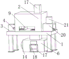
FIG. 1 is a schematic diagram of the overall structure of the device of the present utility model;
FIG. 2 is a schematic side view of the structure of FIG. 1 of the present utility model;
FIG. 3 is a schematic cross-sectional view of FIG. 1 in accordance with the present utility model;
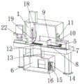
fig. 4 is a schematic rear view of the structure of fig. 1 according to the present utility model.
In the figure: 1. a device body; 2. a cutting box; 3. a first fixing frame; 4. a rotating motor; 5. rotating the gear; 6. a collection box; 7. a fixed rail; 8. moving the toothed plate; 9. a pressing plate; 10. an extension block; 11. a fixing nut; 12. a breathable net; 13. a transmission pipeline; 14. a fixed box; 15. rotating the fan; 16. a filter screen; 17. a first fixed sleeve shaft; 18. a first electric telescopic rod; 19. a cutting wheel; 20. a second fixing frame; 21. a second fixed sleeve shaft; 22. a second electric telescopic rod; 23. extruding a block; 24. and (5) positioning blocks.
Detailed Description
The following description of the embodiments of the present utility model will be made clearly and completely with reference to the accompanying drawings, in which it is apparent that the embodiments described are only some embodiments of the present utility model, but not all embodiments. All other embodiments, which can be made by those skilled in the art based on the embodiments of the utility model without making any inventive effort, are intended to be within the scope of the utility model.
Referring to fig. 1-4, a positioning pipe cutting machine for insulation sleeve, which comprises a device body 1, the upper surface fixed mounting of device body 1 has cutting case 2, this is provided with pushing mechanism with cutting case 2, pushing mechanism is including first fixed frame 3, rotating electrical machines 4, rotating gear 5, fixed track 7 and removal pinion rack 8, the side of first fixed frame 3 and one side fixed mounting of cutting case 2, the bottom of first fixed frame 3 welds with the table of device body 1, the side of rotating electrical machines 4 and the side fixed mounting of first fixed frame 3, the output shaft of rotating electrical machines 4 runs through the side of first fixed frame 3, the inner wall of rotating gear 5 and the one end fixed connection of rotating electrical machines 4 output shaft, the inside bottom fixed mounting of first fixed frame 3 has fixed track 7, fixed track 7 runs through the side of cutting case 2, pushing mechanism can be quick according to required tubular product cutting length carries out the distance location, and then be convenient for cut to the tubular product length, the practicality of device has been improved.
Wherein; the bottom of cutting case 2 is provided with collection mechanism, collection mechanism is including ventilative net 12, transmission pipeline 13, collection box 6 and fixed box 14, the surface of ventilative net 12 and the inner wall fixed mounting of cutting case 2 bottom, the one end of transmission pipeline 13 and the bottom fixed connection of cutting case 2, the bottom of device body 1 is run through to the one end of transmission pipeline 13, the top of collection box 6 and the other end fixed connection of transmission pipeline 13, the top of collection box 6 is run through to the other end of transmission pipeline 13, the side of fixed box 14 and the side fixed mounting of collection box 6, collection mechanism can effectually collect the piece that the device operation was produced, thereby prevent piece entering device inside and cause the damage to the device, thereby very big improvement the stability when the device is operated.
Wherein; the inner wall sliding connection of fixed track 7 has removes pinion rack 8, removes one side that pinion rack 8 runs through cutting case 2, and the one end fixedly connected with of removing pinion rack 8 supports clamp plate 9, and supports the bottom laminating of clamp plate 9 and the bottom of cutting case 2 inner wall, removes pinion rack 8 and removes under the effect of rotation gear 5 to drive and support clamp plate 9 and remove, thereby accomplish and fix a position tubular product length.
Wherein; the top fixed mounting of cutting case 2 has first fixed sleeve 17, and first electric telescopic handle 18 has been cup jointed to the inside of first fixed sleeve 17, and first electric telescopic handle 18 runs through the top of cutting case 2, and the inner wall of first electric telescopic handle 18 is provided with cutting wheel 19, and in the tubular product entering device and after fixed, the lift effect through first electric telescopic handle 18 drives cutting wheel 19 and goes up and down to accomplish and cut tubular product.
Wherein; the side of the inner wall of the fixed box 14 is rotationally connected with a rotary fan 15, a filter screen 16 is fixedly arranged in the side of the collecting box 6, a first fixed sleeve shaft 17 is fixedly arranged on the side of the collecting box 6, a first electric telescopic rod 18 is connected with the inner wall of the first fixed sleeve shaft 17 in a sliding manner, and the side of the first electric telescopic rod 18 is attached to the side of the collecting box 6.
Wherein; the opposite side fixed mounting of cutting case 2 has the fixed frame 20 of second, the fixed sleeve axle 21 of second is fixed at the top fixed mounting of fixed frame 20, the inner wall of the fixed sleeve axle 21 of second has cup jointed second electric telescopic handle 22, and second electric telescopic handle 22 runs through the top of fixed frame 20 of second, the one end fixed mounting of second electric telescopic handle 22 has extrusion piece 23, extrusion piece 23's bottom and locating piece 24 laminating, and the upper surface fixed connection of the bottom device body 1 of locating piece 24, extrusion piece 23 and locating piece 24 can effectually carry out the centre gripping with the tubular product that stretches into in the device fixedly, thereby prevent that tubular product from taking place to rock when cutting.
Wherein; the top welding of first fixed frame 3 has extension piece 10, and the side of extension piece 10 is laminated with one side of cutting case 2, and the inner wall threaded connection of extension piece 10 has fixation nut 11, and the one end of fixation nut 11 and the inside threaded connection of cutting case 2 one side, and extension piece 10 and fixation nut 11 are further fixed to first fixed frame 3 to guarantee the stability of first fixed frame 3 when the device operation.
When the cutting machine is used, the rotation of the output shaft of the rotary motor 4 fixedly installed on the side face of the first fixed frame 3 is firstly used, and then the rotary gear 5 is driven to rotate, so that the movable toothed plate 8 meshed with the outer surface of the rotary gear 5 is driven to move back and forth in the inner wall of the fixed track 7, the pressing plate 9 connected with the end part of the movable toothed plate 8 is enabled to move, the pipe is supported and positioned, and the length of cutting is controlled.
Meanwhile, when the device cuts the pipe, the rotating fan 15 which is rotationally connected inside the fixed box 14 is driven to rotate through the action of an external power source, so that suction is generated inside the collecting box 6, the follow-up generated during cutting of the device is collected, the follow-up generated during cutting is stored inside the collecting box 6, when the inside of the device is pushed to a moving degree, the first electric telescopic rod 18 arranged on the side face of the collecting box 6 can be pulled, and further, the follow-up accumulated inside the collecting box 6 is recycled, so that the resource utilization rate is improved.
It is noted that relational terms such as first and second, and the like are used solely to distinguish one entity or action from another entity or action without necessarily requiring or implying any actual such relationship or order between such entities or actions. Moreover, the terms "comprises," "comprising," or any other variation thereof, are intended to cover a non-exclusive inclusion, such that a process, method, article, or apparatus that comprises a list of elements does not include only those elements but may include other elements not expressly listed or inherent to such process, method, article, or apparatus.
Although embodiments of the present utility model have been shown and described, it will be understood by those skilled in the art that various changes, modifications, substitutions and alterations can be made therein without departing from the principles and spirit of the utility model, the scope of which is defined in the appended claims and their equivalents.
Claims (7)
1. The utility model provides a positioning pipe cutting machine for insulating boot, its characterized in that, including device body (1), the last fixed surface of device body (1) installs cutting case (2), the side that is provided with pushing mechanism with this of cutting case (2), pushing mechanism is including first fixed frame (3), rotation motor (4), rotation gear (5), fixed track (7) and removal pinion rack (8), the side of first fixed frame (3) and one side fixed mounting of cutting case (2), the welding of the last table of the bottom of first fixed frame (3) and device body (1), the side of rotation motor (4) and the side fixed mounting of first fixed frame (3), the output shaft of rotation motor (4) runs through the side of first fixed frame (3), the inner wall of rotation gear (5) and the one end fixed connection of rotation motor (4) output shaft, the inside bottom fixed mounting of first fixed frame (3) has fixed track (7), the side of cutting case (2) is run through to fixed track (7).
2. The positioning pipe cutting machine for insulating sleeves according to claim 1, wherein: the bottom of cutting case (2) is provided with collection mechanism, collection mechanism is including ventilative net (12), transmission pipeline (13), collection box (6) and fixed box (14), the surface of ventilative net (12) and the inner wall fixed mounting of cutting case (2) bottom, the one end of transmission pipeline (13) and the bottom fixed connection of cutting case (2), the bottom of device body (1) is run through to the one end of transmission pipeline (13), the top of collection box (6) and the other end fixed connection of transmission pipeline (13), the top of collection box (6) is run through to the other end of transmission pipeline (13), the side of fixed box (14) and the side fixed mounting of collection box (6).
3. The positioning pipe cutting machine for insulating sleeves according to claim 1, wherein: the inner wall sliding connection of fixed track (7) has removal pinion rack (8), one side of cutting case (2) is run through to removal pinion rack (8), the one end fixedly connected with of removal pinion rack (8) supports clamp plate (9), and supports the bottom of clamp plate (9) and the laminating of the bottom of cutting case (2) inner wall.
4. The positioning pipe cutting machine for insulating sleeves according to claim 1, wherein: the top fixed mounting of cutting case (2) has first fixed sleeve axle (17), the inside of first fixed sleeve axle (17) has cup jointed first electric telescopic handle (18), and the top of cutting case (2) is run through to first electric telescopic handle (18), the inner wall of first electric telescopic handle (18) is provided with cutting wheel (19).
5. The positioning pipe cutting machine for insulating sleeves according to claim 2, wherein: the side of fixed case (14) inner wall rotates and is connected with rotates fan (15), the inside fixed mounting of collection box (6) side has filter screen (16), the side fixed mounting of collection box (6) has first fixed sleeve (17), the inner wall sliding connection of first fixed sleeve (17) has first electric telescopic handle (18), and the side laminating of first electric telescopic handle (18) and the side of collection box (6).
6. The positioning pipe cutting machine for insulating sleeves according to claim 1, wherein: the opposite side fixed mounting of cutting case (2) has second fixed frame (20), the top fixed mounting of second fixed frame (20) has second fixed sleeve (21), the inner wall of second fixed sleeve (21) has cup jointed second electric telescopic handle (22), and the top of second electric telescopic handle (22) run through second fixed frame (20), the one end fixed mounting of second electric telescopic handle (22) has extrusion piece (23), the bottom and the laminating of locating piece (24) of extrusion piece (23), and the upper surface fixed connection of the bottom device body (1) of locating piece (24).
7. The positioning pipe cutting machine for insulating sleeves according to claim 1, wherein: the top welding of first fixed frame (3) has extension piece (10), and the side of extension piece (10) is laminated with one side of cutting case (2), the inner wall threaded connection of extension piece (10) has fixation nut (11), and the inside threaded connection of one end and cutting case (2) one side of fixation nut (11).
Priority Applications (1)
| Application Number | Priority Date | Filing Date | Title |
|---|---|---|---|
| CN202223315504.1U CN219006269U (en) | 2022-12-12 | 2022-12-12 | Positioning pipe cutting machine for insulating sleeve |
Applications Claiming Priority (1)
| Application Number | Priority Date | Filing Date | Title |
|---|---|---|---|
| CN202223315504.1U CN219006269U (en) | 2022-12-12 | 2022-12-12 | Positioning pipe cutting machine for insulating sleeve |
Publications (1)
| Publication Number | Publication Date |
|---|---|
| CN219006269U true CN219006269U (en) | 2023-05-12 |
Family
ID=86238791
Family Applications (1)
| Application Number | Title | Priority Date | Filing Date |
|---|---|---|---|
| CN202223315504.1U Active CN219006269U (en) | 2022-12-12 | 2022-12-12 | Positioning pipe cutting machine for insulating sleeve |
Country Status (1)
| Country | Link |
|---|---|
| CN (1) | CN219006269U (en) |
-
2022
- 2022-12-12 CN CN202223315504.1U patent/CN219006269U/en active Active
Similar Documents
| Publication | Publication Date | Title |
|---|---|---|
| CN219006269U (en) | Positioning pipe cutting machine for insulating sleeve | |
| CN217513931U (en) | Food cutting equipment for food production | |
| CN218614350U (en) | Vibration sword cutting machine convenient to adjust | |
| CN215070839U (en) | Novel processing device for oil field underground test cable | |
| CN212169231U (en) | Hardware slotting equipment with self-cleaning function | |
| CN212329897U (en) | High-efficient finishing device of seamless steel pipe | |
| CN221110904U (en) | Aluminum product cutting circulation feeding equipment | |
| CN221211932U (en) | Crop head machine convenient for fixing pipe | |
| CN214212415U (en) | Section bar cutting device is used in big-arch shelter pipe production | |
| CN220480282U (en) | Perforating device for seamless steel tube processing convenient to clear away sweeps | |
| CN220128955U (en) | Automatic material collecting device of cutting machine | |
| CN217800528U (en) | Electric automatization cutting device | |
| CN220029433U (en) | Environment-friendly multifunctional engraving machine | |
| CN218081776U (en) | Cutting device is used in aluminum alloy door and window processing | |
| CN221391242U (en) | Copper foil cutting mechanism of copper foil machine | |
| CN214601683U (en) | Thread rolling machine with adjusting function for production of petroleum oil pipe thread protector | |
| CN211761967U (en) | Cutting device in pipeline with handle waste material function | |
| CN221695403U (en) | Steel raw material cutting device for die steel processing | |
| CN221291494U (en) | Triaxial numerical control finishing machine for packaging paper tube processing | |
| CN220113517U (en) | Automatic retrieve wood strip machine of sweeps | |
| CN219507276U (en) | Cloth pressing device of cloth paving machine | |
| CN215471347U (en) | High-efficient program control paper cutter device | |
| CN219818276U (en) | Gear hobbing machine is used in fixed firm gear production | |
| CN220805548U (en) | Quick perforating device is used in building engineering | |
| CN220560324U (en) | Cable cutting equipment |
Legal Events
| Date | Code | Title | Description |
|---|---|---|---|
| GR01 | Patent grant | ||
| GR01 | Patent grant |