CN219004942U - Super laser marking machine with automatic positioning function - Google Patents
Super laser marking machine with automatic positioning function Download PDFInfo
- Publication number
- CN219004942U CN219004942U CN202223193137.2U CN202223193137U CN219004942U CN 219004942 U CN219004942 U CN 219004942U CN 202223193137 U CN202223193137 U CN 202223193137U CN 219004942 U CN219004942 U CN 219004942U
- Authority
- CN
- China
- Prior art keywords
- marking
- fixedly connected
- slider
- automatic positioning
- block
- Prior art date
- Legal status (The legal status is an assumption and is not a legal conclusion. Google has not performed a legal analysis and makes no representation as to the accuracy of the status listed.)
- Active
Links
Images


Classifications
-
- Y—GENERAL TAGGING OF NEW TECHNOLOGICAL DEVELOPMENTS; GENERAL TAGGING OF CROSS-SECTIONAL TECHNOLOGIES SPANNING OVER SEVERAL SECTIONS OF THE IPC; TECHNICAL SUBJECTS COVERED BY FORMER USPC CROSS-REFERENCE ART COLLECTIONS [XRACs] AND DIGESTS
- Y02—TECHNOLOGIES OR APPLICATIONS FOR MITIGATION OR ADAPTATION AGAINST CLIMATE CHANGE
- Y02P—CLIMATE CHANGE MITIGATION TECHNOLOGIES IN THE PRODUCTION OR PROCESSING OF GOODS
- Y02P70/00—Climate change mitigation technologies in the production process for final industrial or consumer products
- Y02P70/10—Greenhouse gas [GHG] capture, material saving, heat recovery or other energy efficient measures, e.g. motor control, characterised by manufacturing processes, e.g. for rolling metal or metal working
Abstract
The utility model relates to the technical field of laser marking machines, and provides a super laser marking machine with an automatic positioning function. Through the technical scheme, most of the existing laser marking machines are fixed at a certain height to operate, the focusing range of the laser transmitter is limited by the height, the position calibration precision of marking objects to be marked by the laser transmitter is affected, even if the laser marking machines are adjustable in height, people are required to calibrate manually, the marking precision is affected, people are inconvenient to use, the labor intensity of staff is increased, the efficiency is low, meanwhile, the marking objects are not fixed due to the fact that the marking objects are not fixed in the marking process, displacement is easy to generate when the staff bumps the marking objects, the marking precision is reduced, and the problem of practical application is not facilitated.
Description
Technical Field
The utility model relates to the technical field of laser marking machines, in particular to a super-laser marking machine with an automatic positioning function.
Background
Laser marking machines are used to mark the surface of a variety of objects permanently with a laser beam. The effect of marking is to expose deep layer material by evaporation of surface layer material, thereby engraving exquisite pattern or characters. But most of the existing laser marking machines are usually fixed at a certain height to operate, so that the focusing range of the laser transmitter is limited by the height, the position calibration precision of the laser transmitter for marking objects is affected, and even if the laser marking machines are adjustable in height, people are often required to calibrate manually, the marking precision is affected, people are inconvenient to use, the labor intensity of staff is increased, the efficiency is low, meanwhile, the marking objects are not fixed due to the fact that the marking objects are not fixed in the marking process, displacement is easy to generate when the staff touch the marking objects, the marking precision is reduced, and practical application is not facilitated.
Disclosure of Invention
The utility model provides a super laser marking machine with an automatic positioning function, which solves the problems that most of the existing laser marking machines are usually fixed at a certain height to operate, so that the focusing range of a laser transmitter is limited by the height, the position calibration precision of the laser transmitter for marking an object is affected, even if the height of the laser marking machine is adjustable, manual calibration is often needed by people, the marking precision is affected, the use of people is inconvenient, the labor intensity of staff is increased, the efficiency is low, and meanwhile, the marked object is not fixed in the marking process, and displacement is easy to generate when the staff touches the marked object, so that the marking precision is reduced, and the practical application is not facilitated.
The technical scheme of the utility model is as follows: the utility model provides a super laser marking machine with automatic positioning function, includes operation panel, elevating system, positioning mechanism and fixed establishment, the top of operation panel is provided with elevating system, elevating system includes the fixed block, the inside of operation panel is provided with the mounting groove, the top of mounting groove and the top that is located the operation panel are provided with a motor, the inside that the output fixed connection of a motor was a belt pulley and extended to the mounting groove, the inside of fixed block is provided with the U type groove, the inside fixedly connected with lead screw in U type groove, the outside sliding connection of lead screw has a slider, the one end fixedly connected with of lead screw No. two belt pulleys and extends to the inside of mounting groove, no. one belt pulley and No. two belt pulleys pass through belt drive connection, the top of operation panel and be located one side fixed connection spacing slide bar of keeping away from the fixed block, one side of No. one belt pulley is provided with positioning mechanism, can drive positioning mechanism and reciprocate through elevating system.
Further, positioning mechanism includes the U type piece, one side fixedly connected with U type piece of a slider, the inside fixedly connected with installation piece of U type piece, the inside of U type piece just is located and is provided with No. two motors between the inner wall of U type piece and the installation piece, the output fixedly connected with lead screw of No. two motors, the outside of lead screw just is located the inside sliding connection No. two sliders of installation piece, the bottom fixedly connected with connecting rod of No. two sliders, the bottom fixedly connected with laser emitter of connecting rod, one side fixedly connected with fixed cylinder of U type piece is kept away from to the installation piece, spacing slide bar and fixed cylinder sliding connection, no. two one end fixedly connected with draw runner of connecting rod is kept away from to the slider, the inside both sides of installation piece are provided with spout and logical groove respectively, draw runner and spout sliding connection.
Further, the top of operation panel just is located the below of installation piece and is provided with fixed establishment, fixed establishment is including marking the platform, the top of operation panel just is located and is provided with between fixed block and the spacing slide bar and marks the platform, the inside of marking the platform is provided with two-way lead screw, the outside of two-way lead screw just is located the inside symmetry sliding connection who marks the platform and has square slider, two the equal fixedly connected with fixed plate in top of square slider, the one end of fixed plate extends to the top of marking the platform.
Further, both sides of the U-shaped block are connected with bolts in a threaded mode, and one ends of the bolts extend to the inside of the installation block and penetrate through the U-shaped block.
Further, support columns are fixedly connected to four corners of the bottom of the operation table.
Further, the top of the marking table is provided with transverse calibration lines and longitudinal calibration lines in a staggered mode.
Further, the outside of operation panel is provided with the controller, no. one motor, no. two motors and laser emitter all with controller electric connection.
The working principle and the beneficial effects of the utility model are as follows:
1. according to the utility model, the first motor is arranged on the operation table through the mounting groove, and then the first motor is started to drive the first belt pulley to rotate, so that the second belt pulley is driven to rotate, the screw rod is driven to rotate, the first sliding block can be moved by being matched with the fixing block and the U-shaped groove for use, so that the positioning mechanism is driven to move, the height of the positioning mechanism is adjusted, the operation of a worker is facilitated, the laser transmitter can be automatically positioned at a position needing marking, the automation and marking precision are facilitated, the labor intensity of the worker is reduced, the efficiency is high, the use effect is good, and meanwhile, the stability in the lifting process can be increased by the limit sliding rod matched with the positioning mechanism;
2. according to the utility model, the motor II is fixed through the U-shaped block, and then the motor II is started to drive the screw rod to rotate and be matched with the installation block to drive the slider II to move, so that the slide bar slides in the slide groove I, and the connecting rod drives the laser emitter to slide in the through groove along with the slider II, so that the laser emitter can be automatically positioned, the utilization rate of automation and human resources is improved, and the practical application is facilitated.
Drawings
The utility model will be described in further detail with reference to the drawings and the detailed description.
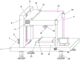
FIG. 1 is a perspective view of the structure of the present utility model;
FIG. 2 is a front view of the structure of the present utility model;
FIG. 3 is a cross-sectional view of the structure of the present utility model;
fig. 4 is a top view of the marking station of the present utility model.
In the figure: 1. an operation table; 2. a motor I; 3. a mounting groove; 4. a first belt pulley; 5. a second belt pulley; 6. a screw rod; 7. a first sliding block; 8. a fixed block; 9. a U-shaped groove; 10. a U-shaped block; 11. a motor II; 12. a bolt; 13. a mounting block; 14. a first chute; 15. a screw rod; 16. a fixed cylinder; 17. a limit slide bar; 18. a through groove; 19. a second slide block; 20. a connecting rod; 21. a laser emitter; 22. marking table; 23. a bidirectional screw rod; 24. square slide block; 25. a fixing plate; 26. a transverse calibration line; 27. a longitudinal calibration line; 28. a support column; 29. and a controller.
Detailed Description
The technical solutions of the embodiments of the present utility model will be clearly and completely described below in conjunction with the embodiments of the present utility model, and it is apparent that the described embodiments are only some embodiments of the present utility model, not all embodiments. All other embodiments, which can be made by one of ordinary skill in the art based on the embodiments of the utility model without making any inventive effort, are intended to be within the scope of the utility model.
Example 1
As shown in fig. 1 to 4, this embodiment provides a super laser marking machine with automatic positioning function, which comprises an operation table 1, a lifting mechanism, positioning mechanism and fixed establishment, the top of operation panel 1 is provided with elevating system, elevating system includes fixed block 8, the inside of operation panel 1 is provided with mounting groove 3, the top of mounting groove 3 just is located the top of operation panel 1 and is provided with motor No. 2, the output fixed connection of motor No. 2 is the belt pulley 4 and extends to the inside of mounting groove 3, the inside of fixed block 8 is provided with U type groove 9,U type groove 9's inside fixedly connected with lead screw 6, the outside sliding connection of lead screw 6 has slider 7 No. 7, the one end fixedly connected with No. two belt pulley 5 and extend to the inside of mounting groove 3, no. 4 and No. two belt pulley 5 pass through belt drive connection, the top of operation panel 1 just is located one side fixed connection spacing slide bar 17 of keeping away from fixed block 8, one side of No. 7 is provided with positioning mechanism.
In this embodiment, install motor 2 on the operation panel through mounting groove 3, then drive belt pulley 4 through motor 2 of start number, make No. two belt pulley 5 rotate, thereby drive lead screw 6 and rotate, cooperation fixed block 8 and U type groove 9 use, can make slider 7 remove, thereby drive positioning mechanism and remove, with adjusting positioning mechanism's height, the staff's operation of being convenient for, can make laser emitter automatic positioning need beat the position of mark, be favorable to improving automaticly and beat the mark precision, staff's intensity of labour has been reduced, high efficiency, excellent in use effect, the spacing slide bar 17 of cooperation setting simultaneously multiplicable lifting process's stability.
Example 2
As shown in fig. 1 to 4, based on the same concept as that of the above embodiment 1, this embodiment also provides a super laser marking machine with an automatic positioning function, the positioning mechanism includes a U-shaped block 10, one side fixedly connected with U-shaped block 10 of the first slider 7, an inside fixedly connected with installation block 13 of the U-shaped block 10, the inside of the U-shaped block 10 and be located between the inner wall of the U-shaped block 10 and the installation block 13, no. two motor 11 is provided with a second motor 11, the output end fixedly connected with lead screw 15 of the second motor 11, the outside of the lead screw 15 and be located inside sliding connection No. two sliders 19 of the installation block 13, the bottom fixedly connected with connecting rod 20 of the second slider 19, the bottom end fixedly connected with laser emitter 21 of the connecting rod 20, one side fixedly connected with fixed cylinder 16 of the installation block 13 is kept away from to the installation block 13, one end fixedly connected with slide bar of the second slider 19 is kept away from the connecting rod 20, no. 14 and through groove 18 are provided with respectively, the slide bar and No. 14 slide groove 14 are connected with first slide groove 14, and No. one slide groove 14 slide groove 10 slide, no. two motor 11 then drive No. two sliders 11 and then use the second slider 19 to drive the second slider to drive the laser emitter 19 and the automatic positioning device, thereby the automatic positioning device is used, and the automatic positioning device is driven by the second slider 19, and the automatic positioning device is driven by the second slider, and the automatic positioning device is driven by the slider and the slider, and the slider is driven by the slider and the slider.
The top of the operation table 1 and the lower side of the installation block 13 are provided with fixing mechanisms, the fixing mechanisms comprise marking tables 22, marking tables 22 are arranged at the tops of the operation table 1 and between the fixing blocks 8 and the limiting sliding rods 17, bidirectional screws 23 are arranged in the marking tables 22, square sliding blocks 24 are symmetrically and slidingly connected to the outsides of the bidirectional screws 23 and the insides of the marking tables 22, fixing plates 25 are fixedly connected to the tops of the two square sliding blocks 24, one ends of the fixing plates 25 extend to the upper side of the marking tables 22, objects to be marked are placed on the marking tables 22, and then the two square sliding blocks 24 are driven to move in opposite directions through rotating the bidirectional screws 23, so that the two fixing plates 25 are driven to move in opposite directions, the marked objects are fixed, the problem that the marked objects are not fixed due to the marked objects in the process is avoided, displacement is easy to occur when workers touch the marked objects, and the marking accuracy is easy to be reduced, and the practical application is facilitated.
Wherein, the both sides of U type piece 10 all threaded connection has bolt 12, and the inside that the one end of bolt 12 extends to installation piece 13 just runs through U type piece 10, through the bolt 12 that sets up can increase stability.
Wherein, support columns 28 are fixedly connected with four corners of the bottom of the operation table 1.
Wherein, the top of marking table 22 is crisscross to be provided with horizontal calibration line 26 and vertical calibration line 27, can improve the precision of automatic positioning through horizontal calibration line 26 and vertical calibration line 27 that set up, is favorable to practical application.
Wherein, the outside of operation panel 1 is provided with controller 29, no. one motor 2, no. two motors 11 and laser emitter 21 all with controller 29 electric connection, can start No. one motor 2, no. two motors 11 and laser emitter 21 through controller 29, easy operation is favorable to improving the practicality.
The working principle is that the device is moved to a required position, then a marking object is placed on the marking table 22, then two square sliding blocks 24 are driven to move in the opposite direction through rotating a bidirectional screw rod 23, so that two fixing plates 25 are driven to move in the opposite direction, the marking object is fixed, then a second motor 11 is fixed through a U-shaped block 10, then a first motor 11 is started through a controller 29 to drive a screw rod 15 to rotate, the mounting block 13 is matched for use, and accordingly the second sliding block 19 is driven to move, a slide bar slides in a first sliding groove 14, a laser emitter 21 is driven by a connecting rod 20 to slide in a first sliding groove 19, the laser emitter 21 is driven to slide in a through groove 18, the laser emitter 21 can be driven to automatically position through the driving of the connecting rod 20, the automatic positioning accuracy of the automatic positioning of the laser emitter 21 can be improved through the cooperation of a transverse calibration line 26 and a longitudinal calibration line 27, the automatic positioning accuracy of the automatic positioning can be improved, the automatic and the utilization ratio of human resources can be improved, when the focusing range of the laser emitter 21 needs to be adjusted, the first motor 2 is started through the controller 29, the first motor 2 is started to drive the first belt pulley 4 to rotate, the second belt pulley 5 is driven to rotate through the controller, the second belt pulley 6 is driven to rotate, the labor rod 6 is driven to rotate, the fixing block 8 and the U-shaped block 9 is matched to move, the first sliding block 9 can slide block 7 is driven to slide in the position 7, the laser emitter 21 can be driven to move in the position of the laser emitter 21, the automatic positioning accuracy of the laser emitter can be adjusted through the automatic calibration line can be adjusted, the laser emitter 21 can be adjusted to move the laser emitter 21, the accuracy can be adjusted and the accuracy of the laser emitter can be adjusted by the automatic positioning accuracy can be adjusted by the laser source can be adjusted to the accuracy can be adjusted by the accuracy and can be adjusted by the user can be well and high speed can be well by the user to change the accuracy and high speed can and high speed can be well.
The foregoing description of the preferred embodiments of the utility model is not intended to be limiting, but rather is intended to cover all modifications, equivalents, alternatives, and improvements that fall within the spirit and scope of the utility model.
Claims (7)
1. The utility model provides a super laser marking machine with automatic positioning function, includes operation panel (1), elevating system, positioning mechanism and fixed establishment, a serial communication port, the top of operation panel (1) is provided with elevating system, elevating system includes fixed block (8), the inside of operation panel (1) is provided with mounting groove (3), the top of mounting groove (3) and the top that is located operation panel (1) are provided with motor (2) No. one, the inside that output fixed connection of motor (2) No. one belt pulley (4) and extended to mounting groove (3), the inside of fixed block (8) is provided with U type groove (9), the inside fixedly connected with lead screw (6) of U type groove (9), the outside sliding connection of lead screw (6) has slider (7) No. one, the one end fixedly connected with No. two belt pulleys (5) and extend to the inside of mounting groove (3), no. one belt pulley (4) and No. two belt pulleys (5) are connected through belt drive, operation panel (1) and No. 8) are located one side of fixed connection slider (17) that fixed connection has.
2. The super laser marking machine with automatic positioning function according to claim 1, wherein the positioning mechanism comprises a U-shaped block (10), one side fixedly connected with U-shaped block (10) of a slider (7), inside fixedly connected with installation piece (13) of U-shaped block (10), inside and being located of U-shaped block (10) are provided with No. two motors (11) between inner wall and installation piece (13) of U-shaped block (10), the output fixedly connected with lead screw (15) of No. two motors (11), the outside of lead screw (15) just is located inside sliding connection No. two slider (19) of installation piece (13), the bottom fixedly connected with connecting rod (20) of No. two slider (19), bottom fixedly connected with laser emitter (21) of connecting rod (20), one side fixedly connected with fixed cylinder (16) of keeping away from U-shaped block (10) of installation piece (13), spacing slide bar (17) and fixed cylinder (16) sliding connection, no. two slider (19) keep away from inside and be provided with slider (14) and one side fixedly connected with slider (14), slider (14) and one side sliding groove (14) are connected with one side respectively.
3. The super laser marking machine with automatic positioning function according to claim 1, wherein a fixing mechanism is arranged at the top of the operation table (1) and below the installation block (13), the fixing mechanism comprises a marking table (22), the marking table (22) is arranged at the top of the operation table (1) and between the fixing block (8) and the limit sliding rod (17), a bidirectional screw (23) is arranged in the marking table (22), square sliding blocks (24) are symmetrically and slidingly connected at the outer sides of the bidirectional screw (23) and inside the marking table (22), fixing plates (25) are fixedly connected at the tops of the two square sliding blocks (24), and one ends of the fixing plates (25) extend to the upper side of the marking table (22).
4. The super laser marking machine with the automatic positioning function according to claim 2, wherein bolts (12) are connected to two sides of the U-shaped block (10) in a threaded mode, and one end of each bolt (12) extends to the inside of the corresponding mounting block (13) and penetrates through the U-shaped block (10).
5. The super laser marking machine with the automatic positioning function according to claim 1, wherein support columns (28) are fixedly connected to four corners of the bottom of the operation table (1).
6. A machine as claimed in claim 3, characterized in that the top of the marking table (22) is provided with transverse (26) and longitudinal (27) calibration lines in a staggered manner.
7. The super laser marking machine with the automatic positioning function according to claim 1, wherein a controller (29) is arranged on the outer side of the operating platform (1), and the first motor (2), the second motor (11) and the laser transmitter (21) are electrically connected with the controller (29).
Priority Applications (1)
| Application Number | Priority Date | Filing Date | Title |
|---|---|---|---|
| CN202223193137.2U CN219004942U (en) | 2022-11-30 | 2022-11-30 | Super laser marking machine with automatic positioning function |
Applications Claiming Priority (1)
| Application Number | Priority Date | Filing Date | Title |
|---|---|---|---|
| CN202223193137.2U CN219004942U (en) | 2022-11-30 | 2022-11-30 | Super laser marking machine with automatic positioning function |
Publications (1)
| Publication Number | Publication Date |
|---|---|
| CN219004942U true CN219004942U (en) | 2023-05-12 |
Family
ID=86236099
Family Applications (1)
| Application Number | Title | Priority Date | Filing Date |
|---|---|---|---|
| CN202223193137.2U Active CN219004942U (en) | 2022-11-30 | 2022-11-30 | Super laser marking machine with automatic positioning function |
Country Status (1)
| Country | Link |
|---|---|
| CN (1) | CN219004942U (en) |
-
2022
- 2022-11-30 CN CN202223193137.2U patent/CN219004942U/en active Active
Similar Documents
| Publication | Publication Date | Title |
|---|---|---|
| CN219004942U (en) | Super laser marking machine with automatic positioning function | |
| CN210361674U (en) | Double-side slotting device of woodworking edge banding machine | |
| CN216370716U (en) | Precise laser cutting machine for composite board | |
| CN207344762U (en) | A kind of plate quickly adjusts grooving apparatus | |
| CN203957542U (en) | The point position machine of many workbenches | |
| CN109732137A (en) | Cutting equipment is used in a kind of machine-building design | |
| CN211946110U (en) | Self-propelled crawler elevator | |
| CN113547835A (en) | Automatic lifting structure of printing platform | |
| CN208914281U (en) | A kind of side opening machine convenient for quickly positioning | |
| CN220463682U (en) | Web equipment frock | |
| CN220262467U (en) | Vertical multifunctional double-head engraving machine | |
| CN214352771U (en) | Injection molding machine leads to material tool for auto-parts | |
| CN215790429U (en) | Environment-friendly pet house timber precision finishing is with saw cutting equipment | |
| CN220144423U (en) | Pipe bending machine convenient to operate | |
| CN220196000U (en) | Bending machine with cutting function | |
| CN220782879U (en) | Semi-automatic screw locking machine | |
| CN220561535U (en) | Workpiece scribing device for machine manufacturing | |
| CN218966469U (en) | Code spraying device for backlight source | |
| CN215824110U (en) | Punching equipment for processing section doors and windows | |
| CN218852024U (en) | Proof press for tailoring | |
| CN220446432U (en) | Workbench with rotation function for producing engine | |
| CN219522385U (en) | Reference positioning device for wood board surface | |
| CN109531712A (en) | A kind of plate drilling equipment with arcuate guide mechanism | |
| CN220813655U (en) | Water baffle | |
| CN212948250U (en) | Plank cutting device is used in furniture production |
Legal Events
| Date | Code | Title | Description |
|---|---|---|---|
| GR01 | Patent grant | ||
| GR01 | Patent grant |