CN219004096U - Steel sheet processing calendering device - Google Patents
Steel sheet processing calendering device Download PDFInfo
- Publication number
- CN219004096U CN219004096U CN202223261884.5U CN202223261884U CN219004096U CN 219004096 U CN219004096 U CN 219004096U CN 202223261884 U CN202223261884 U CN 202223261884U CN 219004096 U CN219004096 U CN 219004096U
- Authority
- CN
- China
- Prior art keywords
- fixedly connected
- steel plate
- supporting seat
- groove block
- steel sheet
- Prior art date
- Legal status (The legal status is an assumption and is not a legal conclusion. Google has not performed a legal analysis and makes no representation as to the accuracy of the status listed.)
- Active
Links
Images


Classifications
-
- Y—GENERAL TAGGING OF NEW TECHNOLOGICAL DEVELOPMENTS; GENERAL TAGGING OF CROSS-SECTIONAL TECHNOLOGIES SPANNING OVER SEVERAL SECTIONS OF THE IPC; TECHNICAL SUBJECTS COVERED BY FORMER USPC CROSS-REFERENCE ART COLLECTIONS [XRACs] AND DIGESTS
- Y02—TECHNOLOGIES OR APPLICATIONS FOR MITIGATION OR ADAPTATION AGAINST CLIMATE CHANGE
- Y02P—CLIMATE CHANGE MITIGATION TECHNOLOGIES IN THE PRODUCTION OR PROCESSING OF GOODS
- Y02P70/00—Climate change mitigation technologies in the production process for final industrial or consumer products
- Y02P70/10—Greenhouse gas [GHG] capture, material saving, heat recovery or other energy efficient measures, e.g. motor control, characterised by manufacturing processes, e.g. for rolling metal or metal working
Landscapes
- Cleaning In General (AREA)
Abstract
The utility model discloses a steel plate processing calendaring device which comprises a supporting seat, wherein one end of the upper part of the supporting seat is fixedly connected with a groove block, the upper part of the inner part of the groove block is rotationally connected with a driving wheel, and the lower part of the inner part of the groove block is rotationally connected with an auxiliary wheel; the upper middle part fixedly connected with fixed curb plate of supporting seat, the spout has been seted up at the upper middle part of fixed curb plate, the inside sliding fit of spout has the slip pivot, the top fixedly connected with arc opening of slip pivot, arc open-ended top fixedly connected with grip block. Through above-mentioned structure, the steel sheet is pegged graft in the inside of fixed curb plate, and between slip pivot and the fixed pivot to through the rotation of hand wheel, make threaded rod and mount carry out screw-thread fit after rotating, reach the grip block and push down the operation to slip pivot, make its slip pivot atress push down, to steel sheet gravity centre gripping, realize pushing down and extending action, increase the action of gravity.
Description
Technical Field
The utility model relates to the technical field of steel plate processing, in particular to a steel plate processing calendaring device.
Background
The calender is a workpiece which is formed by arranging two or more rollers according to a certain form and pressing and extending a steel plate into a certain thickness and a certain surface shape at a certain temperature.
In the prior art, the rolling process is to extend the steel plate through the press roller to achieve rolling operation, the required thickness is not achieved when rolling, the required effect can be achieved through repeated rolling, the rolling roller is capable of rolling by self weight, the weight cannot be adjusted, the rolling speed is affected, meanwhile, the temperature of the steel plate is high, the operator is hot in the feeding process, and the operation is inconvenient.
Disclosure of Invention
The utility model aims to provide a steel plate processing calendaring device, which is characterized in that a threaded rod is in threaded fit with a fixing frame after a hand wheel rotates, so that a clamping plate can push down a sliding rotating shaft, the sliding rotating shaft is stressed to push down, the steel plate is clamped by gravity, the pushing down and extending effects are realized, and the gravity effect is increased. To achieve the above object, there is provided a steel sheet processing rolling apparatus comprising: the support seat is fixedly connected with a groove block at one end above the support seat, a driving wheel is rotationally connected above the inside of the groove block, and an auxiliary wheel is rotationally connected below the inside of the groove block;
the upper middle part of the supporting seat is fixedly connected with a fixed side plate, the upper middle part of the fixed side plate is provided with a sliding groove, the sliding shaft is in sliding fit with the sliding groove, an arc-shaped opening is fixedly connected above the sliding shaft, and a clamping plate is fixedly connected above the arc-shaped opening;
the other end of the upper part of the supporting seat is fixedly connected with a cleaning box.
According to a steel sheet processing calendering device, the bottom both sides of grip block all rotate and be connected with the bull stick, the bottom fixedly connected with threaded rod of bull stick, the bottom threaded connection of threaded rod has the mount, and mount and supporting seat fixed connection.
According to a steel sheet processing calendering device, the bottom fixedly connected with hand wheel of threaded rod, the middle part below of fixed curb plate rotates and is connected with fixed pivot, all fixedly connected with compression roller between fixed pivot and the slip pivot.
According to the steel plate processing calendaring device, the upper side and the lower side of the inside of the cleaning box are respectively and rotatably connected with a first brush roller and a second brush roller.
According to a steel sheet processing calendering device, the discharging pipe has been seted up at the bottom middle part of cleaning box, the bottom fixedly connected with discharge gate of discharging pipe.
According to the steel plate processing calendaring device, steel plates penetrate through the groove blocks, the fixed side plates and the cleaning box.
According to the steel plate processing calendaring device, one side of the groove block is fixedly connected with a plurality of first motors, and the driving ends of the first motors are fixedly connected with the driving wheels.
According to the steel plate processing calendaring device, a second motor is fixedly connected to the upper portion of the middle of the cleaning box, and the driving end of the second motor is fixedly connected with the second brush roller.
The beneficial effects are that:
1. compared with the prior art, the steel plate feeding device is provided with the groove blocks, the driving wheels and the auxiliary wheels, the steel plate is inserted into the groove blocks, and the first motor is driven between the driving wheels and the auxiliary wheels to drive the driving wheels to rotate so as to drive the steel plate to move, so that automatic feeding operation is realized, and the problem that the steel plate is high in temperature and inconvenient for workers in the prior art is solved.
2. Compared with the prior art, the steel plate pressing roller is provided with the fixed side plate, the sliding rotating shaft, the fixed rotating shaft and the threaded rod, the steel plate is inserted into the fixed side plate, the sliding rotating shaft and the fixed rotating shaft are in threaded fit through rotation of the hand wheel, the threaded rod and the fixing frame are in threaded fit after rotation, the clamping plate is used for pressing down the sliding rotating shaft to enable the sliding rotating shaft to be pressed down under the force of the clamping plate, the steel plate is clamped under the gravity, the pressing and extending effects are achieved, the gravity effect is increased, and the problem that the pressing roller in the prior art is limited in weight and needs repeated calendaring operations for many times is solved.
3. Compared with the prior art, the steel plate surface impurity cleaning device is provided with the second motor, the second brush roller and the discharging pipe, the second brush roller is driven by the second motor to rotate, the first brush roller and the second brush roller are matched in a rotating way after rotating, the surface impurity of the steel plate is cleaned, and the steel plate is circulated through the discharging pipe and discharged through the discharging hole after cleaning, so that unified treatment is achieved.
Additional aspects and advantages of the utility model will be set forth in part in the description which follows, and in part will be obvious from the description, or may be learned by practice of the utility model.
Drawings
The utility model is further described below with reference to the drawings and examples;
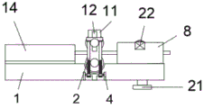
FIG. 1 is a cross-sectional side view of a rolling apparatus for working steel sheet according to the present utility model;
FIG. 2 is a perspective schematic structure diagram of a clamping plate and a fixing frame of the steel plate processing calendaring device;
FIG. 3 is a front view of a groove block of a steel plate processing and calendaring device according to the utility model;
fig. 4 is a side view of a drawing of a rolling apparatus for processing steel sheet according to the present utility model.
Legend description:
1. a support base; 2. a threaded rod; 3. fixing the rotating shaft; 4. a fixing frame; 5. a first brush roller; 6. a discharge pipe; 7. a steel plate; 8. a cleaning box; 9. a second brush roller; 10. a sliding rotating shaft; 11. fixing the side plates; 12. a chute; 13. a clamping plate; 14. a groove block; 15. an arc opening; 16. a rotating rod; 17. a hand wheel; 18. a driving wheel; 19. a first motor; 20. an auxiliary wheel; 21. a discharge port; 22. and a second motor.
Detailed Description
Reference will now be made in detail to the present embodiments of the present utility model, examples of which are illustrated in the accompanying drawings, wherein the accompanying drawings are used to supplement the description of the written description so that one can intuitively and intuitively understand each technical feature and overall technical scheme of the present utility model, but not to limit the scope of the present utility model.
Referring to fig. 1 to 4, a steel sheet working rolling apparatus according to an embodiment of the present utility model includes: the steel plate 7 is inserted into the groove block 14, the driving wheel 18 and the auxiliary wheel 20 are connected with the driving wheel 18 in a rotating mode, the driving wheel 18 is used for driving, the driving action is achieved, the auxiliary wheel 20 is connected with the lower portion of the inner portion of the groove block 14 in a rotating mode, the auxiliary wheel 20 is kept stable, rolling is assisted, the steel plate 7 penetrates through the groove block 14, the fixed side plate 11 and the cleaning box 8, a plurality of first motors 19 are fixedly connected to one side of the groove block 14, the driving wheel 18 is driven to rotate to drive the steel plate 7, the steel plate 7 is inserted into the fixed side plate 11 after moving, and the driving end of the first motors 19 is fixedly connected with the driving wheel 18;
the upper middle part of the supporting seat 1 is fixedly connected with a fixed side plate 11, both sides of the middle part of the top end of the supporting seat 1 are respectively provided with a fixed side plate 11, a chute 12 is formed in the upper middle part of the fixed side plate 11, position adjustment is realized through the chute 12, the sliding shaft 10 is slidingly matched with the inside of the chute 12, an arc opening 15 is fixedly connected to the upper part of the sliding shaft 10, a clamping plate 13 is fixedly connected to the upper part of the arc opening 15, the arc opening 15 is conveniently controlled in height position through the clamping plate 13, the two sides of the bottom end of the clamping plate 13 are respectively and rotatably connected with a rotating rod 16, the bottom end of the rotating rod 16 is fixedly connected with a threaded rod 2, the bottom end of the threaded rod 2 is in threaded connection with a fixing frame 4, the fixing frame 4 is fixedly connected with the supporting seat 1, a hand wheel 17 is fixedly connected with the bottom end of the threaded rod 2 through rotation of the hand wheel 17, the threaded rod 2 and the fixing frame 4 are in threaded fit after rotation, the hand wheel 17 is pressed down, the sliding shaft 10 is pressed down by the clamping plate 13, the gravity clamping of the steel plate 7 is realized, the pressing and the extending effect is realized, the lower part of the fixed side plate 11 is rotatably connected with a fixed rotating shaft 3, the threaded rod 2 and the pressing roller 10 is fixedly connected with the pressing roller 10 through the pressing roller;
the top other end fixedly connected with cleaning box 8 of supporting seat 1, the clearance of impurity is convenient for through cleaning box 8, solve the manual operation fatigue of staff, the inside upper and lower both sides of cleaning box 8 all rotate and are connected with first brush roller 5 and second brush roller 9, first brush roller 5 and second brush roller 9 all adopt steel wire material, discharging pipe 6 has been seted up at the bottom middle part of cleaning box 8, impurity circulates through discharging pipe 6 after the clearance, and discharge through discharge gate 21, reach unified processing, the bottom fixedly connected with discharge gate 21 of discharging pipe 6, the middle part top fixedly connected with second motor 22 of cleaning box 8, the inside of steel sheet 7 entering cleaning box 8, through the drive of second motor 22, make its second brush roller 9 rotate, rotate the back and carry out normal running fit through first brush roller 5 and second brush roller 9, the surface impurity clearance operation with steel sheet 7, and the drive end of second motor 22 and second brush roller 9 fixed connection.
Working principle: when the steel plate 7 is used, the steel plate 7 is inserted into the groove block 14, and is arranged between the driving wheel 18 and the auxiliary wheel 20, then the driving wheel 18 is driven by the first motor 19, the driving wheel 18 is rotated, the steel plate 7 is driven to move, the steel plate 7 is inserted into the fixed side plate 11 after moving, the sliding rotating shaft 10 and the fixed rotating shaft 3 are in threaded fit through the rotation of the hand wheel 17, the threaded rod 2 and the fixed frame 4 are in threaded fit after rotating, the clamping plate 13 is used for pressing down the sliding rotating shaft 10, the sliding rotating shaft 10 is pressed down, the steel plate 7 is clamped by gravity, the pressing and extending effects are achieved, the extended steel plate 7 enters the cleaning box 8, the second brush roller 9 is driven by the second motor 22, the second brush roller 9 is rotated, the first brush roller 5 and the second brush roller 9 are in rotary fit after rotating, the surface impurity cleaning operation of the steel plate 7 is carried out, the cleaning operation is carried out through the discharging pipe 6 after cleaning, and the cleaning operation is discharged through the discharging hole 21, and unified treatment is achieved.
The embodiments of the present utility model have been described in detail with reference to the accompanying drawings, but the present utility model is not limited to the above embodiments, and various changes can be made within the knowledge of one of ordinary skill in the art without departing from the spirit of the present utility model.
Claims (8)
1. A steel sheet processing calendering device, characterized by comprising: the device comprises a supporting seat (1), wherein one end of the upper part of the supporting seat (1) is fixedly connected with a groove block (14), a driving wheel (18) is rotationally connected above the inner part of the groove block (14), and an auxiliary wheel (20) is rotationally connected below the inner part of the groove block (14);
the upper middle part of the supporting seat (1) is fixedly connected with a fixed side plate (11), a chute (12) is formed in the upper middle part of the fixed side plate (11), a sliding rotating shaft (10) is slidably matched in the chute (12), an arc-shaped opening (15) is fixedly connected above the sliding rotating shaft (10), and a clamping plate (13) is fixedly connected above the arc-shaped opening (15);
the other end of the upper part of the supporting seat (1) is fixedly connected with a cleaning box (8).
2. The steel plate processing calendaring device according to claim 1, characterized in that two sides of the bottom end of the clamping plate (13) are respectively and rotatably connected with a rotating rod (16), the bottom end of the rotating rod (16) is fixedly connected with a threaded rod (2), the bottom end of the threaded rod (2) is in threaded connection with a fixing frame (4), and the fixing frame (4) is fixedly connected with a supporting seat (1).
3. The steel plate processing calendaring device according to claim 2, characterized in that a hand wheel (17) is fixedly connected to the bottom end of the threaded rod (2), a fixed rotating shaft (3) is rotatably connected to the lower portion of the middle of the fixed side plate (11), and press rolls are fixedly connected between the fixed rotating shaft (3) and the sliding rotating shaft (10).
4. The steel plate processing calendaring device according to claim 1, wherein the upper side and the lower side of the interior of the cleaning box (8) are respectively and rotatably connected with a first brush roller (5) and a second brush roller (9).
5. The steel plate processing calendaring device according to claim 1, characterized in that a discharging pipe (6) is arranged in the middle of the bottom end of the cleaning box (8), and a discharging hole (21) is fixedly connected to the bottom end of the discharging pipe (6).
6. A steel sheet working rolling apparatus according to claim 1, wherein the inside of the groove block (14), the fixed side plate (11) and the cleaning tank (8) are penetrated by the steel sheet (7).
7. A steel plate processing calendaring device according to claim 1, characterized in that one side of the groove block (14) is fixedly connected with a plurality of first motors (19), and the driving end of the first motor (19) is fixedly connected with the driving wheel (18).
8. The steel plate processing calendaring device according to claim 1, characterized in that a second motor (22) is fixedly connected to the upper middle portion of the cleaning box (8), and the driving end of the second motor (22) is fixedly connected to the second brush roller (9).
Priority Applications (1)
| Application Number | Priority Date | Filing Date | Title |
|---|---|---|---|
| CN202223261884.5U CN219004096U (en) | 2022-12-06 | 2022-12-06 | Steel sheet processing calendering device |
Applications Claiming Priority (1)
| Application Number | Priority Date | Filing Date | Title |
|---|---|---|---|
| CN202223261884.5U CN219004096U (en) | 2022-12-06 | 2022-12-06 | Steel sheet processing calendering device |
Publications (1)
| Publication Number | Publication Date |
|---|---|
| CN219004096U true CN219004096U (en) | 2023-05-12 |
Family
ID=86234692
Family Applications (1)
| Application Number | Title | Priority Date | Filing Date |
|---|---|---|---|
| CN202223261884.5U Active CN219004096U (en) | 2022-12-06 | 2022-12-06 | Steel sheet processing calendering device |
Country Status (1)
| Country | Link |
|---|---|
| CN (1) | CN219004096U (en) |
-
2022
- 2022-12-06 CN CN202223261884.5U patent/CN219004096U/en active Active
Similar Documents
| Publication | Publication Date | Title |
|---|---|---|
| CN110052510A (en) | A kind of steel plate leveling machine | |
| CN210550218U (en) | Automatic change panel grinding device | |
| CN217371617U (en) | Roller polishing device | |
| CN219004096U (en) | Steel sheet processing calendering device | |
| CN112658904A (en) | Grinding device is used in mould production | |
| CN217832143U (en) | Device for simplifying processing of subway segment grabbing and lifting head | |
| CN207343773U (en) | A kind of new solid wheel shake-out equipment | |
| CN215393438U (en) | Automobile welding jig hold-down mechanism | |
| CN212351376U (en) | Marble panel grinding device for building | |
| CN210880888U (en) | Improved embossing roller | |
| CN208375003U (en) | A kind of polishing machine | |
| CN219094286U (en) | Frame double-end nut mills flat machine | |
| CN214287869U (en) | Iron powder automatic mixing machine for gear machining | |
| CN216513995U (en) | Take loading attachment's thread rolling wheel vacuum heat treatment device | |
| CN220637253U (en) | Burr removing device for plate processing | |
| CN219733351U (en) | Convenient controllable oil extraction device | |
| CN212075872U (en) | Fixing device is collected to cold-rolled steel sheet | |
| CN218255528U (en) | Automatic cutter adjusting cone of aluminum foil paper cutting machine | |
| CN212289259U (en) | Intelligence official working voucher leveling device | |
| CN219925414U (en) | Discharging device for centerless grinder | |
| CN209939783U (en) | Hydraulic plate turnover machine | |
| CN112061842B (en) | Cloth unloading traction frame | |
| CN215092503U (en) | A polisher for roll processing | |
| CN221020570U (en) | Shot blasting equipment for automobile supercharger production | |
| CN220863623U (en) | Surface treatment device for bag cage processing |
Legal Events
| Date | Code | Title | Description |
|---|---|---|---|
| GR01 | Patent grant | ||
| GR01 | Patent grant |