CN218997143U - New forms of energy quick charge connector and jump ring terminal - Google Patents
New forms of energy quick charge connector and jump ring terminal Download PDFInfo
- Publication number
- CN218997143U CN218997143U CN202320165887.4U CN202320165887U CN218997143U CN 218997143 U CN218997143 U CN 218997143U CN 202320165887 U CN202320165887 U CN 202320165887U CN 218997143 U CN218997143 U CN 218997143U
- Authority
- CN
- China
- Prior art keywords
- elastic
- terminal
- outer sleeve
- plug
- offset section
- Prior art date
- Legal status (The legal status is an assumption and is not a legal conclusion. Google has not performed a legal analysis and makes no representation as to the accuracy of the status listed.)
- Active
Links
Images


Abstract
The utility model discloses a new energy quick-charging connector and a clamp spring terminal, which comprise a terminal body and an outer sleeve sleeved on the outer side of the terminal body, wherein the front end of the terminal body is concavely provided with an elastic plug-in part for connecting a male terminal, and the elastic plug-in part can be stressed to expand outwards and lose force to return inwards; the outer sleeve is provided with a backstop part which extends outwards and backwards; through the elastic fit of elastic plug portion and elasticity butt portion, can stabilize the centre gripping male terminal and can restrict the expansion scope of elastic plug portion to improve the centre gripping stability between female terminal and the male terminal, simultaneously, prevent through the stopping portion that jump ring terminal from coming off from the casing, further increased connection stability, and simple structure.
Description
Technical Field
The utility model relates to the technical field of electrical element connectors, in particular to a new energy quick-charging connector and a clamp spring terminal.
Background
With the improvement of the popularity of new energy automobiles, the electric connector is used as a tie for connecting an external power supply and a rechargeable battery, plays a key role in influencing the performance of the whole automobile, and the requirements on the connection performance of the electric connector are increased increasingly due to the improvement of the performance requirements of the whole automobile and the expansion of the use environment.
The electrical connector generally comprises a snap spring terminal and a contact pin (arranged on a male terminal) which are in plug fit, wherein the snap spring terminal is provided with a plug port for plugging the contact pin, the conventional snap spring terminal is generally formed into an opening annular structure by bending a single-layer metal sheet to form the plug port to be matched with the contact pin on the male terminal, and the metal sheet is easy to cause fatigue failure due to frequent plug of the male terminal, so that the contact pin is very easy to fall off from the plug port, and the conduction of current between the contact pin and the snap spring terminal is influenced. In addition, the existing clamp spring terminal is generally provided with a clamping buckle structure on the outer wall to be matched with the shell of the electric connector to fix the clamp spring terminal, but the additionally-arranged clamping buckle structure is easy to abrade or age in the frequent inserting and pulling process of the contact pin, so that the whole clamp spring terminal is very easy to pull out in a lump when the contact pin is pulled out, the inserting and pulling of the contact pin and the clamp spring terminal are not facilitated, meanwhile, the additionally-arranged clamping buckle structure can also increase the production cost and the assembling procedure of the clamp spring terminal, and the machining efficiency is low.
Because the current output by the cable is larger in the power transmission process of the new energy automobile, the requirement on the connection reliability between the clamp spring terminal and the contact pin is higher, and therefore, a low-cost electric connector which can be processed efficiently and has high connection reliability is needed to be provided.
Disclosure of Invention
In view of the above, the present utility model aims to provide a new energy quick-charging connector and a snap spring terminal, so as to solve the problems of low connection reliability, easy falling off, high cost and complicated process of the electrical connector in the prior art.
In order to solve the technical problems, the technical scheme of the utility model provides a clamp spring terminal, which comprises a terminal body and an outer sleeve sleeved on the outer side of the terminal body, wherein the front end of the terminal body is concavely provided with an elastic plug-in part for connecting a male terminal, and the elastic plug-in part can be forced to expand outwards and lose force to return inwards; the outer sleeve is provided with a backstop part which extends outwards and backwards and an elastic supporting part which corresponds to the front side of the backstop part and is in elastic contact with the elastic plug-in part.
Further, the elastic plug-in connection part comprises a fixed ring for fixing the outer sleeve and a plurality of elastic plug-in connection pieces which are arranged at intervals along the circumferential direction of the fixed ring, the rear ends of the elastic plug-in connection pieces are connected to the fixed ring, and the front ends of the elastic plug-in connection pieces extend in the direction away from the fixed ring; the front end of the elastic insertion piece is concavely provided with a concave arc part which is elastically contacted with the elastic supporting part.
Further, the elastic plug-in piece comprises a first plug-in offset section and a second plug-in offset section which are integrally formed, one end of the first plug-in offset section is connected with the fixed ring, the other end of the first plug-in offset section is gradually close to the axis direction of the terminal body from the connection part of the first plug-in offset section and is connected with the second plug-in offset section, and one end of the second plug-in offset section, which is far away from the first plug-in offset section, is gradually far away from the axis direction of the terminal body from the connection part of the first plug-in offset section to form the concave arc part.
Further, a plurality of groove bodies are formed on the outer sleeve at intervals along the circumferential direction of the outer sleeve;
the retaining portions comprise retaining wings which are arranged in the groove body in one-to-one correspondence, the front ends of the retaining wings are connected with the side walls of the corresponding positions of the groove body, and the rear ends of the retaining wings gradually extend outwards and backwards away from the axis direction of the outer sleeve from the connection position of the retaining wings and the groove body.
Further, the elastic supporting part is concavely formed on the outer sleeve at the front side corresponding to the retaining part, and a plurality of giving-up grooves are formed on the outer sleeve at intervals at the position corresponding to the elastic inserting part;
the elastic supporting part comprises elastic supporting pieces which are formed in the yielding grooves in a one-to-one correspondence manner, the rear ends of the elastic supporting pieces are connected with the side walls of the corresponding sides of the yielding grooves, and the front ends of the elastic supporting pieces extend in the direction away from the connecting positions of the outer sleeves; the front end of the elastic supporting piece is inwards deflected to form a supporting part which is elastically contacted with the concave arc part.
Further, the elastic supporting piece comprises a horizontal section and a supporting offset section which are integrally formed, one end of the horizontal section is connected with the side wall of the yielding groove, the other end of the horizontal section is connected with the supporting offset section, and one end of the supporting offset section, which is far away from the horizontal section, gradually deviates from the joint of the supporting offset section and the horizontal section to the axial direction close to the outer sleeve.
Further, the front end of the outer sleeve is provided with a plurality of bending parts which are bent towards the inside of the outer sleeve and are distributed at intervals along the circumferential direction of the outer sleeve, and the front end of the elastic inserting piece is positioned in the accommodating space formed by bending of the bending parts.
Further, at least one mounting groove is formed on the fixing ring, and a clamping part which is matched with the mounting groove to fix the outer sleeve is formed on the outer sleeve at a position corresponding to the mounting groove;
the mounting groove is provided with a first groove wall and a second groove wall which are oppositely arranged, the central line extension line of the first groove wall is intersected with the central line extension line of the second groove wall, the clamping part comprises a first clamping block and a second clamping block which are correspondingly arranged on the outer sleeve and extend towards the axial direction of the outer sleeve, and the first clamping block and the second clamping block inwards extend into the mounting groove and correspondingly are clamped and abutted on the first groove wall and the second groove wall.
Further, a cable connection part for connecting the cables is formed at the rear end of the terminal body; the cable connecting part comprises a cable coating part which is integrally formed with the elastic plug part and is sequentially connected to the rear end of the elastic plug part and is used for coating a cable, and a cable fixing part which is used for fixing the cable;
the terminal body and the outer sleeve are both made of metal materials through stamping, and the hardness of the metal materials for making the outer sleeve is higher than that of the metal materials for making the terminal body.
In order to solve the technical problem, another technical scheme of the utility model provides a new energy quick-charging connector, which comprises a snap spring terminal and a male terminal which are in plug-in fit and a shell sleeved outside the snap spring terminal, wherein the snap spring terminal is the snap spring terminal, the male terminal is detachably plugged in the snap spring terminal and is in elastic contact with an elastic plug-in part of the snap spring terminal, the shell is sleeved outside the snap spring terminal, and the retaining part is buckled on the inner wall of the shell.
According to the utility model, the elastic plug-in part formed by surrounding the plurality of elastic plug-in pieces with the concave structures is arranged on the terminal body, when the male terminal of the connector is plugged in, the outer side wall of the elastic plug-in part can be elastically contacted with the concave arc parts on the elastic plug-in pieces and is extruded outwards, and the elastic pieces reversely press the male terminal under the elastic action of the elastic pieces, so that the electrical connection between the male terminal and the snap spring terminal of the connector is realized; in addition, the elastic supporting piece which is provided with the second concave arc part and is matched with the elastic inserting piece is arranged on the outer sleeve, so that the elasticity of the elastic inserting piece can be increased when the male terminal extrudes the elastic inserting piece outwards, and the connection reliability between the male terminal and the clamp spring terminal is ensured; meanwhile, the second concave arc part of the elastic supporting piece and the concave arc part of the elastic inserting piece have a certain gap in a natural state, so that when the elastic inserting piece expands outwards to a certain extent, the elastic contact between the elastic supporting piece and the second concave arc part can be realized, and the problem that the male terminal is difficult to insert and extract due to overlarge elastic force is avoided.
Drawings
Fig. 1 is a schematic structural view of embodiment 1 of a snap spring terminal of the present utility model.
Fig. 2 is a cross-sectional view of the snap spring terminal of fig. 1.
Fig. 3 is a schematic structural view of the terminal body in fig. 1.
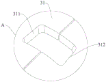
Fig. 4 is an enlarged structural view at a in fig. 3.
Fig. 5 is a schematic view of the outer sleeve of fig. 1.
Fig. 6 is a schematic structural diagram of a terminal body according to embodiment 2 of the present utility model.
Fig. 7 is a schematic view of the structure of the outer sleeve of embodiment 2 of the present utility model.
Fig. 8 is a schematic structural view of a snap spring terminal in embodiment 3 of the present utility model.
Fig. 9 is a schematic structural view of the terminal body in fig. 8.
Fig. 10 is a schematic view of the structure of the outer sleeve in fig. 8.
The specification reference numerals are as follows:
the terminal body 1, the first clearance gap 1a, the outer sleeve 2, the relief groove 2a, the groove body 2b, the retaining portion 21, the retaining wing 211, the positioning protrusion 22, the elastic insertion portion 3, the fixing ring 31, the mounting portion 31a, the positioning hole 31b, the first groove wall 311, the second groove wall 312, the third groove wall 313, the fourth groove wall 314, the elastic insertion piece 32, the concave arc portion 32a, the second clearance gap 32b, the first insertion offset section 321, the second insertion offset section 322, the cable connecting portion 4, the cable coating portion 41, the first arc connecting piece 411, the first cable clamping plate 412, the cable fixing portion 42, the second arc connecting piece 421, the second cable clamping plate 422, the elastic abutting portion 5, the elastic abutting piece 51, the abutting portion 51a, the horizontal portion 511, the abutting offset section 512, the bending portion 6, the accommodating space 6a, the clamping portion 7, the first clamping block 71, the second clamping block 72, the third clamping block 73, and the fourth clamping block 74.
Detailed Description
The following is a further detailed description of the embodiments:
example 1
As shown in fig. 1 and 2, the snap spring terminal of the present embodiment includes a terminal body 1 and an outer sleeve 2 sleeved outside the terminal body 1. The front end of the terminal body 1 is provided with an elastic plug-in part 3 which is concave and is used for connecting a male terminal (not shown), and the rear end of the terminal body 1 is provided with a cable connecting part 4 which is used for connecting a cable, so that when the male terminal is plugged into the elastic plug-in part 3, large current transmission between the male terminal and a clamp spring terminal can be realized; in this embodiment, the front end refers to an end of the clip spring terminal corresponding to the connection with the male terminal, and the rear end refers to an end of the clip spring terminal corresponding to the connection with the cable. The outer sleeve 2 is formed with an outward and backward extending stop portion 21, and the stop portion 21 can be buckled on a stop structure sleeved on the inner wall of an electric connector shell (not shown) outside the clamp spring terminal, so as to play a role in stopping the clamp spring terminal from falling off from the electric connector shell. An elastic supporting portion 5 which is concave and can be elastically contacted with the elastic plug-in portion 3 is formed on the outer sleeve 2 corresponding to the front side of the retaining portion 21 (i.e. the side corresponding to the front end close to the snap spring terminal), so as to increase the clamping force on the male terminal and limit the opening range of the elastic plug-in portion 3. In this embodiment, the terminal body 1 and the outer sleeve 2 are preferably cylindrical, and the elastic insertion portion 3 and the elastic abutting portion 5 are preferably annular structures coaxially disposed with the terminal body 1 or the outer sleeve 2; it can be appreciated that in other embodiments, the terminal body 1 and the outer sleeve 2 may have structures such as rectangular and oval according to the usage scenario of the electrical connector, and the shapes of the corresponding elastic inserting portion 3 and the elastic supporting portion 5 are adaptively adjusted along with the terminal body 1 and the outer sleeve 2 to have a ring-shaped structure surrounding the terminal body 1 and the outer sleeve 2 with rectangular or oval structures.
In this embodiment, the terminal body 1 and the outer sleeve 2 are both made of metal materials by punching, and the hardness of the metal material of which the outer sleeve 2 is made is greater than that of the metal material of which the terminal body 1 is made. Specifically, the terminal body 1 is preferably stamped from a copper alloy material with conductive properties, so as to form the elastic plug part 3 at the front end of the terminal body 1; the outer sleeve 2 is preferably punched from stainless steel materials, so that an elastic supporting part 5 is punched at the position of the front end of the outer sleeve 2 corresponding to the elastic plug-in part 3; and the hardness of the elastic plug-in part 3 is smaller than that of the elastic supporting part 5, so that when the elastic plug-in part 3 is expanded outwards to contact with the elastic supporting part 5, the elastic force of the elastic supporting part 5 can be overlapped to act on the male terminal together, and the clamping of the male terminal is more stable. It will be appreciated that the material of the terminal body 1 is not limited to copper alloy material, but may be other metal materials with conductive properties, and the material of the outer sleeve 2 is not limited to stainless steel material, but may be made of other materials with hardness higher than that of the terminal body 1.
Because the terminal body 1 and the outer sleeve 2 are made of metal materials, the elastic plug-in part 3 and the elastic supporting part 5 which are formed by stamping can elastically deform, namely, the elastic plug-in part 3 and the elastic supporting part 5 can be outwards opened under the action of external force and can be inwards returned automatically after the external force disappears, so that the connection and disconnection of the snap spring terminal and the male terminal are realized; when the male terminal is inserted into the elastic plug-in part 3, the outer wall of the male terminal is contacted with the inner wall of the concave elastic plug-in part 3 and the elastic plug-in part 3 is extruded outwards to enable the elastic plug-in part 3 to be outwards opened, when the elastic plug-in part 3 is opened to a certain extent, the outer wall of the elastic plug-in part 3 can be continuously contacted with the inner wall of the elastic supporting part 5 and further extruded outwards to enable the elastic supporting part 5 to be outwards opened synchronously, so that the elastic plug-in part 3 and the elastic supporting part 5 are overlapped to jointly realize clamping of the male terminal, stable clamping of the male terminal is ensured, and stable electric connection between the male terminal and the clamp spring terminal is realized; meanwhile, the elastic plug-in part 3 and the elastic propping part 5 are in a non-contact state in a natural state, and a first clearance gap 1a is formed between the elastic plug-in part 3 and the elastic propping part 5, so that the elastic plug-in part 3 and the elastic propping part 5 can jointly act on the clamping of the male terminal after being opened to a certain extent, the phenomenon that the clamping of the male terminal is not firm due to insufficient elasticity of the elastic plug-in part 3 with a single layer can be avoided, the opening range of the elastic plug-in part 3 can be limited, the fatigue yielding and the elastic failure of the elastic plug-in part 3 due to overlarge opening of the elastic plug-in part can be avoided, and the male terminal is not easy to insert due to overlarge elasticity caused by the fact that the elastic plug-in part 3 and the elastic propping part 5 are overlapped at first, so that the stability of the clamping of the male terminal is improved, and the plug-in of the male terminal is convenient.
As shown in fig. 3 and 4, the elastic plug-in portion 3 includes a fixing ring 31 and a plurality of elastic plug-in pieces 32 spaced along the circumferential direction of the fixing ring 31, the fixing ring 31 is used for positioning and fixing the outer sleeve 2, the elastic plug-in pieces 32 are integrally formed at the front end of the fixing ring 31, and the rear end of the fixing ring 31 is connected with the cable connecting portion 4; the elastic insertion piece 32 can elastically contact with the male terminal to clamp the male terminal.
The fixing ring 31 is formed with at least one mounting groove 31a, and the mounting groove 31a is used for being engaged with a corresponding position of the outer sleeve 2 in a clamping manner so as to fixedly sleeve the outer sleeve 2 outside the terminal body 1. Specifically, the mounting groove 31a has a first groove wall 311 and a second groove wall 312 that are disposed opposite to each other, and an extension line of a center line of the first groove wall 311 intersects with an extension line of a center line of the second groove wall 312 at a point, so that the mounting groove 31a is substantially in a trapezoid structure, and after the outer sleeve 2 is fixed, the trapezoid structure can fix the outer sleeve 2 from the axial direction, the radial direction and the circumferential direction of the terminal body 1 at the same time, so as to avoid relative movement between the terminal body 1 and the outer sleeve 2. In this embodiment, two mounting grooves 31a are provided on the fixed ring 31, and the two mounting grooves 31a are respectively arranged at the top and bottom of the fixed ring 31 in a relative manner to realize stable fixation of the outer sleeve 2, and meanwhile, the mounting grooves 31a are formed by adopting a stamping process, so that the production process and structure of the fixed ring 31 can be simplified; it will be appreciated that in other embodiments, the number of the mounting grooves 31a is not limited to two, but may be one, three, or other numbers, and when more than one mounting groove 31a is provided, the mounting grooves 31a may be uniformly spaced along the circumferential direction of the fixing ring 31 or may be non-equidistant, and meanwhile, the size of each mounting groove 31a may be the same or different, which only needs to satisfy that the extension lines of the central lines of the first groove wall 311 and the second groove wall 312 may intersect at one point.
The rear end of the elastic insertion piece 32 is connected to the fixed ring 31, the front end of the elastic insertion piece 32 is a free end and extends towards a direction away from the fixed ring 31, a concave arc portion 32a capable of elastically contacting with the male terminal and the elastic supporting portion 5 is formed at the free end (i.e. the front end) of the elastic insertion piece 32 in an inward concave manner, and when the male terminal is inserted, the male terminal is contacted with the inward concave portion of the concave arc portion 32a, so as to realize electrical connection between the male terminal and the snap spring terminal. In the present embodiment, a second clearance gap 32b is formed between two adjacent elastic inserting pieces 32 to form elastic inserting portions 3 where the elastic inserting pieces 32 and the second clearance gap 32b are spaced apart from each other, so as to avoid interference of each elastic inserting piece 32 when opening, and ensure that each elastic inserting piece 32 can be opened smoothly and outwards.
The elastic plug piece 32 comprises a first plug offset section 321 and a second plug offset section 322 which are integrally formed, and the first plug offset section 321 and the second plug offset section 322 are offset towards the axis direction of the terminal body 1 at one end connected with the first plug offset section 321 and the second plug offset section 322 so as to form a concave arc part 32a which is recessed towards the inside of the terminal body 1. Specifically, one end of the first plugging offset section 321 is connected to the fixed ring 31, the other end is offset (i.e., inwardly offset) from the connection with the fixed ring 31 toward the axis direction close to the terminal body 1 and is connected to the second plugging offset section 322, and one end of the second plugging offset section 322 away from the first plugging offset section 321 is offset (i.e., outwardly offset) from the connection with the first plugging offset section 321 toward the axis direction away from the terminal body 1 so as to be concave into a concave arc portion 32a having a substantially V-shaped structure at the connection of the first plugging offset section 321 and the second plugging offset section 322.
As shown in fig. 5, the retaining portion 21 includes at least one retaining wing 211 provided on the outer wall of the outer sleeve 2 for retaining the snap spring terminal. In the embodiment, three retaining wings 211 are arranged, the three retaining wings 211 are wound into a circle on the side surface of the outer sleeve 2 and can be clamped and fixed with three positions of a stop structure on the inner wall of the electric connector shell, so that the connection between the clamp spring terminal and the electric connector shell is more stable, and the whole clamp spring terminal is prevented from being carried out from the electric connector shell in the plugging process of the male terminal; it is understood that the number of the retaining wings 211 is not limited to three, and that a suitable number of retaining wings 211 may be provided according to the size of the snap spring terminal and the binding force between the snap spring terminal and the male terminal, so as to ensure stable connection between the snap spring terminal and the electrical connector housing. Specifically, the outer sleeve 2 is formed with grooves 2b disposed at intervals along the circumferential direction of the outer sleeve 2, the retaining wings 211 are disposed in the grooves 2b in a one-to-one correspondence, the front ends of the retaining wings 211 are connected with the side walls of the corresponding positions of the grooves 2b, and the rear ends of the retaining wings extend outwards and backwards from the connection position with the grooves 2b gradually away from the axial direction of the outer sleeve 2 so as to form retaining wings 211 inclined outwards backwards; in this embodiment, the retaining wing 211 is formed by integrally stamping with the outer sleeve 2, which simplifies the additionally arranged fastening structure, and the retaining wing 211 and the outer sleeve 2 are integrally formed, so that the connection is more stable compared with the additionally assembled fastening structure.
The outer sleeve 2 is provided with a plurality of grooves 2a arranged along the circumferential direction of the outer sleeve 2 at intervals at positions corresponding to the elastic plug-in connection parts 3, the elastic propping parts 5 comprise elastic propping pieces 51 which are formed in the grooves 2a in a one-to-one correspondence manner, and the grooves 2a can be used for stepping down the elastic propping pieces 51 when the elastic propping pieces 51 are outwards opened or inwards returned, so that the elastic propping pieces 51 can be smoothly opened or returned. The first clearance gap 1a is formed between the elastic supporting piece 51 and the elastic inserting piece 32, so that on one hand, the elastic force of the elastic inserting piece 32 can be consolidated, and on the other hand, the opening range of the elastic inserting piece 32 can be limited, thereby ensuring the contact stability of the elastic inserting piece 32 and the male terminal. In this embodiment, the number of the elastic supporting pieces 51 does not have to be in one-to-one correspondence with the number of the elastic inserting pieces 32, and may be more than, equal to or less than the number of the elastic inserting pieces 32, as long as it is satisfied that the elastic inserting pieces 32 are disposed along the axial direction of the outer sleeve and that when the elastic inserting pieces 32 are outwardly expanded, at least part of the outer wall of the elastic inserting piece 32 can be in elastic contact with the inner wall of the elastic supporting piece 51.
The rear end of the elastic supporting piece 51 is connected to the corresponding position of the outer sleeve 2, the front end of the elastic supporting piece 51 is a free end and extends in a direction away from the connection position of the elastic supporting piece with the outer sleeve 2, a supporting portion 51a capable of elastically contacting with the concave arc portion 32a on the elastic inserting piece 32 is formed at the free end (i.e. the front end) of the elastic supporting piece 51 in an inward deflection manner, and the end of the supporting portion 51a faces towards the concave position of the concave arc portion 32a and can elastically contact with the concave position. When the male terminal presses the elastic insertion piece 32 outward so that the elastic insertion piece 32 expands outward to a certain extent, the end of the abutting portion 51a contacts with the concave portion of the concave arc portion 32a to overlap the elastic force of the elastic abutting piece 51 and limit the expansion range of the elastic insertion piece 32, and the elastic insertion piece 32 is prevented from being expanded too much to cause fatigue yielding while stably clamping the male terminal.
The elastic supporting piece 51 comprises a horizontal section 511 and a supporting offset section 512 which are integrally formed. Specifically, the rear end of the horizontal segment 511 is connected to the outer sleeve 2, the front end extends horizontally along the axial direction of the outer sleeve 2 and is connected to the rear end of the abutting offset segment 512, and the front end of the abutting offset segment 512 is offset (i.e., offset outwards) from the connection with the horizontal segment 511 in a direction away from the axial direction of the outer sleeve 2, so as to form an abutting portion 51a inclined forward and inwards in a matching manner.
The front end of the outer sleeve 2 (specifically, the end corresponding to the front side of the elastic supporting portion 5) is formed with a plurality of bending portions 6 bending toward the inside of the outer sleeve 2, and the bending portions 6 are distributed at intervals along the circumferential direction of the outer sleeve 2, so that a containing space 6a opening toward the elastic inserting piece 32 can be formed at the end of the outer sleeve 2, and after the outer sleeve 2 is installed, the front end of the elastic inserting piece 32 can extend into the containing space 6a formed by bending of the bending portions 6, so that the end of the elastic inserting piece 32 is protected.
The outer sleeve 2 is also provided with a clamping part 7 which is matched with the mounting groove 31a and used for fixing the outer sleeve 2 at the position corresponding to the mounting groove 31 a; during installation, the clamping part 7 can extend into the mounting groove 31a and be clamped and combined with the mounting groove 31a to fix the outer sleeve 2 on the terminal body 1, and meanwhile, the clamping part 7 and the mounting groove 31a can also play a role in positioning the outer sleeve 2 due to the fact that the clamping part 7 and the mounting groove 31a are arranged in an adapting mode. Specifically, the clamping portion 7 includes a first clamping block 71 and a second clamping block 72 that are disposed on the outer sleeve 2 corresponding to the first groove wall 311 and the second groove wall 312 and extend toward the axial direction of the outer sleeve 2, and similarly, an extension line of a center line of the first clamping block 71 and an extension line of a center line of the second clamping block 72 intersect at a point, and the extension lines of the center line of the first clamping block 71 and the center line of the second clamping block 72 are parallel to the extension lines of the center lines of the first groove wall 311 and the second groove wall 312 on the corresponding sides, respectively, so that when the first clamping block 71 and the second clamping block 72 extend inward into the mounting groove 31a, the first clamping block 71 and the second clamping block 72 can be clamped and abutted on the first groove wall 311 and the second groove wall 312 on the corresponding sides, thereby realizing the fixation of the outer sleeve 2 and the terminal body 1 and avoiding the outer sleeve 2 from falling off from the terminal body 1.
The cable connecting portion 4 includes a cable coating portion 41 and a cable fixing portion 42 integrally formed with the elastic plug portion 3 and sequentially connected to the rear end of the elastic plug portion 3, the cable coating portion 41 is used for coating a cable, and the cable fixing portion 42 is used for fixing the cable, so that the cable is prevented from entering the elastic plug portion 3 forward and from falling out of the cable coating portion 41 backward. In this embodiment, the cable coating portion 41 includes a first arc-shaped connecting piece 411 connected to the rear end of the elastic plugging portion 3 (specifically, the fixing ring 31), and a first cable clamping plate 412 formed on two opposite sides of the first arc-shaped connecting piece 411 and extending outwards, where the first arc-shaped connecting piece 411 is used for placing a cable, the first arc-shaped connecting piece 411 preferably adopts a semicircular structure coaxially arranged with the fixing ring 31, and the first cable clamping plates 412 are formed on two straight sides of the semicircular structure and extending outwards in a direction away from the first arc-shaped connecting piece 412, so as to coat the cable from two sides, thereby realizing coating of the cable; the cable fixing portion 42 includes a second arc connecting piece 421 connected to the rear end of the first arc connecting piece 411, and a second cable clamping plate 422 formed on two opposite sides of the second arc connecting piece 421 and extending outwards, where the second arc connecting piece 421 is used for placing a cable, and similarly, the second arc connecting piece 421 preferably adopts a semicircular structure coaxially arranged with the fixing ring 31, and the second cable clamping plates 422 are formed on straight sides of two opposite sides of the semicircular structure and extend outwards in a direction away from the second arc connecting piece 422, so as to be capable of bending inwards from two sides to fix the cable.
The new energy quick-charge connector provided by the other embodiment of the utility model comprises a snap spring terminal and a male terminal which are in plug-in fit and a shell sleeved outside the snap spring terminal, wherein the snap spring terminal is the snap spring terminal, and the male terminal is detachably plugged in the snap spring terminal and is in elastic contact with an elastic plug-in part 3 of the snap spring terminal; the shell is sleeved outside the clamp spring terminal, and the retaining part 21 is buckled on the inner wall of the shell. Of course, the electrical connector further includes structures such as a terminal block and a cable except for the snap spring terminal, the male terminal and the housing, and the terminal block and the cable structure can be implemented by adopting existing structures, which are not described herein.
According to the clamp spring terminal, the elastic inserting piece 32 and the elastic supporting piece 51 which can be in elastic contact are arranged, the elastic supporting piece 51 can be overlapped and act on the male terminal through the outward expansion of the stress of the elastic inserting piece 32, so that the male terminal is more stable to connect, the male terminal is prevented from falling off, meanwhile, the elastic supporting piece 51 can also limit the expansion range of the elastic inserting piece 32, fatigue failure caused by overlarge expansion of the elastic inserting piece 32 is avoided, the service life of the elastic inserting piece 32 can be effectively prolonged, and the connection stability of the male terminal is improved; and through setting up the stopping portion 21, make jump ring terminal can stable connection on the casing of electric connector, avoid the jump ring terminal to be taken out along with the pull out of public terminal to further improve connection stability, simple structure, convenient operation has stronger practicality.
Example 2
Fig. 6 and 7 are schematic structural views of the clip spring terminal according to the present embodiment. The clip spring terminal of this embodiment includes a terminal body 1 and an outer sleeve 2 which are identical or similar in structure and function to those of the clip spring terminal of embodiment 1. The difference in this embodiment is that:
the mounting groove 31a of the present embodiment has a third groove wall 313 and a fourth groove wall 314 that are disposed opposite to each other, and the third groove wall 313 and the fourth groove wall 314 are parallel to each other, so that the mounting groove 31a has a substantially rectangular structure, and when the outer sleeve 2 is fixed, the rectangular structure can fix the outer sleeve 2 from the axial direction, the radial direction and the circumferential direction of the terminal body 1 at the same time, so as to avoid the relative movement between the terminal body 1 and the outer sleeve 2.
Correspondingly, the clamping portion 7 includes a third clamping block 73 and a fourth clamping block 74 which are disposed on the outer sleeve 2 corresponding to the third groove wall 313 and the fourth groove wall 314 and extend toward the axial direction of the outer sleeve 2, and similarly, the third clamping block 73 and the fourth clamping block 74 are parallel to each other, so that when the third clamping block 73 and the fourth clamping block 74 extend inward into the mounting groove 31a, the third clamping block 73 and the fourth clamping block 74 can be clamped and abutted on the third groove wall 313 and the fourth groove wall 314 on the corresponding sides, thereby realizing the fixation of the outer sleeve 2 and the terminal body 1 and avoiding the outer sleeve 2 from falling off from the terminal body 1.
The clamp spring terminal of the embodiment is beneficial to die opening and stamping precision of the terminal body 1 and the outer sleeve 2 in the stamping process by arranging the third groove wall 313 and the fourth groove wall 314 in parallel, and can facilitate assembly of the terminal body 1 and the outer sleeve 2.
Example 3
As shown in fig. 8, 9 and 10, the structure of the snap spring terminal of the present embodiment is schematically shown. The clip spring terminal of this embodiment includes a terminal body 1 and an outer sleeve 2 which are identical or similar in structure and function to those of the clip spring terminal of embodiment 1. The difference in this embodiment is that:
the fixing ring 31 of the present embodiment is formed with at least one positioning hole 31b instead of the mounting groove 31a of embodiment 1 or embodiment 2 to be matched with the outer sleeve to realize positioning and fixing of the outer sleeve 2; in this embodiment, the positioning hole 31b is a through hole penetrating through the terminal body 1, and two positioning holes 31b are respectively provided on two sides of the fixing ring 31; it can be appreciated that the positioning hole 31b may be a blind hole having a certain depth, etc.; meanwhile, the number of the positioning holes 31b is not limited to two, and one, three or even more than three other numbers of positioning holes 31b may be provided on the fixing ring 31, and the positions of the positioning holes 31b are not limited to two sides of the fixing ring 31, may be provided on the top of the fixing ring 31 or the bottom of the fixing ring 31, etc., and when a plurality of positioning holes 31b are provided, the plurality of positioning holes 31b may be uniformly arranged along the circumferential direction of the fixing ring 31, may be non-equidistant, etc.
The outer sleeve 2 is provided with a positioning convex part 22 which is concavely arranged at a position corresponding to the positioning hole 31b and is matched with the positioning hole 31b to limit, and the positioning convex part 22 can face and enter the positioning hole 31b to be matched with the positioning hole 31b to fix the terminal body 1 and the outer sleeve 2, so that relative movement between the terminal body 1 and the outer sleeve 2 is prevented. In this embodiment, the positioning protrusion 22 may be manufactured by a press forming method; it will be appreciated that the positioning protrusion 22 may be a protrusion formed on the inner wall of the outer sleeve 2 by injection molding or welding.
In this embodiment, when the positioning hole 31b and the positioning protrusion 22 are provided to cooperate to fix the terminal body 1 and the outer sleeve 2, the mounting groove 31a and the clip 7 as in embodiment 1 and/or embodiment 2 may be further provided to fix the terminal body 1 and the outer sleeve 2 at the same time, so as to further increase the connection strength of the terminal body 1 and the outer sleeve 2.
The clamp spring terminal of the embodiment fixes the terminal body 1 and the outer sleeve 2 by matching the positioning hole 31b with the positioning convex part 22, the positioning hole 31b and the positioning convex part 22 are obtained in a stamping forming mode, the process is simple, and the production efficiency of the clamp spring terminal can be effectively improved.
Claims (10)
1. The snap spring terminal comprises a terminal body and an outer sleeve sleeved on the outer side of the terminal body, and is characterized in that an elastic inserting part for connecting a male terminal is concavely formed at the front end of the terminal body, and the elastic inserting part can be forced to expand outwards and lose force to return inwards; the outer sleeve is provided with a backstop part which extends outwards and backwards and an elastic supporting part which corresponds to the front side of the backstop part and is in elastic contact with the elastic plug-in part.
2. The snap spring terminal according to claim 1, wherein the elastic insertion part comprises a fixing ring for fixing the outer sleeve and a plurality of elastic insertion pieces arranged at intervals along the circumferential direction of the fixing ring, the rear ends of the elastic insertion pieces are connected to the fixing ring, and the front ends of the elastic insertion pieces extend away from the fixing ring; the front end of the elastic insertion piece is concavely provided with a concave arc part which is elastically contacted with the elastic supporting part.
3. The snap spring terminal according to claim 2, wherein the elastic plug-in piece comprises a first plug-in offset section and a second plug-in offset section which are integrally formed, one end of the first plug-in offset section is connected with the fixed ring, the other end of the first plug-in offset section is offset from the connection position with the fixed ring gradually towards the axis direction close to the terminal body and is connected with the second plug-in offset section, and one end of the second plug-in offset section, which is far away from the first plug-in offset section, is offset from the connection position with the first plug-in offset section gradually towards the axis direction far away from the terminal body to form the concave arc part.
4. The snap spring terminal of claim 1, wherein said outer sleeve has a plurality of slots formed therein spaced circumferentially about said outer sleeve;
the retaining portions comprise retaining wings which are arranged in the groove body in one-to-one correspondence, the front ends of the retaining wings are connected with the side walls of the corresponding positions of the groove body, and the rear ends of the retaining wings gradually extend outwards and backwards away from the axis direction of the outer sleeve from the connection position of the retaining wings and the groove body.
5. The jump ring terminal of claim 2, wherein the front side of the outer sleeve corresponding to the retaining portion is concave to form the elastic supporting portion, and a plurality of relief grooves are formed on the outer sleeve at intervals at positions corresponding to the elastic inserting portion, and are arranged along the circumferential direction of the outer sleeve;
the elastic supporting part comprises elastic supporting pieces which are formed in the yielding grooves in a one-to-one correspondence manner, the rear ends of the elastic supporting pieces are connected with the side walls of the corresponding sides of the yielding grooves, and the front ends of the elastic supporting pieces extend in the direction away from the connecting positions of the outer sleeves; the front end of the elastic supporting piece is inwards deflected to form a supporting part which is elastically contacted with the concave arc part.
6. The jump ring terminal of claim 5, wherein the elasticity is supported and is held the piece and include integrated into one piece's horizontal segment and support and hold the offset section, the one end of horizontal segment with the lateral wall of groove of stepping down is connected, the other end with support and hold the offset section and be connected, support and hold the offset section and keep away from the one end of horizontal segment and gradually be close to the axial direction skew of outer sleeve from the junction with the horizontal segment.
7. The snap spring terminal according to claim 2, wherein the front end of the outer sleeve is formed with a plurality of bending parts which are bent towards the inside of the outer sleeve and are distributed at intervals along the circumferential direction of the outer sleeve, and the front end of the elastic insertion piece is positioned in a containing space formed by bending the bending parts.
8. The jump ring terminal of claim 2, wherein the fixing ring is formed with at least one mounting groove, and the outer sleeve is formed with a clamping part which is matched with the mounting groove to fix the outer sleeve at a position corresponding to the mounting groove;
the mounting groove is provided with a first groove wall and a second groove wall which are oppositely arranged, the central line extension line of the first groove wall is intersected with the central line extension line of the second groove wall, the clamping part comprises a first clamping block and a second clamping block which are correspondingly arranged on the outer sleeve and extend towards the axial direction of the outer sleeve, and the first clamping block and the second clamping block inwards extend into the mounting groove and correspondingly are clamped and abutted on the first groove wall and the second groove wall.
9. The clip spring terminal according to any one of claims 1 to 8, wherein a cable connection portion for connecting a cable is formed at a rear end of the terminal body; the cable connecting part comprises a cable coating part which is integrally formed with the elastic plug part and is sequentially connected to the rear end of the elastic plug part and is used for coating a cable, and a cable fixing part which is used for fixing the cable;
the terminal body and the outer sleeve are both made of metal materials through stamping, and the hardness of the metal materials for making the outer sleeve is higher than that of the metal materials for making the terminal body.
10. The utility model provides a new forms of energy quick charge connector, is including grafting complex jump ring terminal and public terminal and cup joint the casing outside the jump ring terminal, its characterized in that, the jump ring terminal is the jump ring terminal of any one of claims 1-9, public terminal can dismantle peg graft in the jump ring terminal and with the elasticity grafting portion elastic contact of jump ring terminal, the casing cup joint in outside the jump ring terminal just the stopping portion buckle in on the shells inner wall.
Priority Applications (1)
| Application Number | Priority Date | Filing Date | Title |
|---|---|---|---|
| CN202320165887.4U CN218997143U (en) | 2023-01-17 | 2023-01-17 | New forms of energy quick charge connector and jump ring terminal |
Applications Claiming Priority (1)
| Application Number | Priority Date | Filing Date | Title |
|---|---|---|---|
| CN202320165887.4U CN218997143U (en) | 2023-01-17 | 2023-01-17 | New forms of energy quick charge connector and jump ring terminal |
Publications (1)
| Publication Number | Publication Date |
|---|---|
| CN218997143U true CN218997143U (en) | 2023-05-09 |
Family
ID=86215051
Family Applications (1)
| Application Number | Title | Priority Date | Filing Date |
|---|---|---|---|
| CN202320165887.4U Active CN218997143U (en) | 2023-01-17 | 2023-01-17 | New forms of energy quick charge connector and jump ring terminal |
Country Status (1)
| Country | Link |
|---|---|
| CN (1) | CN218997143U (en) |
Cited By (1)
| Publication number | Priority date | Publication date | Assignee | Title |
|---|---|---|---|---|
| CN116598813A (en) * | 2023-05-30 | 2023-08-15 | 东莞市江涵电子有限公司 | Photovoltaic connector with good contact performance |
-
2023
- 2023-01-17 CN CN202320165887.4U patent/CN218997143U/en active Active
Cited By (1)
| Publication number | Priority date | Publication date | Assignee | Title |
|---|---|---|---|---|
| CN116598813A (en) * | 2023-05-30 | 2023-08-15 | 东莞市江涵电子有限公司 | Photovoltaic connector with good contact performance |
Similar Documents
| Publication | Publication Date | Title |
|---|---|---|
| CN103907243B (en) | Conducting terminal | |
| CN218997143U (en) | New forms of energy quick charge connector and jump ring terminal | |
| CN214957444U (en) | Power connector with crown spring | |
| CN217788913U (en) | Charging terminal and charging seat | |
| CN211829287U (en) | Plug bush and electric connector assembly | |
| CN116487915A (en) | Combined terminal for charging | |
| CN215418680U (en) | High-current quick-plug connector | |
| CN218887665U (en) | Connector and female terminal thereof | |
| CN219286698U (en) | Female terminal and connecting terminal assembly | |
| CN112217016B (en) | Electric connector | |
| CN220797180U (en) | Pin header assembly with variable slots and connector | |
| CN218940008U (en) | Connector with simple structure | |
| JPS5927481A (en) | Coaxial coupler and method of forming same | |
| CN220066156U (en) | Torsion spring type connector terminal and electric connector | |
| CN220021681U (en) | Electric energy transmission mechanism | |
| CN111092320A (en) | Connector and jack contact element thereof | |
| CN217788842U (en) | Improved metal plug bush for electric connector | |
| CN220544389U (en) | DC connector | |
| CN218569284U (en) | Car new forms of energy rifle terminal that charges with shell fragment | |
| CN114512842A (en) | Charging gun terminal assembling structure | |
| CN218070267U (en) | Electric connection terminal | |
| CN219576000U (en) | Split type connector plug terminal and connector plug | |
| CN219067279U (en) | Joint and connector comprising same | |
| CN216085595U (en) | Electric plug connector adopting modular design | |
| CN213520395U (en) | Double-drum spring structure of contact pin plug bush |
Legal Events
| Date | Code | Title | Description |
|---|---|---|---|
| GR01 | Patent grant | ||
| GR01 | Patent grant |