CN218973837U - Tester for detecting carbon fiber bicycle frame - Google Patents
Tester for detecting carbon fiber bicycle frame Download PDFInfo
- Publication number
- CN218973837U CN218973837U CN202223108468.1U CN202223108468U CN218973837U CN 218973837 U CN218973837 U CN 218973837U CN 202223108468 U CN202223108468 U CN 202223108468U CN 218973837 U CN218973837 U CN 218973837U
- Authority
- CN
- China
- Prior art keywords
- transmission
- bicycle frame
- movable
- fixed seat
- base
- Prior art date
- Legal status (The legal status is an assumption and is not a legal conclusion. Google has not performed a legal analysis and makes no representation as to the accuracy of the status listed.)
- Active
Links
Images


Landscapes
- Investigating Strength Of Materials By Application Of Mechanical Stress (AREA)
Abstract
The utility model relates to the technical field of bicycle frame testing, and discloses a testing machine for detecting a carbon fiber bicycle frame, which comprises a base, wherein a movable frame is movably arranged at the top of the base, a hydraulic rod is fixedly arranged at the top of the movable frame, a pressing plate is fixedly arranged at the bottom of an output end of the hydraulic rod, a fixed seat is arranged on the right side of the top of the base, a limiting mechanism is arranged on the fixed seat, the limiting mechanism comprises limiting plates, movable seats, movable grooves, a transmission block, a transmission groove, a transmission rack and a transmission shaft, the number of the limiting plates is two, and the two limiting plates are arranged on the top wall surface of the fixed seat left and right. According to the utility model, the bicycle frame can be automatically fixed on the fixed seat through the limiting mechanism on the fixed seat, and then the hydraulic rod can drive the pressing plate to press the bicycle frame downwards, so that the strength data of the bicycle frame is obtained, the effect of automatically fixing the bicycle frame is achieved, and the detection efficiency is improved.
Description
Technical Field
The utility model relates to the technical field of bicycle frame testing, in particular to a testing machine for detecting a carbon fiber bicycle frame.
Background
The carbon fiber bicycle is favored in the current market, and the biggest bright point is that the carbon fiber bicycle is different from the light weight of a common alloy bicycle frame on the same strength, so that the carbon fiber bicycle frame needs to be tested after being produced.
Currently, when an existing frame testing machine in the market tests a frame, the frame needs to be fixed for testing stability, and most of existing technologies use bolts to fix the frame when the frame is fixed, so that the bolt fixing is troublesome, long time is needed, and the detection efficiency is low.
Disclosure of Invention
The utility model mainly solves the technical problems in the prior art, and therefore, the utility model provides a tester for detecting a carbon fiber bicycle frame.
In order to achieve the above purpose, the utility model adopts the following technical scheme that the testing machine for detecting the carbon fiber bicycle frame comprises a base, wherein a movable frame is movably arranged at the top of the base, a hydraulic rod is fixedly arranged at the top of the movable frame, a pressing plate is fixedly arranged at the bottom of an output end of the hydraulic rod, a fixed seat is arranged on the right side of the top of the base, a limiting mechanism is arranged on the fixed seat and comprises limiting plates, movable seats, movable grooves, a transmission block, two transmission grooves, two transmission racks and a transmission shaft, the limiting plates are arranged left and right on the top wall surface of the fixed seat, the limiting plates positioned on the left are fixedly arranged at the top of the fixed seat, the movable seat is arranged between the two limiting plates, the movable groove is formed on the right side of the top of the fixed seat, the transmission block is movably arranged in the movable groove, the limiting plates positioned on the right side are fixedly arranged at the top of the transmission block, the transmission groove is formed at the position of the top of the fixed seat corresponding to the movable seat, the transmission racks are movably arranged in the transmission groove, the transmission racks are fixedly connected with the bottom wall surface of the movable seat, and the transmission shaft is transversely movably arranged in the left and right of the fixed seat.
Preferably, a tooth slot is formed in the transmission shaft at a position corresponding to the transmission rack, a screw slot is formed in the right side of the transmission shaft, the transmission shaft is meshed with the transmission rack through the tooth slot, the right side of the transmission shaft penetrates through the left side wall and the right side wall of the transmission block and is in threaded connection with the transmission block through the screw slot, a reset spring fixedly connected with the transmission rack is movably mounted in the transmission slot, a torsion spring shaft is movably mounted in the fixing seat, and the torsion spring shaft is fixedly connected with the transmission shaft.
Preferably, sponge pads are embedded and installed on the side wall surfaces of the two limit plates, which are close, and a positioning groove is formed in the top of the movable seat.
Preferably, the top of the base is embedded with a pressure-sensitive weighing machine, and the fixing base is fixedly arranged on the top wall surface of the pressure-sensitive weighing machine.
Preferably, the four corners of the top wall surface of the pressure-sensitive weighing machine are all obliquely provided with supporting rods above the fixed seat, and the bottoms of the supporting rods are fixedly connected with the upper part of the fixed seat.
Preferably, the base is provided with a displacement mechanism for driving the movable frame to move, the displacement mechanism comprises two movable grooves, sliding blocks and a pneumatic telescopic rod, the two movable grooves are respectively formed in two sides of the top of the base, the two sliding blocks are respectively movably mounted in the two movable grooves, the pneumatic telescopic rod is mounted in the base in an embedded mode at a position corresponding to the movable grooves, and the output end of the pneumatic telescopic rod is fixedly connected with the sliding blocks.
Advantageous effects
The utility model provides a testing machine for detecting a carbon fiber bicycle frame. The beneficial effects are as follows:
(1) This detect test machine of carbon fiber bicycle frame puts the bicycle frame that will test on the fixing base, through the stop gear on the fixing base, can fix the bicycle frame on the fixing base voluntarily, then the hydraulic stem will drive the clamp plate and extrude the bicycle frame downwards to obtain the intensity data of bicycle frame, reached the effect that can fix the bicycle frame voluntarily, and then improved detection efficiency.
(2) This detect test machine of carbon fiber bicycle frame owing to be provided with the pressure on the base and feel weighing machine, the fixing base setting is on the pressure and feel weighing machine, and after the bicycle frame put on the fixing base, the pressure is felt weighing machine and is weighed the bicycle frame on the fixing base to obtain the weight data of bicycle frame, the hydraulic stem is when carrying out intensity test to the bicycle frame simultaneously, and the pressure is felt weighing machine and is also received the intensity that the hydraulic stem exerted force, and then has reached the effect that makes the test result more accurate.
Drawings
In order to more clearly illustrate the embodiments of the present utility model or the technical solutions in the prior art, the drawings used in the description of the embodiments or the prior art will be briefly described below. It will be apparent to those skilled in the art from this disclosure that the drawings described below are merely exemplary and that other embodiments can be derived from the drawings provided without the inventive effort.
The structures, proportions, sizes, etc. shown in the present specification are shown only for the purposes of illustration and description, and are not intended to limit the scope of the utility model, which is defined by the claims, so that any structural modifications, changes in proportions, or adjustments of sizes, which do not affect the efficacy or the achievement of the present utility model, should fall within the ambit of the technical disclosure.
FIG. 1 is a schematic diagram of the overall structure of the present utility model;
FIG. 2 is a schematic diagram of a limiting mechanism according to the present utility model;
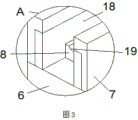
FIG. 3 is an enlarged view of the utility model at A in FIG. 1;
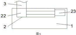
FIG. 4 is a schematic diagram of a displacement mechanism according to the present utility model.
Legend description:
1. a base; 2. a displacement groove; 3. a movable frame; 4. a hydraulic rod; 5. a pressing plate; 6. a fixing seat; 7. a limiting plate; 8. a movable seat; 9. a movable groove; 10. a transmission block; 11. a transmission groove; 12. a drive rack; 13. a transmission shaft; 14. tooth slots; 15. a screw groove; 16. a return spring; 17. a torsion spring shaft; 18. a sponge cushion; 19. a positioning groove; 20. a pressure sensitive weighing machine; 21. a support rod; 22. a slide block; 23. a pneumatic telescopic rod.
Detailed Description
The following description of the embodiments of the present utility model will be made clearly and completely with reference to the accompanying drawings, in which it is apparent that the embodiments described are only some embodiments of the present utility model, but not all embodiments. All other embodiments, which can be made by those skilled in the art based on the embodiments of the utility model without making any inventive effort, are intended to be within the scope of the utility model.
Examples: the utility model provides a test machine for detecting carbon fiber bicycle frames, as shown in figures 1 to 3, the test machine comprises a base 1, movable frames 3 are movably arranged at the top of the base 1, the movable frames 3 are of rectangular structures, hydraulic rods 4 are fixedly arranged at the top of the movable frames 3, a pressing plate 5 is fixedly arranged at the bottom of the output end of each hydraulic rod 4, a fixed seat 6 is arranged on the right side of the top of the base 1, the fixed seat 6 is of a cylindrical rectangular structure, a limiting mechanism is arranged on the fixed seat 6 and comprises limiting plates 7, movable seats 8, movable grooves 9, a transmission block 10, a transmission groove 11, transmission racks 12 and transmission shafts 13, the limiting plates 7 are two plates of rectangular structures, the two limiting plates 7 are arranged on the top wall surface of the fixed seat 6 in a left-right mode, the limiting plate 7 fixed mounting that is located the left side is at the top of fixing base 6, movable seat 8 is the piece of rectangle structure, movable seat 8 sets up between two limiting plates 7, movable groove 9 is the groove of rectangle structure, movable groove 9 sets up on the top right side of fixing base 6, transmission piece 10 movable mounting is in the inside of movable groove 9, the limiting plate 7 fixed mounting that is located the right side is at the top of transmission piece 10, the position of movable seat 8 is corresponding at the top of fixing base 6 is seted up to transmission groove 11, transmission rack 12 movable mounting is in the inside of transmission groove 11, transmission rack 12 and the bottom wall fixed connection of movable seat 8, horizontal movable mounting is in the inside of fixing base 6 about transmission shaft 13.
The transmission shaft 13 is provided with a tooth groove 14 corresponding to the position of the transmission rack 12, the right side of the transmission shaft 13 is provided with a screw groove 15, the transmission shaft 13 is meshed with the transmission rack 12 through the tooth groove 14, the right side of the transmission shaft 13 penetrates through the left side wall and the right side wall of the transmission block 10 and is in threaded connection with the transmission block 10 through the screw groove 15, the inside of the transmission groove 11 is movably provided with a reset spring 16 fixedly connected with the transmission rack 12, the inside of the fixed seat 6 is movably provided with a torsion spring shaft 17, and the torsion spring shaft 17 is fixedly connected with the transmission shaft 13.
The sponge cushion 18 is embedded and installed on the side wall surface of the two limit plates 7, the locating groove 19 is formed in the top of the movable seat 8, and the locating groove 19 is of an arc-shaped structure.
The top of the base 1 is embedded with a pressure-sensitive weighing machine 20, the fixed seat 6 is fixedly arranged on the top wall surface of the pressure-sensitive weighing machine 20, the supporting rods 21 are fixedly arranged above the fixed seat 6 at four corners of the top wall surface of the pressure-sensitive weighing machine 20 in an inclined mode, the supporting rods 21 are rods in rectangular structures, and the bottoms of the supporting rods 21 are fixedly connected with the upper portion of the fixed seat 6.
The base 1 is provided with a displacement mechanism for driving the movable frame 3 to move, the displacement mechanism comprises two displacement grooves 2, sliding blocks 22 and a pneumatic telescopic rod 23, the two displacement grooves 2 are respectively formed in two sides of the top of the base 1, the two sliding blocks 22 are respectively movably mounted in the two displacement grooves 2, the pneumatic telescopic rod 23 is mounted in the base 1 in an embedded mode at a position corresponding to the displacement grooves 2, and the output end of the pneumatic telescopic rod 23 is fixedly connected with the sliding blocks 22.
The working principle of the utility model is as follows:
when the bicycle frame to be tested is placed on the fixed seat 6 in use, the bicycle frame can be automatically fixed on the fixed seat 6 through the limiting mechanism on the fixed seat 6, and then the hydraulic rod 4 can drive the pressing plate 5 to press the bicycle frame downwards, so that the strength data of the bicycle frame are obtained, the effect that the bicycle frame can be automatically fixed is achieved, and the detection efficiency is improved.
The bicycle frame is placed on the movable seat 8, the movable seat 8 is driven to move downwards, the transmission rack 12 is driven to move by the movable seat 8, the transmission rack 12 is directly meshed with the transmission shaft 13 through the tooth grooves 14, the transmission shaft 13 is rotated by the movement of the transmission rack 12, the transmission shaft 13 is meshed with the transmission block 10 through the spiral grooves 15, the transmission block 10 is driven to move by the rotation of the transmission shaft 13 to move the limiting plate 7 positioned on the right side, and the bicycle frame is fixed and positioned between the movement of the limiting plate 7 and the other limiting plate 7.
Because be provided with the pressure sensing weighing machine 20 on the base 1, fixing base 6 sets up on the pressure sensing weighing machine 20, when the bicycle frame put on fixing base 6 back, the pressure sensing weighing machine 20 will weigh the bicycle frame on the fixing base 6 to obtain the weight data of bicycle frame, hydraulic stem 4 is when carrying out intensity test to the bicycle frame simultaneously, and the pressure sensing weighing machine 20 also receives the intensity that hydraulic stem 4 exerted force, and then has reached the effect that makes the test result more accurate.
The foregoing has shown and described the basic principles and main features of the present utility model and the advantages of the present utility model. It will be understood by those skilled in the art that the present utility model is not limited to the embodiments described above, and that the above embodiments and descriptions are merely illustrative of the principles of the present utility model, and various changes and modifications may be made without departing from the spirit and scope of the utility model, which is defined in the appended claims. The scope of the utility model is defined by the appended claims and equivalents thereof.
Claims (6)
1. The utility model provides a detect test machine of carbon fiber bicycle frame, includes base (1), its characterized in that: the top of the base (1) is movably provided with a movable frame (3), the top of the movable frame (3) is fixedly provided with a hydraulic rod (4), the bottom of the output end of the hydraulic rod (4) is fixedly provided with a pressing plate (5), the right side of the top of the base (1) is provided with a fixed seat (6), the fixed seat (6) is provided with a limiting mechanism, the limiting mechanism comprises a limiting plate (7), a movable seat (8), a movable groove (9), a transmission block (10), a transmission groove (11), a transmission rack (12) and a transmission shaft (13), the number of the limiting plates (7) is two, the two limiting plates (7) are arranged on the left and right sides of the top of the fixed seat (6), the limiting plate (7) positioned on the left side is fixedly arranged on the top of the fixed seat (6), the movable seat (8) is arranged between the two limiting plates (7), the movable groove (9) is arranged on the right side of the top of the fixed seat (6), the transmission block (10) is movably arranged in the movable groove (9), the limiting plate (7) positioned on the right side is fixedly arranged on the top of the transmission block (10), the transmission groove (11) is correspondingly arranged in the transmission groove (11) of the fixed seat (8), the transmission rack (12) is fixedly connected with the bottom wall surface of the movable seat (8), and the transmission shaft (13) is transversely and movably arranged in the fixed seat (6) left and right.
2. The tester for detecting a carbon fiber bicycle frame according to claim 1, wherein: tooth grooves (14) are formed in positions, corresponding to the transmission racks (12), on the transmission shafts (13), screw grooves (15) are formed in the right sides of the transmission shafts (13), the transmission shafts (13) are meshed with the transmission racks (12) through the tooth grooves (14), the right sides of the transmission shafts (13) penetrate through the left side wall and the right side wall of the transmission block (10) and are in threaded connection with the transmission block (10) through the screw grooves (15), reset springs (16) fixedly connected with the transmission racks (12) are movably mounted in the transmission grooves (11), torsion spring shafts (17) are movably mounted in the fixing seats (6), and the torsion spring shafts (17) are fixedly connected with the transmission shafts (13).
3. The tester for detecting a carbon fiber bicycle frame according to claim 1, wherein: the sponge pads (18) are embedded and installed on the side wall surfaces of the two limit plates (7) which are close to each other, and the top of the movable seat (8) is provided with a positioning groove (19).
4. The tester for detecting a carbon fiber bicycle frame according to claim 1, wherein: the top of base (1) is inlayed and is provided with pressure sensing weighing machine (20), fixing base (6) fixed mounting is at the top wall of pressure sensing weighing machine (20).
5. The tester for detecting a carbon fiber bicycle frame according to claim 4, wherein: the four corners of the top wall surface of the pressure sensing weighing machine (20) are respectively and fixedly provided with a supporting rod (21) above the inclined fixing seat (6), and the bottom of the supporting rod (21) is fixedly connected with the upper part of the fixing seat (6).
6. The tester for detecting a carbon fiber bicycle frame according to claim 1, wherein: the base (1) is provided with a displacement mechanism for driving the movable frame (3) to move, the displacement mechanism comprises two displacement grooves (2), sliding blocks (22) and pneumatic telescopic rods (23), the two displacement grooves (2) are respectively formed in the two sides of the top of the base (1), the two sliding blocks (22) are respectively movably mounted in the two displacement grooves (2), the pneumatic telescopic rods (23) are mounted in the base (1) at positions corresponding to the displacement grooves (2) in an inlaid mode, and the output ends of the pneumatic telescopic rods (23) are fixedly connected with the sliding blocks (22).
Priority Applications (1)
| Application Number | Priority Date | Filing Date | Title |
|---|---|---|---|
| CN202223108468.1U CN218973837U (en) | 2022-11-22 | 2022-11-22 | Tester for detecting carbon fiber bicycle frame |
Applications Claiming Priority (1)
| Application Number | Priority Date | Filing Date | Title |
|---|---|---|---|
| CN202223108468.1U CN218973837U (en) | 2022-11-22 | 2022-11-22 | Tester for detecting carbon fiber bicycle frame |
Publications (1)
| Publication Number | Publication Date |
|---|---|
| CN218973837U true CN218973837U (en) | 2023-05-05 |
Family
ID=86152071
Family Applications (1)
| Application Number | Title | Priority Date | Filing Date |
|---|---|---|---|
| CN202223108468.1U Active CN218973837U (en) | 2022-11-22 | 2022-11-22 | Tester for detecting carbon fiber bicycle frame |
Country Status (1)
| Country | Link |
|---|---|
| CN (1) | CN218973837U (en) |
-
2022
- 2022-11-22 CN CN202223108468.1U patent/CN218973837U/en active Active
Similar Documents
| Publication | Publication Date | Title |
|---|---|---|
| CN218973837U (en) | Tester for detecting carbon fiber bicycle frame | |
| CN207019890U (en) | A kind of seat chair back durability test machine | |
| CN110726466B (en) | Multi-station creep calibration device and method | |
| CN106644329B (en) | 120MN bridge support testing machine for high-precision dynamic measurement | |
| CN210005164U (en) | multi-component force sensor calibration machine | |
| CN209927434U (en) | Novel multistation spring draws presses test machine | |
| CN217359383U (en) | Structural mechanical property testing device | |
| CN210347123U (en) | Spring check out test set is used in spring production | |
| CN211452693U (en) | Push-pull force measuring device of straight-stroke actuator | |
| CN219912506U (en) | Environmental monitor supporting device for environmental monitoring | |
| CN109141840B (en) | Wedge-shaped locking device test bed | |
| CN109374521B (en) | Device for testing friction energy consumption performance of metal rubber and working method thereof | |
| CN220982143U (en) | Part height testing device | |
| CN218974058U (en) | De Mo Xi subtest machine | |
| CN221976594U (en) | Material bending property tester | |
| CN218673466U (en) | Detection tool for automobile flange symmetry | |
| CN221686166U (en) | Rolling load tester for stadium wood floor | |
| CN219757157U (en) | Detection clamp for measuring height of protruding surface of rivet | |
| CN221992611U (en) | Plank roughness check out test set is used in furniture production | |
| CN215811363U (en) | Novel dynamometry unit | |
| CN215573323U (en) | Weighing device for detection equipment | |
| CN213516618U (en) | Bed support hardware bearing capacity detection device | |
| CN216208168U (en) | Device for measuring softness, stiffness and roughness of flexible material | |
| CN219946496U (en) | Plastic pipe processing cutting equipment | |
| CN215810551U (en) | Mechanical measuring equipment convenient to use |
Legal Events
| Date | Code | Title | Description |
|---|---|---|---|
| GR01 | Patent grant | ||
| GR01 | Patent grant |