CN218953429U - Motorcycle - Google Patents
Motorcycle Download PDFInfo
- Publication number
- CN218953429U CN218953429U CN202222928381.2U CN202222928381U CN218953429U CN 218953429 U CN218953429 U CN 218953429U CN 202222928381 U CN202222928381 U CN 202222928381U CN 218953429 U CN218953429 U CN 218953429U
- Authority
- CN
- China
- Prior art keywords
- gear
- clutch
- motorcycle
- engine
- shaft
- Prior art date
- Legal status (The legal status is an assumption and is not a legal conclusion. Google has not performed a legal analysis and makes no representation as to the accuracy of the status listed.)
- Active
Links
Images


Abstract
The application relates to the technical field of motorcycles, in particular to a motorcycle, which comprises an engine, wherein the engine comprises: the transmission mechanism comprises a crankshaft and a balance shaft, and the crankshaft is in transmission connection with the balance shaft; the speed change mechanism comprises a main shaft and a secondary shaft, the main shaft is in transmission connection with the crankshaft, and the main shaft is in transmission connection with the secondary shaft; the clutch comprises a clutch gearwheel which is arranged on the main shaft; the transmission mechanism further comprises an output gear and a balance gear, the output gear is arranged on the crankshaft, the balance gear is arranged on the balance shaft, and the output gear is meshed with the balance gear and the clutch gear wheel at the same time so as to drive the balance gear and the clutch gear wheel at the same time. According to the engine, the components of the engine are simplified in advance without affecting the original functions of the engine, so that the weight of the engine is reduced, the occupied space is effectively reduced, more degrees of freedom are given to the engine to be mounted on the motorcycle, and the light-weight requirement of the motorcycle is further met.
Description
Technical Field
The application relates to the technical field of motorcycles, in particular to a motorcycle.
Background
At present, the demand for weight reduction of motorcycles is increasing, so that the space of the motorcycle is smaller, the space for installing an engine is also smaller, and the engine on the market is difficult to be adapted to a novel weight-reduced motorcycle.
An engine is a machine capable of converting other forms of energy into mechanical energy, such as an internal combustion engine (gasoline engine, etc.), an external combustion engine (stirling engine, steam engine, etc.), an electric motor, etc. At present, the number of engine parts in the market is large, so that the weight and the volume of the engine are large, and the requirement of the market on the light weight of the motorcycle is difficult to meet.
Disclosure of Invention
Accordingly, there is a need for a motorcycle that has simplified engine components, reduced weight, and reduced space occupation, and meets the need for weight reduction.
Aiming at the technical problems, the application provides the following technical scheme:
a motorcycle, the motorcycle comprising: a frame; the walking system comprises a front wheel assembly and a rear wheel assembly; the suspension system is connected to the frame through the walking system; an engine driving the traveling system, the engine comprising: the transmission mechanism comprises a crankshaft and a balance shaft, and the crankshaft is in transmission connection with the balance shaft; the speed change mechanism comprises a main shaft and a secondary shaft, the main shaft is in transmission connection with the crankshaft, and the main shaft is in transmission connection with the secondary shaft; the clutch comprises a clutch gearwheel which is arranged on the main shaft; the transmission mechanism further comprises an output gear and a balance gear, the output gear is arranged on the crankshaft, the balance gear is arranged on the balance shaft, and the output gear is meshed with the balance gear and the clutch gear wheel at the same time so as to drive the balance gear and the clutch gear wheel at the same time.
Further, the center distance between the output gear and the clutch large gear is 115 mm-120 mm.
Further, a first plane is defined by the axis of the main shaft and the axis of the crankshaft, a third plane is defined by the axis of the auxiliary shaft and the axis of the crankshaft, and an angle between the third plane and the first plane is α, and 19 ° < α <23 °.
Further, the engine further comprises a cylinder block, the cylinder block comprises a first cylinder body and a second cylinder body, and the first mounting hole is formed in the first cylinder body; the first cylinder body is provided with a first splicing surface, and the second cylinder body is provided with a second splicing surface; wherein, set up first mounting groove on the first concatenation face, set up the second mounting groove on the second concatenation face, first mounting groove and the aligned concatenation of second mounting groove form the second mounting hole.
Further, the first cylinder body is provided with a containing groove which is used for installing the clutch gear; the first mounting hole is communicated with the accommodating groove, a connecting part is arranged between the accommodating groove and the first mounting groove, and an assembly hole is formed in the connecting part; the cylinder body further comprises a connecting piece, and the connecting piece is inserted into the assembly hole to connect the first cylinder body and the second cylinder body.
Further, the clutch shaft sleeve comprises a body and a clamping part, wherein the clamping part is arranged on the body and can be matched with the clamp for disassembling or assembling the body.
Further, an avoidance groove is formed in the clutch shaft sleeve, and the clamping part is arranged in the avoidance groove.
Further, the engine further includes: the engine oil pump driving gear is provided with a first positioning hole extending along the axial direction of the engine oil pump driving gear, the clutch gear is provided with a second positioning hole extending along the axial direction of the clutch gear, and the first positioning hole corresponds to the second positioning hole during assembly; the positioning piece is inserted into the first positioning hole and the second positioning hole at the same time and used for limiting the circumferential rotation of the oil pump driving gear relative to the clutch gear.
Further, the positioning member is provided as a pin.
Compared with the prior art, the motorcycle provided by the application has the advantages that through simplifying the parts in the engine, namely, the clutch large gear and the balance gear are directly driven simultaneously through the output gear, the balance driving wheel and the balance driven wheel are not required to be additionally arranged, so that the weight of the engine is reduced in advance without affecting the original function of the engine, the occupied space is obviously reduced, more degrees of freedom are provided for the engine to be mounted on the motorcycle, and the light-weight requirement of the motorcycle is further realized.
Drawings
In order to more clearly illustrate the technical solutions of embodiments or conventional techniques of the present application, the drawings that are required to be used in the description of the embodiments or conventional techniques will be briefly described below, and it is apparent that the drawings in the following description are only some embodiments of the present application, and other drawings may be obtained according to these drawings without inventive effort for a person of ordinary skill in the art.
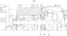
FIG. 1 is a schematic diagram of the distribution of the shaft systems inside an engine according to an embodiment of the present application.
Fig. 2 is a cross-sectional view A-A of fig. 1.
Fig. 3 is a schematic view of a spindle installed in a cylinder body according to an embodiment of the present application.
Fig. 4 is a schematic structural view of a first cylinder in an embodiment of the present application.
Fig. 5 is a schematic view of a spindle and bearing housing assembly in an embodiment of the present application.
Fig. 6 is a schematic view of a clutch gear wheel according to an embodiment of the present application assembled on a cylinder block.
Fig. 7 is a right side view of fig. 6.
Fig. 8 is an exploded view of fig. 6.
Fig. 9 is a schematic view of a sleeve provided in an embodiment of the present application.
Fig. 10 is a sectional view of the main shaft mounted in the first cylinder body through the bearing housing.
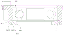
Fig. 11 is a schematic view of a bearing housing provided in an embodiment of the present application.
Fig. 12 is a cross-sectional view of the bearing housing of fig. 11.
Fig. 13 is a cross-sectional view of a spindle mounted in a first cylinder through a bearing housing in another embodiment.
Fig. 14 is a schematic view of a bearing housing provided in another embodiment of the present application.
Fig. 15 is a cross-sectional view of the bearing housing of fig. 14.
Fig. 16 is a schematic diagram of an assembly of a clutch gear and an oil pump driving gear according to an embodiment of the present application.
Fig. 17 is an exploded view of fig. 16.
Fig. 18 is a cross-sectional view of the clutch large gear and oil pump drive gear assembly of fig. 16.
Fig. 19 is a schematic structural view of a camshaft provided in an embodiment of the present application.
Fig. 20 is a schematic structural view of a valve train according to an embodiment of the present disclosure.
Fig. 21 is a B-B sectional view of fig. 20.
Fig. 22 is a schematic structural view of a motorcycle provided in an embodiment of the present application.
Reference numerals: 1000. a motorcycle; 100. an engine; 10. a body group; 11. a cylinder head cover; 12. a cylinder block; 121. a first cylinder; 1211. a first splicing surface; 122. a second cylinder; 1221. a second splicing surface; 123. a first mounting hole; 124. a second mounting hole; 1241. a first mounting groove; 1242. a second mounting groove; 125. a receiving groove; 126. a connection part; 127. a fitting hole; 128. a connecting piece; 13. a cylinder head; 14. an oil pan; 20. a transmission mechanism; 21. a crankshaft; 22. a balance shaft; 23. an output gear; 24. a balance gear; 30. a speed change mechanism; 31. a main shaft; 32. a secondary shaft; 33. a variable speed drive gear; 34. a variable speed driven gear; 35. a mounting gap; 36. a bearing seat; 361. a base; 3611. a through hole; 3612. a second threaded portion; 3613. a limit part; 3614. a step surface; 362. a limiting piece; 3621. a ring structure; 36211. a first threaded portion; 3622. a limiting plate; 36221. an annular plate body; 36222. a connecting lug; 363. a fastener; 37. a bearing; 40. a clutch; 41. a clutch gear; 411. a second positioning hole; 50. a shaft sleeve; 51. a body; 52. a clamping part; 53. an avoidance groove; 60. a lubrication system; 61. an oil pump driving gear; 611. a first positioning hole; 62. a positioning piece; 63. an oil pump gear; 70. a valve train; 71. a cam shaft; 711. an adjusting section; 712. an edge; 72. valve clearance; 200. a frame; 300. a walking system; 300a, a front wheel assembly; 300b, rear wheel assembly; 400. a suspension system.
Detailed Description
In order to make the above objects, features and advantages of the present application more comprehensible, embodiments accompanied with figures are described in detail below. In the following description, numerous specific details are set forth in order to provide a thorough understanding of the present application. This application is, however, susceptible of embodiment in many other forms than those described herein and similar modifications can be made by those skilled in the art without departing from the spirit of the application, and therefore the application is not to be limited to the specific embodiments disclosed below.
It will be understood that when an element is referred to as being "mounted" or "disposed" on another element, it can be directly on the other element or intervening elements may also be present. When a component is considered to be "connected" to another component, it can be directly connected to the other component or intervening components may also be present. The terms "vertical," "horizontal," "upper," "lower," "left," "right," and the like are used in the description of the present application for purposes of illustration only and do not represent the only embodiment.
Furthermore, the terms "first," "second," and the like, are used for descriptive purposes only and are not to be construed as indicating or implying a relative importance or implicitly indicating the number of technical features indicated. Thus, a feature defining "a first" or "a second" may explicitly or implicitly include at least one such feature. In the description of the present application, the meaning of "plurality" is at least two, such as two, three, etc., unless explicitly defined otherwise.
In this application, unless expressly stated or limited otherwise, a first feature "up" or "down" a second feature may be a direct contact of the first feature with the second feature, or an indirect contact of the first feature with the second feature via an intervening medium. Moreover, a first feature being "above," "over" and "on" a second feature may be a first feature being directly above or obliquely above the second feature, or simply indicating that the first feature is higher in level than the second feature. The first feature being "under", "below" and "beneath" the second feature may be the first feature being directly under or obliquely under the second feature, or simply indicating that the first feature is less level than the second feature.
Unless defined otherwise, all technical and scientific terms used in the specification of this application have the same meaning as commonly understood by one of ordinary skill in the art to which this application belongs. The terminology used in the description of the present application is for the purpose of describing particular embodiments only and is not intended to be limiting of the present application. The term "and/or" as used in the specification of this application includes any and all combinations of one or more of the associated listed items.
As shown in fig. 22, an embodiment of the present application provides a motorcycle 1000, the motorcycle 1000 including a frame 200, a running system 300, a suspension system 400, and an engine 100, wherein the running system 300 includes a front wheel assembly 300a and a rear wheel assembly 300b, and the running system 300 is connected to the frame 200 through the suspension system 400, and the engine 100 is used to drive the running system 300 to move. In the embodiment of the present application, the motorcycle 1000 may be a two-wheeled motorcycle, or may be a three-wheeled or four-wheeled motorcycle.
In another embodiment of the present application, an engine 100 is provided, the engine 100 being used in a motorcycle 1000. The engine 100 is mainly composed of a block 10, a valve train 70, a transmission system, a fuel supply system, an ignition system, a cooling system, a lubrication system 60, a starting system, and the like.
The engine block 10 includes a cylinder head cover 11, a cylinder head 13, a cylinder block 12 (i.e., crankcase), and an oil pan 14, the cylinder head 13 being provided on the cylinder block 12, the cylinder head cover 11 being provided on the cylinder head 13, the oil pan 14 being provided at the bottom of the cylinder block 12 for collecting engine oil flowing back inside the engine 100 and storing engine oil of the engine 100.
As shown in fig. 1 and 2, the transmission system includes a transmission mechanism 20, the transmission mechanism 20 including a crankshaft 21 and a balance shaft 22, the crankshaft 21 and the balance shaft 22 being drivingly connected, the crankshaft 21 converting a force of the fuel gas acting on the body thereof into a torque of the crankshaft 21 to output power.
With continued reference to fig. 1 and 2, the transmission mechanism 20 further includes an output gear 23 and a balance gear 24, wherein the output gear 23 is disposed on the crankshaft 21, the balance gear 24 is disposed on the balance shaft 22, the output gear 23 is meshed with the balance gear 24, and the crankshaft 21 and the balance shaft 22 are in gear engagement transmission.
With continued reference to fig. 1 and 2, the transmission system further includes a speed change mechanism 30 and a clutch 40, the clutch 40 includes a clutch gear 41, the speed change mechanism 30 includes a main shaft 31, a countershaft 32, and a plurality of sets of speed change driving gears 33 and a plurality of sets of speed change driven gears 34, the crankshaft 21 is located between the main shaft 31 and the balance shaft 22, and the countershaft 32 is located on a side of the main shaft 31 away from the crankshaft 21; the clutch large gear 41 is provided at an end of the main shaft 31 and is capable of meshing with the output gear 23, thereby transmitting power of the crankshaft 21 to the main shaft 31; the multiple groups of variable speed driving gears 33 are arranged on the main shaft 31, the multiple groups of variable speed driven gears 34 are arranged on the auxiliary shaft 32, and when the variable speed driving gears 33 are meshed with different variable speed driven gears 34 to drive power, the rotation speed ratio of the main shaft 31 to the auxiliary shaft 32 can be changed, so that the speed change is realized.
As shown in fig. 1 and 2, the axis of the main shaft and the axis of the crankshaft define a first plane, the axis of the main shaft and the axis of the auxiliary shaft define a second plane, an included angle θ is formed between the first plane and the second plane, and 0 ° < θ <180 °, so that the main shaft is respectively arranged in a dislocation manner with the crankshaft and the auxiliary shaft, so that the space along the width direction of the cylinder block 12 can be reduced, the layout of each shaft is more compact, the size of the engine 100 along the width direction of the cylinder block 12 is further reduced, the occupied space is smaller, and more degrees of freedom are provided for mounting each component on a motorcycle.
In an embodiment, the included angle θ between the first plane and the second plane is set to be 114 ° to 124 °, and an excessively small included angle θ may cause motion interference between the main shaft 31 and the crankshaft 21, and an excessively large included angle θ may cause an excessively large occupied space for installing each shaft system, thereby causing an excessively large volume of the cylinder block 12, which violates the requirement of light weight. Therefore, the included angle θ is controlled to be 114 ° to 124 °, and the requirement of light weight is satisfied while ensuring normal movement of the crankshaft 21.
More preferably, the included angle θ between the first plane and the second plane is set to 119 °, although in other embodiments, the included angle θ may be 114 °, 115 °, 118 °, 122 °, 123 °, 124 °, and the like.
As shown in fig. 1, the axis of the auxiliary shaft 32 and the axis of the crankshaft 21 determine a third plane, and an included angle between the third plane and the first plane is α, and 19 ° < α <23 °, so that the distance between the main shaft 31 and the crankshaft 21 in the height direction is balanced, and the distance between the crankshaft 21 and the auxiliary shaft 32 in the horizontal direction is balanced, so that the dimensions of the engine in the width direction and the length direction are considered, and the requirement of light weight is considered on the premise of realizing the engine function.
Preferably, in this embodiment, the number of the balance gears 24 is one, and the output gear 23 is directly meshed with the balance gears 24 to drive the balance gears 24 to move, thereby driving the balance shaft 22 to rotate. Compared with the prior art, the driving wheel and the driven wheel for driving the balance shaft 22 do not need to be specially arranged, so that the arrangement of the embodiment reduces occupied space, simultaneously effectively reduces the weight of the engine 100, realizes the light-weight requirement and reduces carbon emission.
As shown in fig. 1 and 2, since the balance gear 24 and the clutch large gear 41 are simultaneously driven by the output gear 23 in the present embodiment, the sliding force of the engagement between the output gear 23 and the balance gear 24 is F1, the sliding force of the engagement between the output gear 23 and the clutch large gear 41 is F2, F1 is different from F2, and thus the balance of F1 and F2 is required at the time of setting, for which reason, in the present embodiment, the center distance L between the output gear 23 and the clutch large gear 41 is in the range of 115mm to 120mm to ensure that the sliding force F1 and the sliding force F2 meet the requirements, so that the output gear 23 can simultaneously drive the balance gear 24 and the clutch large gear 41.
In one embodiment, as shown in fig. 1, the crankshaft 21, the balance shaft 22 and the auxiliary shaft 32 are relatively flush, and the main shaft 31 is relatively located above the locating plane, in other words, in the height direction of the motorcycle, the main shaft 31 is higher than the crankshaft 21, the balance shaft 22 and the auxiliary shaft 32, and the heights of the crankshaft 21, the balance shaft 22 and the auxiliary shaft 32 are substantially the same, so as to adjust the structure of the cylinder block 12 and the layout of other internal components, and avoid the structural modification of the cylinder block 12 as much as possible.
As shown in fig. 1 and 3, the cylinder block 12 is provided with a first mounting hole 123 and a plurality of second mounting holes 124, wherein the first mounting hole 123 is used for supporting and positioning the main shaft 31, and the plurality of second mounting holes 124 are used for supporting and positioning the auxiliary shaft 32, the balance shaft 22 and the crankshaft 21, respectively. At the time of installation, the main shaft 31 is inserted into the cylinder block 12 through the first installation hole 123, and the end of the main shaft 31 is restricted in the first installation hole 123.
As shown in fig. 1 and 3, in the case where the installation heights corresponding to the crankshaft 21, the counter shaft 32, and the balance shaft 22 are substantially the same, the cylinder block 12 includes a first cylinder block 121 and a second cylinder block 122, the first cylinder block 121 has a first mating surface 1211 thereon, and the second cylinder block 122 has a second mating surface 1221 thereon, and the first mating surface 1211 is aligned with the second mating surface 1221 so that the first cylinder block 121 and the second cylinder block 122 are mated to form the cylinder block 12. The first splicing surface 1211 is provided with a first mounting groove 1241, the second splicing surface 1221 is provided with a second mounting groove 1242, and the first mounting groove 1241 and the second mounting groove 1242 are spliced to form a second mounting hole 124 during splicing, so that the auxiliary shaft 32, the crankshaft 21 and the balance shaft 22 are arranged in the cylinder block 12 and are positioned and limited through the corresponding second mounting hole 124, the installation is simple and convenient, the arrangement scheme of the crankshaft 21, the balance shaft 22 and the auxiliary shaft 32 has less structural change on the cylinder block 12, the cylinder block 12 is divided into the first cylinder body 121 and the second cylinder body 122, the first cylinder body 121 and the second cylinder body 122 can be manufactured respectively, and the processing rate is improved. Specifically, for example, as shown in fig. 1 and 3, when the crankshaft 21 is mounted, both ends of the crankshaft 21 are respectively installed in the corresponding first mounting grooves 1241 of the first cylinder block 121, the second cylinder block 122 is covered on the first cylinder block 121, and the second mounting grooves 1242 supporting the crankshaft 21 are made to correspond to the corresponding first mounting grooves 1241, so that the crankshaft 21 is positioned and limited by the first mounting grooves 1241 and the second mounting grooves 1242.
As shown in fig. 3, 4 and 8, the first cylinder block 12 is provided with a receiving groove 125, the first mounting hole 123 communicates with the receiving groove 125, and the clutch gear 41 is mounted in the receiving groove 125 and located at an end of the main shaft 31.
With continued reference to fig. 6 and 8, a connecting portion 126 is disposed between the accommodating groove 125 and the first mounting groove 1241, and an assembly hole 127 is formed at the connecting portion 126; the cylinder block 12 further includes a connecting member 128, and the connecting member 128 is inserted into the fitting hole 127 to connect the first cylinder block 121 and the second cylinder block 122. Specifically, the connecting member 128 is provided as a fastening structure such as a bolt or a screw, and when the first cylinder 121 is mounted, the first cylinder 122 is aligned with the second cylinder 122, and the connecting member 128 is inserted into the mounting hole 127 to fasten the first cylinder 121 and the second cylinder 122.
Referring to fig. 5 to 8, the transmission system further includes a clutch sleeve 50, the clutch 40 is sleeved on the main shaft 31, the clutch sleeve 50 is located between the main shaft 31 and the clutch 40, and the clutch sleeve 50 is used for accommodating and connecting the main shaft 31, so that the main shaft 31 stably rotates and transmitting an axial force of the main shaft 31 to the clutch 40.
With continued reference to fig. 6 to 8, since the output gear 23 of the present application drives the balance gear 24 and the clutch gear 41 at the same time, in order to ensure that the sliding force between the output gear 23 and the clutch gear 41 meets the requirement, in this embodiment, the diameter of the clutch gear 41 is increased, the clutch gear 41 can be just installed in the accommodating groove 125 when installed, due to the limitation of the cylinder block 12 structure, no active space can be reserved between the clutch gear 41 and the accommodating groove 125, and the connection portion 126 between the clutch gear 41 and the cylinder block 12 interferes, so that the clutch gear 41 and the clutch sleeve 50 cannot be assembled into a whole during installation and then installed in the accommodating groove 125. In this embodiment, there is a mounting gap 35 between the clutch gear 41 and the main shaft 31, the mounting gap 35 is used for mounting the clutch sleeve 50, when mounting, the clutch gear 41 is first sleeved on the main shaft 31, and then the clutch gear 41 is adjusted to move radially, so that the clutch gear 41 avoids the connecting portion 126 and is smoothly mounted in the accommodating groove 125, and then the clutch sleeve 50 is mounted between the main shaft 31 and the clutch gear 41, wherein the mounting gap 35 provides a moving space for radial movement of the clutch gear 41.
The shaft sleeve 50 in the prior art has no clamping part 52, so that the purpose of firstly installing the clutch gear wheel 41 and then installing the clutch shaft sleeve 50 cannot be achieved, and the clutch shaft sleeve 50 and the clutch gear wheel 41 cannot be respectively detached during the detachment, therefore, as shown in fig. 8 and 9, the embodiment provides a shaft sleeve 50 structure, the shaft sleeve 50 structure comprises a body 51 and the clamping part 52, and the shaft sleeve 50 structure is installed between an assembled rotor and a rotating shaft by matching a clamp such as pliers with the clamping part 52 during the installation or the detachment of the shaft sleeve 50 structure, and can also be detached before the rotor by the clamp during the detachment. In this embodiment, the clutch sleeve 50 is configured as the sleeve 50, during assembly, the clutch gear 41 is first mounted in the accommodating groove 125, then the clutch sleeve 50 is mounted between the clutch gear 41 and the spindle 31 by matching the clamp with the clamping portion 52, and similarly, during disassembly, in order to avoid the connecting portion 126, the clutch sleeve 50 is first disassembled by matching the clamp with the clamping portion 52, leaving the mounting gap 35 free, and then the clutch gear 41 is disassembled, so that the clutch gear 41 can adjust its position through the mounting gap 35. The clamping part 52 is arranged on the clutch shaft sleeve 50 to solve the problem of installation interference of the clutch large gear 41, and the cylinder body 12 does not need to be changed and enlarged to adapt to the change of the volume of the clutch large gear 41, so that the improvement cost is reduced, the cylinder body 12 is prevented from becoming large, and the requirement of light weight is met.
As shown in fig. 9, the clamping portion 52 is a protrusion, the protrusion is provided on the body 51, and the protrusion is provided to extend in the axial direction of the clutch collar 50, so that the clutch collar 50 can be mounted or dismounted by clamping the protrusion with pliers when the clutch collar 50 is mounted or dismounted, which is time-saving and labor-saving. Of course, in other embodiments, the specific structure of the clamping portion 52 is not limited to that described above or shown in the drawings, for example, a clamping groove may be formed on the periphery of the protruding portion, so that the pliers can be matched with the clamping groove when clamping the protruding portion, that is, at least a portion of the pliers abuts against the clamping groove to realize the limit of the pliers, so as to prevent the pliers from unstable clamping or sliding out of the pliers due to insufficient friction force when clamping the protruding portion.
With continued reference to fig. 9, the clutch shaft sleeve 50 is provided with a avoidance groove 53, and the clamping portion 52 is disposed in the avoidance groove 53, so that the clamping portion 52 can be prevented from extending out of the clutch shaft sleeve 50 to interfere with other structures to affect the installation of other structures, and the avoidance groove 53 is provided to reduce the weight of the clutch shaft sleeve 50 without affecting the rotation of the clutch gear 41, thereby realizing the light-weight requirement.
As shown in fig. 9, the number of the clamping parts 52 is two, and the two clamping parts 52 are symmetrically arranged about the axis of the clutch sleeve 50, so that the clamping parts 52 are simultaneously clamped by two pliers when the clutch sleeve 50 is mounted or dismounted, the clutch sleeve 50 is prevented from tilting, and thus, the clutch sleeve 50 can be mounted and dismounted rapidly and stably. Of course, in other embodiments, the number of the clamping portions 52 provided is not limited to the above, and for example, one, three, four, and the like may be provided.
As shown in fig. 10 to 15, the transmission mechanism 20 further includes a bearing housing 36 and a bearing 37, the bearing 37 is provided in the bearing housing 36, the bearing housing 36 is provided in the first mounting hole 123, and the end of the main shaft 31 is mounted in the bearing 37. Wherein, bearing frame 36 is used for filling the clearance between first mounting hole 123 and bearing 37 to make main shaft 31 installation stable, avoid producing the noise. The bearing 37 is assembled with the bearing housing 36 at the time of installation, and then installed in the first installation hole 123.
As shown in fig. 11 and 15, the bearing seat 36 includes a seat body 361 and a limiting member 362, a through hole 3611 is formed in the seat body 361 along an axial direction of the seat body 361, a limiting portion 3613 extending along an inner side of the seat body 361 is provided at one end of the seat body 361 for stopping the bearing 37 mounted in the through hole 3611, a limiting member 362 is mounted at the other end of the seat body 361 for stopping the bearing 37 so as to prevent the bearing 37 from being separated from the seat body 361, and the bearing 37 is limited in the seat body 361 by a combined action of the limiting portion 3613 and the limiting member 362, so as to prevent the bearing 37 from being displaced to affect the operation of the spindle 31.
As shown in fig. 11 or 13, in one embodiment, the limiting portion 3613 is configured as a step structure, and the step structure is disposed on a side wall in the through hole 3611; the step structure has a step surface 3614, and when the step structure is installed, the bearing 37 abuts against the step surface 3614, and the bearing 37 is stopped by the step surface 3614, so that the limit of the bearing 37 is realized. Of course, in other embodiments, the specific structure of the limiting portion 3613 is not limited, for example, the limiting portion 3613 may be provided as a convex structure.
Specifically, as shown in fig. 11 or 13, the step structure is formed by punching, and through holes 3611 with different diameters are punched on the base 361, so that the step structure is formed between adjacent through holes 3611, the processing mode is simple, and the processing cost is solved. Of course, in other embodiments, a protrusion extending along the axis of the through hole 3611 may be welded to the end of the through hole 3611, by which the bearing 37 is stopped.
As shown in fig. 11 and 12, in one embodiment, the limiting member 362 is a limiting plate 3622, and the limiting plate 3622 covers an end of the base 361 away from the limiting portion 3613 to prevent the bearing 37 in the base 361 from falling out of the base 361. In other embodiments, the specific structure and mounting of the limiter 362 is not limited to that described above or shown in the figures.
For example, in another embodiment, as shown in fig. 13 to 15, the limiting member 362 is provided as an annular structure 3621, a first threaded portion 36211 is provided on the circumferential side of the annular structure 3621, a second threaded portion 3612 is provided on the side wall of the through hole 3611 of the base 361, the annular structure 3621 is installed in the through hole 3611 and is located at one end of the base 361 far away from the limiting portion 3613, the first threaded portion 36211 and the second threaded portion 3612 are in threaded connection, positioning of the annular structure 3621 is achieved, at this time, the annular structure 3621 stops the bearing 37 located in the base 361, the bearing 37 is prevented from being separated from the base 361, and axial limiting of the bearing 37 is achieved through cooperation of the limiting portion 3613 and the annular structure 3621.
Specifically, the annular structure 3621 is set to be a hollow bolt, the hollow bolt is simple to manufacture and can be purchased directly, and the mould and other self-made parts are not needed, so that resources are saved, and the cost is reduced.
With continued reference to fig. 10 and 11, the bearing housing 36 further includes fasteners 363, the fasteners 363 securing the limiting plate 3622 to the housing 361. In one embodiment, the fastener 363 is a bolt, but may be other fastening structures such as a screw.
Further, as shown in fig. 11, the limiting plate 3622 includes an annular plate 36221 and at least two connecting lugs 36222, the inner diameter of the annular plate 36221 is smaller than the inner diameter of the through hole 3611, so as to stop and limit the bearing 37 and prevent the bearing 37 from being separated from the through hole 3611; the connection lugs 36222 are disposed circumferentially of the annular plate 36221 for connection with the housing 361. When the fastening member 363 is attached, the connection lugs 36222 are connected to the base 361, whereby the annular plate 36221 is fixed.
As shown in fig. 11, the outer diameter of the annular plate 36221 is smaller than the outer diameter of the seat 361, preventing the annular plate 36221 from protruding from the outer side wall of the seat 361 to affect the installation of the bearing housing 36, and also reducing the weight.
In one embodiment, as shown in fig. 1 and 16 to 18, the lubrication system 60 further includes an oil pump (not shown), an oil pump driving gear 61, and a positioning member 62, wherein the oil pump driving gear 61 is disposed on the main shaft 31. Wherein, offer the first locating hole 611 that extends along its axial on the engine oil pump driving gear 61, offer the second locating hole 411 that extends along its axial on the clutch gear wheel 41, adjust engine oil pump driving gear 61 during the installation, so that first locating hole 611 and corresponding with second locating hole 411, locating piece 62 inserts simultaneously and locates in first locating hole 611 and the second locating hole 411, realize the location installation of engine oil pump driving gear 61, prevent engine oil pump driving gear 61 and produce circumferential rotation for clutch gear wheel 41 simultaneously, so make engine oil pump driving gear 61 and clutch gear wheel 41 synchronous motion. Compared with the prior art adopting the interference fit positioning installation mode, the oil pump driving gear 61 is more firmly installed, the rotation displacement of the oil pump driving gear 61 is effectively prevented, and therefore the engagement of the oil pump driving gear 61 and the oil pump gear 63 is stable; compared with the installation mode of spline fit of the oil pump driving gear 61 and the clutch large gear 41 in the prior art, the installation and positioning mode of the embodiment is simpler, only the first positioning hole 611 and the second positioning hole 411 are respectively formed in the oil pump driving gear 61 and the clutch large gear 41, and a plurality of spline teeth are not required to be machined, so that the cost is saved, and the machining efficiency is improved.
As shown in fig. 17 and 18, the positioning member 62 is provided as a pin, and the pin has a simple structure and low cost, however, in other embodiments, the specific structure of the positioning member 62 is not limited to the above, and for example, the positioning member 62 may be a fastening structure such as a bolt or a screw.
As shown in fig. 16, the number of the positioning members 62 is two, the two positioning members 62 are symmetrically arranged about the axis of the oil pump driving gear 61, the corresponding number of the first positioning holes 611 and the second positioning holes 411 is two, the two first positioning holes 611 are symmetrically arranged about the axis of the oil pump driving gear 61, and the two second positioning holes 411 are symmetrically arranged about the axis of the clutch gear 41, so that two-point positioning of the oil pump driving gear 61 is realized, and the positioning and limiting stability is improved. In other embodiments, the number of positioning members 62 is not limited, and for example, three or four may be provided.
As shown in fig. 1, the lubrication system 60 further includes an oil pump gear 63, where the oil pump gear 63 is meshed with the oil pump driving gear 61, and the oil pump driving gear 61 transmits power to the oil pump gear 63, so as to drive the oil pump gear 63 to rotate, thereby realizing the transmission of engine oil.
In one embodiment, as shown in fig. 19 to 21, the valve train 70 mainly includes a timing gear system (not shown), a cam shaft 71, a valve train assembly including a valve and a transmission member that moves the valve, and a gap between the transmission member and the valve becomes a valve gap 72, wherein the valve includes an intake valve and an exhaust valve. The valve train 70 timely opens and closes the intake valve and the exhaust valve of each cylinder according to the working condition of the engine 100, so that the fresh mixed gas timely fills the cylinders, and the exhaust gas can be timely discharged out of the cylinders.
As shown in fig. 20, the cam shaft 71 is provided with an adjusting part 711 wound along the circumferential direction of the cam shaft 71, an external tool is matched with the adjusting part 711 to rotate the cam shaft 71, the cam shaft 71 drives a corresponding transmission member to act, after the adjustment is performed for a plurality of times, the quick adjustment of the valve clearance 72 of each cylinder of the engine 100 is realized, and the mode of rotating the cam shaft 71 through the adjusting part is more labor-saving and convenient, so that the valve clearance 72 can be quickly adjusted, and the adjustment efficiency is improved.
As shown in fig. 20, in one embodiment, the circumferential side wall of the adjusting portion 711 is provided with an edge 712, and a wrench tool is used to engage the edge 712 to rotate the cam shaft 71 quickly and in a labor-saving manner.
In an embodiment, at least four edges 712 are disposed on the circumferential outer wall of the adjusting portion 711, and the number of the edges 712 is even, so as to be matched with a conventional wrench on the market, so that the camshaft 71 is more convenient to use.
Further, the inscribed circle diameter of the adjustment portion 711 is greater than or equal to the diameter of the camshaft 71 to ensure the strength of the camshaft 71 at the position of the adjustment portion 711.
The technical features of the above-described embodiments may be arbitrarily combined, and all possible combinations of the technical features in the above-described embodiments are not described for brevity of description, however, as long as there is no contradiction between the combinations of the technical features, they should be considered as the scope of the description.
The above examples only represent a few embodiments of the present application, which are described in more detail and are not to be construed as limiting the scope of the claims. It should be noted that it would be apparent to those skilled in the art that various modifications and improvements could be made without departing from the spirit of the present application, which would be within the scope of the present application. Accordingly, the scope of the present application is to be determined by the following claims.
Claims (10)
1. A motorcycle, the motorcycle comprising:
a frame;
the walking system comprises a front wheel assembly and a rear wheel assembly;
a suspension system through which the travel system is connected to the frame;
an engine driving the travel system, the engine comprising:
the transmission mechanism comprises a crankshaft and a balance shaft, and the crankshaft is in transmission connection with the balance shaft;
the speed change mechanism comprises a main shaft and a secondary shaft, the main shaft is in transmission connection with the crankshaft, and the main shaft is in transmission connection with the secondary shaft;
the clutch comprises a clutch gearwheel, and the clutch gearwheel is arranged on the main shaft;
the transmission mechanism is characterized by further comprising an output gear and a balance gear, wherein the output gear is arranged on the crankshaft, the balance gear is arranged on the balance shaft, and the output gear is simultaneously meshed with the balance gear and the clutch gear so as to simultaneously drive the balance gear and the clutch gear.
2. The motorcycle of claim 1, wherein a center-to-center distance between the output gear and the clutch large gear ranges from 115mm to 120mm.
3. A motorcycle according to claim 1, characterized in that a first plane is defined by the axis of the main shaft and the axis of the crankshaft, a third plane is defined by the axis of the auxiliary shaft and the axis of the crankshaft, the angle between the third plane and the first plane being α, and 19 ° < α <23 °.
4. The motorcycle of claim 1, wherein the engine further comprises a cylinder block, the cylinder block comprising a first cylinder block with a first mounting hole and a second cylinder block with a second mounting hole; the first cylinder body is provided with a first splicing surface, and the second cylinder body is provided with a second splicing surface;
the first splicing surface is provided with a first mounting groove, the second splicing surface is provided with a second mounting groove, and the first mounting groove and the second mounting groove are aligned and spliced to form the second mounting hole.
5. The motorcycle of claim 4, wherein the first cylinder is provided with a receiving groove for mounting the clutch gear; the first mounting hole is communicated with the accommodating groove, a connecting part is arranged between the accommodating groove and the first mounting groove, and an assembly hole is formed in the connecting part;
the cylinder body further comprises a connecting piece, and the connecting piece is inserted into the assembly hole to connect the first cylinder body and the second cylinder body.
6. The motorcycle of claim 5, wherein the engine further comprises a clutch sleeve, a mounting gap exists between the clutch and the main shaft, the mounting gap is used for radial movement of the clutch gear to avoid the connecting portion when the clutch gear is mounted in the accommodating groove, and is used for mounting the clutch sleeve.
7. The motorcycle of claim 6, wherein the clutch sleeve includes a body and a clamping portion provided on the body, the clamping portion being engageable with a clamp for removing or installing the body.
8. The motorcycle of claim 7, wherein the clutch sleeve is provided with an avoidance groove, and the clamping portion is disposed in the avoidance groove.
9. The motorcycle of any one of claims 1-8, wherein the engine further comprises:
the engine oil pump driving gear is provided with a first positioning hole extending along the axial direction of the engine oil pump driving gear, the clutch gear is provided with a second positioning hole extending along the axial direction of the clutch gear, and the first positioning hole corresponds to the second positioning hole during assembly;
the positioning piece is inserted into the first positioning hole and the second positioning hole at the same time and used for limiting the circumferential rotation of the oil pump driving gear relative to the clutch gear.
10. A motorcycle as claimed in claim 9 wherein the locating member is provided as a pin.
Priority Applications (1)
| Application Number | Priority Date | Filing Date | Title |
|---|---|---|---|
| CN202222928381.2U CN218953429U (en) | 2022-10-31 | 2022-10-31 | Motorcycle |
Applications Claiming Priority (1)
| Application Number | Priority Date | Filing Date | Title |
|---|---|---|---|
| CN202222928381.2U CN218953429U (en) | 2022-10-31 | 2022-10-31 | Motorcycle |
Publications (1)
| Publication Number | Publication Date |
|---|---|
| CN218953429U true CN218953429U (en) | 2023-05-02 |
Family
ID=86109715
Family Applications (1)
| Application Number | Title | Priority Date | Filing Date |
|---|---|---|---|
| CN202222928381.2U Active CN218953429U (en) | 2022-10-31 | 2022-10-31 | Motorcycle |
Country Status (1)
| Country | Link |
|---|---|
| CN (1) | CN218953429U (en) |
-
2022
- 2022-10-31 CN CN202222928381.2U patent/CN218953429U/en active Active
Similar Documents
| Publication | Publication Date | Title |
|---|---|---|
| US20050107200A1 (en) | Torque transmission apparatus and case structure | |
| EP0789165B1 (en) | Rotary shaft lubricating structure | |
| US7682255B2 (en) | Compensator assembly for a motorcycle primary drive | |
| JP2008008300A (en) | Vehicle driving control device | |
| CN201228751Y (en) | Dual spindle balancer for diesel engine | |
| CN110513191A (en) | Variable compression ratio driving structure | |
| US5884599A (en) | Engine with balancers for vehicle | |
| US6997073B2 (en) | Vehicle power unit | |
| WO2009045601A2 (en) | Split shaft for high power diesel engine | |
| CN218953429U (en) | Motorcycle | |
| US6904884B2 (en) | Balance device for engines | |
| CN218953428U (en) | Engine with a motor | |
| US20070012278A1 (en) | Bearing system and balancer | |
| MXPA04009253A (en) | Crank shaft bearing structure for internal combustion engine. | |
| CN209942939U (en) | Semi-opposed engine and power assembly | |
| CN216130999U (en) | Engine with stable structure and motorcycle adopting engine | |
| CN218542406U (en) | Engine | |
| EP1512854B1 (en) | In-line multicylinder combustion engine | |
| CN218324986U (en) | Engine | |
| CN210509411U (en) | Engine block and variable compression ratio mechanism | |
| US5322425A (en) | Rotary internal combustion engine | |
| US7503441B2 (en) | Torque converter | |
| JPH0248668Y2 (en) | ||
| CN112879156A (en) | Eccentric sleeve device, engine compression ratio variable device, power system and automobile | |
| JP4286438B2 (en) | Crankshaft holder |
Legal Events
| Date | Code | Title | Description |
|---|---|---|---|
| GR01 | Patent grant | ||
| GR01 | Patent grant |