CN218932655U - Dryer for clothing processing - Google Patents
Dryer for clothing processing Download PDFInfo
- Publication number
- CN218932655U CN218932655U CN202222656372.2U CN202222656372U CN218932655U CN 218932655 U CN218932655 U CN 218932655U CN 202222656372 U CN202222656372 U CN 202222656372U CN 218932655 U CN218932655 U CN 218932655U
- Authority
- CN
- China
- Prior art keywords
- cabinet body
- fixedly connected
- dryer
- clothes
- clothing processing
- Prior art date
- Legal status (The legal status is an assumption and is not a legal conclusion. Google has not performed a legal analysis and makes no representation as to the accuracy of the status listed.)
- Active
Links
Images


Abstract
The utility model discloses a dryer for clothing processing, and relates to the technical field of dryers. The utility model comprises a cabinet body, a roller, a door body, a dust collecting box and a working assembly, wherein the roller is fixedly connected in the cabinet body, one side surface of the cabinet body is fixedly connected with one side surface of the door body, the dust collecting box is arranged on one side surface of the cabinet body, the dust collecting box is movably connected with the cabinet body, the dust collecting box is positioned below the roller, and one side surface of the cabinet body is fixedly connected with one side surface of the working assembly. According to the utility model, the dust box is arranged on the clothes processing dryer, so that the clothes processing dryer can collect fluff in clothes when in use, and the auger shaft is arranged on the clothes processing dryer, so that clothes can be separated when in drying, and the problem that fluff stains on the surface layer of the clothes cannot be collected when the conventional clothes processing dryer is in use, and various clothes can be wound on one piece when the clothes processing dryer is in use is solved.
Description
Technical Field
The utility model belongs to the technical field of dryers, and particularly relates to a dryer for clothing processing.
Background
Dryers are generally used to remove moisture from garments and other textiles after water washing and dewatering.
The prior art publication CN 208533190U-a dryer for clothing processing, the top fixed mounting that is provided with the device body has first motor, the top rotation of device body is installed the axis of rotation, all overlap on the output shaft of axis of rotation and first motor and be equipped with the belt pulley, be equipped with the belt between two belt pulleys, the bottom of axis of rotation extends to the inside fixedly connected with rotating turret of device body, the bottom welding of rotating turret has the transmission case, the both sides fixed mounting of transmission case has the pulley, pulley and the inner wall roll connection of device body, the dwang that a plurality of equidistance set up is installed in the transmission case rotation, the cover is equipped with first gear on the dwang, mesh between a plurality of first gears, the top fixed mounting of transmission case has the second motor, the output shaft fixedly connected with second gear of second motor, the problem that the current dryer is when drying clothes in batches, the heating of every clothing is inhomogeneous, only can be dried the drying efficiency is low for a long time. However, the following drawbacks still exist in practical use:
1. the existing dryer for clothing processing can not collect fluff stains on the surface layer of clothing when in use, and when the clothing is dried, a plurality of fluff is required to be cleaned manually, the fluff can not be cleaned completely by manual cleaning, and the efficiency is low;
2. the existing dryer for clothing processing can twine various clothes into one piece when in use, the clothes are not well separated when taken out, wrinkles can appear on the entangled clothes, the clothes are required to be leveled by manual ironing, and the speed of manual ironing is slower.
Disclosure of Invention
The utility model aims to provide a dryer for clothing processing, which can collect fluff in clothes when the dryer for clothing processing is used by arranging a dust box on the dryer for clothing processing, and can separate clothes when the dryer for clothing processing is used by arranging an auger shaft on the dryer for clothing processing, so that the problem that fluff stains on the surface layer of the clothes cannot be collected when the conventional dryer for clothing processing is used and various clothes can be entangled when the dryer for clothing processing is used is solved.
In order to solve the technical problems, the utility model is realized by the following technical scheme:
the utility model relates to a dryer for clothing processing, which comprises a cabinet body, a roller, a door body, a dust collecting box and a working assembly, wherein the roller is fixedly connected inside the cabinet body, one side surface of the cabinet body is fixedly connected with one side surface of the door body, the dust collecting box is arranged on one side surface of the cabinet body, the dust collecting box is movably connected with the cabinet body, the dust collecting box is positioned below the roller, and one side surface of the cabinet body is fixedly connected with one side surface of the working assembly.
Further, the cabinet body is formed by a shell, a control screen and a supporting plate, wherein the control screen is arranged on one side surface of the shell, and the bottom of the shell is fixedly connected with one side surface of the supporting plate.
Further, the roller is composed of a cylinder body, vent holes and auger shafts, the vent holes are arranged on the side face of the cylinder body, and the auger shafts are uniformly distributed in the cylinder body.
Further, the door body comprises fixed block, fixed axle, connecting block, door frame, observation window and door handle jointly, and the both ends of fixed axle are in the both sides face fixed connection of fixed block, and the connecting block runs through swing joint between fixed axle and fixed axle, and a side fixed connection of door frame and connecting block, the inside fixed connection of week side and door frame of observation window, a side fixed connection of door frame and door handle.
Further, the dust collecting box is composed of a box body, a filter screen and a handle, wherein the filter screen is movably connected to the upper portion of the box body, and the handle is fixedly connected to one side face of the box body.
Further, the working assembly is composed of a heater, a fan, a protective cover, a motor and an air outlet, wherein one side of the heater is fixedly connected to the upper portion of the cabinet body, one side of the fan is fixedly connected to one side of the cabinet body, one side of the protective cover is fixedly connected to one side of the cabinet body, the fan is located in the protective cover, one side of the motor is fixedly connected to one side of the cabinet body, and one side of the air outlet is fixedly connected to one side of the cabinet body.
The utility model has the following beneficial effects:
1. through setting up the dust box for the drying-machine for clothing processing, make the drying-machine for clothing processing can collect the fine hair in the clothing when using, need not to carry out manual clearance to fine hair after the stoving is accomplished, use cleaner that the dust box can collect, efficiency is also higher.
2. Through setting up the auger axle for clothing processing is with drying-machine, can separate the clothing when the stoving, avoid the clothing to twine a piece when the stoving and guaranteed the smoothness of clothing when the stoving simultaneously, need not to carry out manual soothing to the clothing when taking out the clothing and scalds.
Drawings
In order to more clearly illustrate the technical solutions of the embodiments of the present utility model, the drawings that are needed for the description of the embodiments will be briefly described below, and it is obvious that the drawings in the following description are only some embodiments of the present utility model, and that other drawings may be obtained according to these drawings without inventive effort for a person skilled in the art.
FIG. 1 is a schematic diagram of the structure of the present utility model;
FIG. 2 is a schematic diagram of the structure of the cabinet of the utility model;
FIG. 3 is a schematic view of the door structure of the present utility model;
FIG. 4 is a schematic view of the dust box of the present utility model;
fig. 5 is a schematic structural view of the working assembly of the present utility model.
In the drawings, the list of components represented by the various numbers is as follows:
1. a cabinet body; 11. a housing; 12. a control screen; 13. a support plate; 2. a roller; 21. a cylinder; 22. a vent hole; 23. an auger shaft; 3. a door body; 31. a fixed block; 32. a fixed shaft; 33. a connecting block; 34. a door frame; 35. an observation window; 36. a door handle; 4. a dust collection box; 41. a case body; 42. a filter screen; 43. a handle; 5. a working assembly; 51. a heater; 52. a blower; 53. a protective cover; 54. a motor; 55. and an air outlet.
Detailed Description
The technical solutions in the embodiments of the present utility model will be clearly and completely described below with reference to the accompanying drawings in the embodiments of the present utility model.
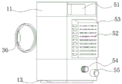
Referring to fig. 1, the utility model discloses a dryer for clothing processing, which comprises a cabinet body 1, a roller 2, a door body 3, a dust collecting box 4 and a working assembly 5, wherein the roller 2 is fixedly connected inside the cabinet body 1, one side of the cabinet body 1 is fixedly connected with one side of the door body 3, the dust collecting box 4 is arranged on one side of the cabinet body 1, the dust collecting box 4 is movably connected with the cabinet body 1, the dust collecting box 4 is positioned below the roller 2, one side of the cabinet body 1 is fixedly connected with one side of the working assembly 5, the cabinet body 1 consists of a shell 11, a control screen 12 and a supporting plate 13, one side of the shell 11 is provided with the control screen 12, and the bottom of the shell 11 is fixedly connected with one side of the supporting plate 13.
In the above arrangement, the drum 2 is located inside the cabinet 1, the drum 2 can hold clothes, the door 3 can be used to close the drum 2, hot air in the drum 2 is prevented from flowing out, the dust collecting box 4 can collect fluff on the surface layer of the clothes, and the drum 2 can dry the clothes under the action of the working assembly 5.
As shown in fig. 2 and 3, the drum 2 is composed of a drum 21, a vent hole 22 and an auger shaft 23, the vent hole 22 is arranged on the side surface of the drum 21, the auger shaft 23 is uniformly distributed inside the drum 21, the door body 3 is composed of a fixed block 31, a fixed shaft 32, a connecting block 33, a door frame 34, an observation window 35 and a door handle 36, two ends of the fixed shaft 32 are fixedly connected with two side surfaces of the fixed block 31, the connecting block 33 penetrates through the fixed shaft 32 and the fixed shaft 32 to be movably connected, one side surface of the door frame 34 is fixedly connected with one side surface of the connecting block 33, the periphery of the observation window 35 is fixedly connected with the inside of the door frame 34, and one side surface of the door frame 34 is fixedly connected with one side surface of the door handle 36.
In the above arrangement, the door handle 36 opens the door body 3 to place clothes inside the drum 2, after the placement is completed, the door body 3 can close the drum 2 when the drum 2 is operated, the auger shaft 23 in the drum 2 can separate the clothes, the clothes can be prevented from being wound together when the drum 2 rotates, and the air flow in the drum 2 can drive the fluff on the surface layer of the clothes to enter the dust collecting box 4 through the air vent 22.
As shown in fig. 4 and 5, the dust collecting box 4 is composed of a box body 41, a filter screen 42 and a handle 43, wherein the filter screen 42 is movably connected to the upper side of the box body 41, the handle 43 is fixedly connected to one side of the box body 41, the working assembly 5 is composed of a heater 51, a fan 52, a protection cover 53, a motor 54 and an air outlet 55, one side of the heater 51 is fixedly connected to the upper side of the cabinet body 1, one side of the fan 52 is fixedly connected to one side of the cabinet body 1, one side of the protection cover 53 is fixedly connected to one side of the cabinet body 1, the fan 52 is located in the protection cover 53, one side of the motor 54 is fixedly connected to one side of the cabinet body 1, and one side of the air outlet 55 is fixedly connected to one side of the cabinet body 1.
In the above arrangement, some small fluff will enter the box 41 through the filter screen 42, larger fluff is collected by the filter screen 42, the box 41 is taken out by the handle 43 after drying is completed, the fluff collected by the dust collecting box 4 is processed, the heater 51 will heat the air in the drum 2 when the dryer is in operation, the motor 54 drives the drum 2 to rotate, the fan 52 rotates to bring the air flow into the interior of the drum 2 for removing the air flow from the clothes under the action of the motor 54, and the fan 52 is prevented from damaging the human body when rotating by the protective cover 53, and a part of the air flow flows out through the air outlet 55 when the fan 52 brings the hot air flow into the drum 2.
One specific application of this embodiment is: when in use, the door body 3 is opened through the door handle 36, clothes are placed in the roller 2, after the clothes are placed, the door body 3 is closed, the roller 2 can be sealed by the door body 3, the drying temperature and time can be set on the control screen 12, the power dryer is started to start working, the internal condition can be observed through the observation window 35, the roller 2 can rotate under the drive of the motor 54, the auger shaft 23 in the roller 2 can separate the clothes, the clothes are prevented from being wound together when the roller 2 rotates, the fan 52 rotates to bring the clothes in the roller 2 to flow air under the action of the motor 54, and a part of air flows out through the air outlet 55 when the fan 52 brings the hot air into the roller 2, in this way, circulating air flow is formed in the roller 2, the heater 51 works to heat air in the roller 2, the motor 54 can drive the roller 2 to perform forward and reverse rotation constant speed motion in the drying process, clothes can be fully contacted with hot air in the drying process, drying efficiency of the clothes is accelerated, under the driving of the air flow in the roller 2 when the roller 2 rotates, fluff on the clothes can be collected by the dust collecting box 4 through the air vent 22, some smaller fluff can enter the box body 41 through the filter screen 42, larger fluff is collected by the filter screen 42, after the clothes are dried, the door body 3 is opened through the door handle 36, the clothes in the roller 2 are taken out, the box body 41 is taken out through the handle 43, and the fluff collected by the dust collecting box 4 is processed.
The foregoing is only a preferred embodiment of the present utility model, and the present utility model is not limited thereto, and any modification, equivalent replacement, and improvement of some of the technical features described in the foregoing embodiments are all within the scope of the present utility model.
Claims (6)
1. The utility model provides a dryer for clothing processing, includes cabinet body (1), cylinder (2), door body (3), dust collection box (4) and work subassembly (5), its characterized in that: the novel dust collector is characterized in that the roller (2) is fixedly connected to the inside of the cabinet body (1), one side face of the cabinet body (1) is fixedly connected with one side face of the door body (3), one side face of the cabinet body (1) is provided with the dust collecting box (4), the dust collecting box (4) is movably connected with the cabinet body (1), the dust collecting box (4) is located below the roller (2), and one side face of the cabinet body (1) is fixedly connected with one side face of the working assembly (5).
2. A dryer for clothing processing as claimed in claim 1, wherein: the cabinet body (1) is composed of a shell (11), a control screen (12) and a supporting plate (13), wherein the control screen (12) is arranged on one side face of the shell (11), and the bottom of the shell (11) is fixedly connected with one side face of the supporting plate (13).
3. A dryer for clothing processing as claimed in claim 1, wherein: the roller (2) is composed of a cylinder body (21), an air vent (22) and an auger shaft (23), wherein the air vent (22) is arranged on the side face of the cylinder body (21), and the auger shaft (23) is uniformly distributed in the cylinder body (21).
4. A dryer for clothing processing as claimed in claim 1, wherein: the door body (3) is formed by a fixed block (31), a fixed shaft (32), a connecting block (33), a door frame (34), an observation window (35) and a door handle (36), wherein two ends of the fixed shaft (32) are fixedly connected with two side surfaces of the fixed block (31), the connecting block (33) penetrates through the fixed shaft (32) and is movably connected between the fixed shaft (32), one side surface of the door frame (34) is fixedly connected with one side surface of the connecting block (33), the periphery of the observation window (35) is fixedly connected with the inside of the door frame (34), and one side surface of the door frame (34) is fixedly connected with one side surface of the door handle (36).
5. A dryer for clothing processing as claimed in claim 1, wherein: the dust box (4) is composed of a box body (41), a filter screen (42) and a handle (43), wherein the filter screen (42) is movably connected above the box body (41), and one side surface of the box body (41) is fixedly connected with the handle (43).
6. A dryer for clothing processing as claimed in claim 1, wherein: working assembly (5) comprises heater (51), fan (52), protection casing (53), motor (54) and air outlet (55) jointly, a side fixed connection of heater (51) in the top of cabinet body (1), a side fixed connection of fan (52) in a side of cabinet body (1), a side fixed connection of protection casing (53) in a side of cabinet body (1), fan (52) are located the inside of protection casing (53), a side fixed connection of motor (54) in a side of cabinet body (1), a side fixed connection of air outlet (55) in a side of cabinet body (1).
Priority Applications (1)
| Application Number | Priority Date | Filing Date | Title |
|---|---|---|---|
| CN202222656372.2U CN218932655U (en) | 2022-10-10 | 2022-10-10 | Dryer for clothing processing |
Applications Claiming Priority (1)
| Application Number | Priority Date | Filing Date | Title |
|---|---|---|---|
| CN202222656372.2U CN218932655U (en) | 2022-10-10 | 2022-10-10 | Dryer for clothing processing |
Publications (1)
| Publication Number | Publication Date |
|---|---|
| CN218932655U true CN218932655U (en) | 2023-04-28 |
Family
ID=86061948
Family Applications (1)
| Application Number | Title | Priority Date | Filing Date |
|---|---|---|---|
| CN202222656372.2U Active CN218932655U (en) | 2022-10-10 | 2022-10-10 | Dryer for clothing processing |
Country Status (1)
| Country | Link |
|---|---|
| CN (1) | CN218932655U (en) |
-
2022
- 2022-10-10 CN CN202222656372.2U patent/CN218932655U/en active Active
Similar Documents
| Publication | Publication Date | Title |
|---|---|---|
| CN218932655U (en) | Dryer for clothing processing | |
| KR101241915B1 (en) | drying device | |
| CN212611367U (en) | Efficient cloth printing device | |
| CN211006051U (en) | Drying machine | |
| CN213114004U (en) | 100Kg heat pump type internal circulation dryer | |
| CN113389002A (en) | Clothes treating appliance | |
| CN207582130U (en) | A kind of washing facility | |
| JP4013622B2 (en) | Washing and drying machine | |
| KR101191208B1 (en) | drying device | |
| CN219862013U (en) | Drying device | |
| CN112030493B (en) | 100Kg heat pump type internal circulation dryer | |
| CN218115849U (en) | Fabrics removes wrinkle drying device | |
| KR100504459B1 (en) | Drying Equipment of Drum Washing Machine | |
| CN220326748U (en) | Oven for processing vegetables | |
| WO2022199640A1 (en) | Integrated washing and drying device | |
| CN213578660U (en) | Drying-machine is used in secondary element fertilizer processing with heat recovery | |
| CN220288053U (en) | Textile fabric air-drying device for spinning | |
| KR101685977B1 (en) | drying device | |
| KR0131285Y1 (en) | A washing machine with a drying function | |
| CN215251695U (en) | Cloth washing equipment based on textile production | |
| CN214116008U (en) | Clothes dryer | |
| CN214950364U (en) | Efficient drying device for sweater processing | |
| CN220643510U (en) | Textile dewatering equipment for textile processing | |
| CN214172816U (en) | Drying box for garment processing | |
| CN215571914U (en) | Weaving cloth drying device |
Legal Events
| Date | Code | Title | Description |
|---|---|---|---|
| GR01 | Patent grant | ||
| GR01 | Patent grant |