CN218920341U - New forms of energy photovoltaic electroplax mounting structure convenient to dismouting - Google Patents
New forms of energy photovoltaic electroplax mounting structure convenient to dismouting Download PDFInfo
- Publication number
- CN218920341U CN218920341U CN202320147407.1U CN202320147407U CN218920341U CN 218920341 U CN218920341 U CN 218920341U CN 202320147407 U CN202320147407 U CN 202320147407U CN 218920341 U CN218920341 U CN 218920341U
- Authority
- CN
- China
- Prior art keywords
- wall
- mounting
- energy photovoltaic
- support frame
- photovoltaic panel
- Prior art date
- Legal status (The legal status is an assumption and is not a legal conclusion. Google has not performed a legal analysis and makes no representation as to the accuracy of the status listed.)
- Active
Links
Images


Classifications
-
- Y—GENERAL TAGGING OF NEW TECHNOLOGICAL DEVELOPMENTS; GENERAL TAGGING OF CROSS-SECTIONAL TECHNOLOGIES SPANNING OVER SEVERAL SECTIONS OF THE IPC; TECHNICAL SUBJECTS COVERED BY FORMER USPC CROSS-REFERENCE ART COLLECTIONS [XRACs] AND DIGESTS
- Y02—TECHNOLOGIES OR APPLICATIONS FOR MITIGATION OR ADAPTATION AGAINST CLIMATE CHANGE
- Y02E—REDUCTION OF GREENHOUSE GAS [GHG] EMISSIONS, RELATED TO ENERGY GENERATION, TRANSMISSION OR DISTRIBUTION
- Y02E10/00—Energy generation through renewable energy sources
- Y02E10/50—Photovoltaic [PV] energy
Abstract
The utility model discloses a new energy photovoltaic panel mounting structure convenient to disassemble and assemble, which comprises: the first support frame, the second support frame is installed at the top of first support frame, the link, the inner wall of first support frame runs through and installs the link. According to the novel energy photovoltaic panel mounting structure, the mounting frame and the fixing frame are arranged, so that the mounting stability of the novel energy photovoltaic panel can be improved while the mounting of the novel energy photovoltaic panel is more convenient, the second support frame is fixedly connected with the mounting frame through the connecting holes, the mounting plate and the mounting holes, the fixing frame is fixedly arranged on the inner wall of the mounting groove through the fixing holes and the mounting screws, the novel energy photovoltaic panel is arranged on the inner wall of the fixing groove, the two ends of the novel energy photovoltaic panel are clamped into the clamping groove, and the springs are used for fixing the novel energy photovoltaic panel by pushing the fixing blocks, so that the stability of the novel energy photovoltaic panel is improved while the novel energy photovoltaic panel is more convenient to assemble and disassemble, and the stability of the novel energy photovoltaic panel can be guaranteed by the mounting structure under severe weather conditions.
Description
Technical Field
The utility model relates to the technical field of new energy photovoltaic electric plates, in particular to a new energy photovoltaic electric plate mounting structure convenient to assemble and disassemble.
Background
The photovoltaic panel assembly is a power generation device capable of generating direct current when exposed to sunlight, and is composed of thin solid photovoltaic cells which are almost entirely made of semiconductor materials. Because of no movable part, the photovoltaic module can be operated for a long time without causing any loss, and the photovoltaic module is mainly made of high-efficiency monocrystalline silicon or polycrystalline silicon photovoltaic cells, high-transmittance toughened glass, corrosion-resistant aluminum, multiple frames and other materials, and is manufactured by using an advanced vacuum lamination process and a pulse welding process, and the installation of the new energy photovoltaic panel needs to be applied to a new energy photovoltaic panel installation structure.
The existing installation structure is used for installing and fixing the new energy photovoltaic electric plate by adopting the fixing piece and the fixing bolt, but the installation process of the traditional new energy photovoltaic electric plate is complex, and the installation process is used for installing the new energy photovoltaic electric plate by adopting the angle fixing installation, so that the installation of the new energy photovoltaic electric plate has the problems of low installation efficiency and poor installation stability.
Disclosure of Invention
The utility model aims to provide a new energy photovoltaic panel mounting structure convenient to assemble and disassemble, so as to solve the technical problems of low mounting efficiency and poor mounting stability in the conventional new energy photovoltaic panel mounting process in the background technology.
In order to achieve the above purpose, the present utility model provides the following technical solutions: new forms of energy photovoltaic electroplax mounting structure convenient to dismouting includes:
the top of the first support frame is provided with a second support frame;
the connecting frame is arranged on the inner wall of the first supporting frame in a penetrating way;
the mounting bracket is installed at the top of second support frame, the multiunit mounting panel is installed to the outer wall of mounting bracket, the inner wall of mounting panel runs through and is equipped with the mounting hole, install the mounting screw is run through to the outside of mounting bracket, the inner wall of mounting bracket runs through and is equipped with the mounting groove, the inner wall of mounting groove runs through and installs the mount, the handle is installed to the outer wall of mount, the inner wall of mount runs through and is equipped with two sets of fixed orificess, the inner wall of mount runs through and is equipped with the fixed slot, and multiunit spring is all installed to the inner wall both sides of fixed slot, the fixed block is installed on the top of spring, the inner wall of fixed block runs through and is equipped with the draw-in groove.
Preferably, the bottom of the first support frame is provided with a fixed plate, and the inner wall of the fixed plate is provided with two groups of holes in a penetrating way.
Preferably, the inner wall of the second support frame is provided with two groups of connecting holes in a penetrating way, the bottom of the second support frame is provided with two groups of connecting ends, and the top end of the first support frame is provided with the inner wall of the connecting ends in a penetrating way.
Preferably, the inner wall of the first support frame is provided with a groove body in a penetrating mode.
Preferably, a limiting block is arranged on the inner wall of the groove body.
Preferably, the outer wall of the first support frame is provided with a fixing bolt in a penetrating way.
Preferably, the inner wall of the connecting frame is provided with a plurality of groups of connecting grooves in a penetrating mode, and the top end of the connecting frame is provided with a limiting plate.
Compared with the prior art, the utility model has the beneficial effects that:
1. according to the novel energy photovoltaic panel mounting structure, the mounting frame and the fixing frame are arranged, so that the mounting of the novel energy photovoltaic panel can be more convenient, the mounting stability of the novel energy photovoltaic panel is improved, the second support frame is fixedly connected with the mounting frame through the connecting holes, the mounting plate and the mounting holes, the fixing frame is fixedly arranged on the inner wall of the mounting groove through the fixing holes and the mounting screws, the fixing frame is conveniently pulled out of the inner wall of the mounting groove by the aid of the handle, the novel energy photovoltaic panel is arranged on the inner wall of the fixing groove, two ends of the novel energy photovoltaic panel are clamped into the clamping groove, and the novel energy photovoltaic panel is fixed by the springs through pushing the fixing blocks, so that the mounting stability of the novel energy photovoltaic panel is improved while the novel energy photovoltaic panel is more convenient to mount and dismount, and the mounting structure can also ensure the mounting stability of the novel energy photovoltaic panel under severe weather conditions, and the novel energy photovoltaic panel mounting structure is further applied more favorably;
2. according to the utility model, the height and the angle of the new energy photovoltaic panel mounting structure can be adjusted by installing the connecting frame, the connecting frame is fixedly installed on the inner wall of the tank body through the connecting grooves and the fixing bolts, and the plurality of groups of connecting grooves are arranged, so that an installer can adjust the position of the connecting frame on the inner wall of the tank body by installing the fixing bolts on different connecting grooves, the height of the first support frame can be adjusted, the supporting angle of the mounting structure can be adjusted by adjusting the height of the first support frame at one end, and thus the mounting structure can adjust the mounting height and the mounting angle of the new energy photovoltaic panel through different mounting requirements, further the application of the new energy photovoltaic panel mounting structure is facilitated, the mounting structure can be used for a second time, the waste of materials is reduced, and the mounting of the limiting block and the limiting plate is used for limiting the connecting frame.
Drawings
FIG. 1 is a schematic diagram of the overall structure of the present utility model;
FIG. 2 is a schematic view of a first support frame according to the present utility model;
FIG. 3 is a schematic view of a mounting frame according to the present utility model;
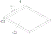
FIG. 4 is a schematic view of a fixing frame according to the present utility model;
FIG. 5 is a schematic view of a spring structure according to the present utility model;
FIG. 6 is a schematic view of a fixed block structure according to the present utility model;
fig. 7 is a schematic view of a structure of a connecting frame according to the present utility model.
In the figure: 1. a first support frame; 101. a fixing plate; 102. a hole; 2. a second support frame; 201. a connection hole; 202. a connection end; 3. a mounting frame; 301. a mounting plate; 302. a mounting hole; 303. installing a screw; 304. a mounting groove; 4. a fixing frame; 401. a handle; 402. a fixing hole; 403. a fixing groove; 404. a spring; 5. a fixed block; 501. a clamping groove; 6. a connecting frame; 601. a connecting groove; 602. a limiting plate; 7. a tank body; 701. a limiting block; 702. and (5) fixing bolts.
Detailed Description
The following description of the embodiments of the present utility model will be made clearly and completely with reference to the accompanying drawings, in which it is apparent that the embodiments described are only some embodiments of the present utility model, but not all embodiments. All other embodiments, which can be made by those skilled in the art based on the embodiments of the utility model without making any inventive effort, are intended to be within the scope of the utility model.
In the description of the present utility model, it should be noted that the directions or positional relationships indicated by the terms "upper", "lower", "inner", "outer", "front", "rear", "both ends", "one end", "the other end", etc. are based on the directions or positional relationships shown in the drawings, are merely for convenience of describing the present utility model and simplifying the description, and do not indicate or imply that the devices or elements referred to must have a specific direction, be configured and operated in the specific direction, and thus should not be construed as limiting the present utility model. Furthermore, the terms "first," "second," and the like, are used for descriptive purposes only and are not to be construed as indicating or implying relative importance.
In the description of the present utility model, it should be noted that, unless explicitly specified and limited otherwise, the terms "mounted," "provided," "connected," and the like are to be construed broadly, and may be fixedly connected, detachably connected, or integrally connected, for example; can be mechanically or electrically connected; can be directly connected or indirectly connected through an intermediate medium, and can be communication between two elements. The specific meaning of the above terms in the present utility model will be understood in specific cases by those of ordinary skill in the art.
Referring to fig. 1 and 2, a new energy photovoltaic panel installation structure convenient to disassemble and assemble includes: the first support frame 1, second support frame 2 is installed at the top of first support frame 1, link 6 is installed in the inner wall penetration of first support frame 1, fixed plate 101 is installed to the bottom of first support frame 1, the inner wall penetration of fixed plate 101 is equipped with two sets of holes 102, the inner wall penetration of second support frame 2 is equipped with two sets of connecting holes 201, two sets of link 202 are installed to the bottom of second support frame 2, and install in the inner wall of link 202 in the top penetration of first support frame 1, mounting structure is new forms for new forms photovoltaic panel mounting structure, mounting structure comprises first support frame 1 respectively, second support frame 2, fixed plate 101 and mounting bracket 3, first support frame 1 and second support frame 2 are used for providing the supporting role for new forms photovoltaic panel, first support frame 1 and second support frame 2 carry out fixed mounting through fixed plate 101 and hole 102 and ground, first support frame 1 is connected through link 202 and second support frame 2.
Please refer to fig. 1 and 3 and fig. 4 and fig. 5 and fig. 6, mounting bracket 3 is installed at the top of second support frame 2, multiunit mounting panel 301 is installed to the outer wall of mounting bracket 3, the inner wall of mounting bracket 301 runs through and is equipped with mounting hole 302, mounting screw 303 is installed in the outside run-through of mounting bracket 3, the inner wall of mounting bracket 3 runs through and is equipped with mounting groove 304, mount 4 is installed to the outer wall of mount 4, the inner wall of mount 4 runs through and is equipped with two sets of fixed orifices 402, the inner wall of mount 4 runs through and is equipped with fixed slot 403, multiunit spring 404 is all installed to the inner wall both sides of fixed slot 403, fixed block 5 is installed on the top of spring 404, the inner wall of fixed block 5 runs through and is equipped with draw-in groove 501, second support frame 2 is connected fixedly through connecting hole 201, mounting plate 301 and mounting hole 302 and mounting screw 303 fixed mounting groove 304's inner wall, the installation of handle 401 is used for conveniently taking out mount 4 from mounting groove 304's inner wall, new energy photovoltaic panel installs in the inner wall of fixed slot 403, it will block into draw-in the draw-in groove in the inner wall, the fixed plate 5, the new energy photovoltaic panel is installed through the fixed plate is installed to the new energy photovoltaic panel of spring 5, and photovoltaic panel's new energy photovoltaic panel's stability is improved simultaneously, and photovoltaic stability is improved.
Referring to fig. 2 and 7, the inner wall of the first support frame 1 is provided with a groove body 7 in a penetrating manner, the inner wall of the groove body 7 is provided with a limiting block 701, the outer wall of the first support frame 1 is provided with a fixing bolt 702 in a penetrating manner, the inner wall of the connecting frame 6 is provided with a plurality of groups of connecting grooves 601 in a penetrating manner, the top end of the connecting frame 6 is provided with a limiting plate 602, the connecting frame 6 is fixedly arranged on the inner wall of the groove body 7 through the connecting grooves 601 and the fixing bolt 702, the plurality of groups of connecting grooves 601 are arranged, an installer can adjust the position of the connecting frame 6 on the inner wall of the groove body 7 through installing the fixing bolts 702 to different connecting grooves 601, and therefore, the height of the first support frame 1 at one end can be adjusted, the supporting angle of the installation structure can be adjusted through the adjustment of the difference of installation requirements, the installation height and the installation angle of the new energy photovoltaic panel can be adjusted, the installation structure can be used for secondary use, the material waste is reduced, and the installation of the limiting block 701 and the limiting plate 602 is used for limiting the connecting frame 6.
The working principle is that the installation structure is a new energy photovoltaic panel installation structure, the installation structure is respectively composed of a first support frame 1, a second support frame 2, a fixing plate 101 and an installation frame 3, the first support frame 1 and the second support frame 2 are used for providing supporting functions for the new energy photovoltaic panel, the first support frame 1 and the second support frame 2 are fixedly installed with the ground through the fixing plate 101 and a hole 102, the first support frame 1 is connected with the second support frame 2 through a connecting end 202, the second support frame 2 is fixedly connected with the installation frame 3 through a connecting hole 201, an installation plate 301 and an installation hole 302, the installation of a fixing frame 4 is fixedly installed on the inner wall of an installation groove 304 through a fixing hole 402 and an installation screw 303, the installation of a handle 401 is used for conveniently drawing the fixing frame 4 out from the inner wall of the installation groove 304, the new energy photovoltaic panel is installed on the inner wall of the fixing groove 403, two ends of the new energy photovoltaic panel are clamped into the clamping groove 501, the spring 404 fixes the new energy photovoltaic panel by pushing the fixing block 5, so that the mounting stability of the new energy photovoltaic panel is improved while the new energy photovoltaic panel is more convenient to mount and dismount, the mounting structure can ensure the mounting stability of the new energy photovoltaic panel under severe weather environment, the application of the new energy photovoltaic panel mounting structure is further facilitated, the connecting frame 6 is fixedly mounted on the inner wall of the groove body 7 through the connecting groove 601 and the fixing bolt 702, the plurality of groups of connecting grooves 601 are arranged, the installer can adjust the positions of the connecting frame 6 on the inner wall of the groove body 7 by mounting the fixing bolts 702 on different connecting grooves 601, the height of the first supporting frame 1 can be adjusted, the supporting angle of the mounting structure can be adjusted by adjusting the height of the first supporting frame 1 at one end, the mounting structure can be mounted through the difference of mounting requirements, the installation height and the installation angle of the new energy photovoltaic electric plate are adjusted, and therefore the application of the new energy photovoltaic electric plate installation structure is facilitated, the installation structure can be used for a second time, the waste of materials is reduced, and the installation of the limiting block 701 and the limiting plate 602 is used for limiting the connecting frame 6.
It will be evident to those skilled in the art that the utility model is not limited to the details of the foregoing illustrative embodiments, and that the present utility model may be embodied in other specific forms without departing from the spirit or essential characteristics thereof. The present embodiments are, therefore, to be considered in all respects as illustrative and not restrictive, the scope of the utility model being indicated by the appended claims rather than by the foregoing description, and all changes which come within the meaning and range of equivalency of the claims are therefore intended to be embraced therein. Any reference sign in a claim should not be construed as limiting the claim concerned.
Claims (7)
1. New forms of energy photovoltaic electroplax mounting structure convenient to dismouting, its characterized in that includes:
the device comprises a first support frame (1), wherein a second support frame (2) is arranged at the top of the first support frame (1);
the connecting frame (6) is arranged on the inner wall of the first supporting frame (1) in a penetrating way;
the mounting bracket (3) is installed at the top of second support frame (2), multiunit mounting panel (301) are installed to the outer wall of mounting bracket (3), the inner wall of mounting panel (301) runs through and is equipped with mounting hole (302), the outside of mounting bracket (3) runs through and installs mounting screw (303), the inner wall of mounting bracket (3) runs through and is equipped with mounting groove (304), the inner wall of mounting groove (304) runs through and installs mount (4), handle (401) are installed to the outer wall of mount (4), the inner wall of mount (4) runs through and is equipped with two sets of fixed orifices (402), the inner wall of mount (4) runs through and is equipped with fixed slot (403), multiunit spring (404) are all installed to the inner wall both sides of fixed slot (403), fixed block (5) are installed on the top of spring (404), the inner wall of fixed block (5) runs through and is equipped with draw-in groove (501).
2. The new energy photovoltaic panel mounting structure convenient to disassemble and assemble according to claim 1, wherein: the bottom of the first support frame (1) is provided with a fixing plate (101), and two groups of holes (102) are formed in the inner wall of the fixing plate (101) in a penetrating mode.
3. The new energy photovoltaic panel mounting structure convenient to disassemble and assemble according to claim 1, wherein: the inner wall of second support frame (2) runs through and is equipped with two sets of connecting holes (201), and two sets of link (202) are installed to the bottom of second support frame (2), and the top of first support frame (1) runs through and installs in the inner wall of link (202).
4. The new energy photovoltaic panel mounting structure convenient to disassemble and assemble according to claim 1, wherein: the inner wall of the first support frame (1) is provided with a groove body (7) in a penetrating way.
5. The new energy photovoltaic panel mounting structure convenient to disassemble and assemble according to claim 4, wherein: a limiting block (701) is arranged on the inner wall of the groove body (7).
6. The new energy photovoltaic panel mounting structure convenient to disassemble and assemble according to claim 1, wherein: the outer wall of the first support frame (1) is provided with a fixing bolt (702) in a penetrating mode.
7. The new energy photovoltaic panel mounting structure convenient to disassemble and assemble according to claim 1, wherein: the inner wall of link (6) runs through and is equipped with multiunit spread groove (601), and limiting plate (602) are installed on the top of link (6).
Priority Applications (1)
| Application Number | Priority Date | Filing Date | Title |
|---|---|---|---|
| CN202320147407.1U CN218920341U (en) | 2023-02-08 | 2023-02-08 | New forms of energy photovoltaic electroplax mounting structure convenient to dismouting |
Applications Claiming Priority (1)
| Application Number | Priority Date | Filing Date | Title |
|---|---|---|---|
| CN202320147407.1U CN218920341U (en) | 2023-02-08 | 2023-02-08 | New forms of energy photovoltaic electroplax mounting structure convenient to dismouting |
Publications (1)
| Publication Number | Publication Date |
|---|---|
| CN218920341U true CN218920341U (en) | 2023-04-25 |
Family
ID=86045008
Family Applications (1)
| Application Number | Title | Priority Date | Filing Date |
|---|---|---|---|
| CN202320147407.1U Active CN218920341U (en) | 2023-02-08 | 2023-02-08 | New forms of energy photovoltaic electroplax mounting structure convenient to dismouting |
Country Status (1)
| Country | Link |
|---|---|
| CN (1) | CN218920341U (en) |
-
2023
- 2023-02-08 CN CN202320147407.1U patent/CN218920341U/en active Active
Similar Documents
| Publication | Publication Date | Title |
|---|---|---|
| CN218920341U (en) | New forms of energy photovoltaic electroplax mounting structure convenient to dismouting | |
| CN110829971B (en) | Supporting device for photovoltaic solar energy | |
| CN210120515U (en) | Installation device convenient to installation photovoltaic board | |
| CN209805736U (en) | Outdoor sun-curing plate support for crystalline silicon solar photovoltaic module | |
| CN112838813A (en) | Mounting rack of photovoltaic power generation panel and mounting method thereof | |
| CN219592334U (en) | Photovoltaic plate structure convenient to adjust | |
| CN218771948U (en) | Photovoltaic solar panel convenient to installation | |
| CN220307151U (en) | Photovoltaic board supporting member convenient to roof installation | |
| CN219164490U (en) | Photovoltaic panel installation component | |
| CN213305321U (en) | Adjustable support that photovoltaic power generation used | |
| CN216490333U (en) | A solar cell panel fixing device for new forms of energy electricity generation | |
| CN216698403U (en) | Photovoltaic cell board processing shaping device | |
| CN219247749U (en) | Wall body mount of photovoltaic board | |
| CN217545963U (en) | Household movable solar photovoltaic power generation device | |
| CN210431299U (en) | Solar panel mounting bracket | |
| CN220190810U (en) | Single crystal single glass TOPCon assembly | |
| CN212562222U (en) | Roof photovoltaic support of various steel tile is exempted from to destroy in sucking disc formula installation | |
| CN219718143U (en) | Adjusting component for photovoltaic panel installation | |
| CN220359107U (en) | Solar photovoltaic device | |
| CN213817636U (en) | Photovoltaic power generation device with easy mounting structure of subassembly | |
| CN220527966U (en) | Adjusting mechanism for photovoltaic module | |
| CN217445310U (en) | Polycrystal solar energy component with connection structure | |
| CN215934792U (en) | Wall photovoltaic module | |
| CN217159601U (en) | Mounting bracket with strong adaptability for photovoltaic power generation | |
| CN112187146B (en) | Solar energy component's connection mounting structure |
Legal Events
| Date | Code | Title | Description |
|---|---|---|---|
| GR01 | Patent grant | ||
| GR01 | Patent grant |