CN218891092U - Improved integral stamping die ejector block - Google Patents
Improved integral stamping die ejector block Download PDFInfo
- Publication number
- CN218891092U CN218891092U CN202223122813.7U CN202223122813U CN218891092U CN 218891092 U CN218891092 U CN 218891092U CN 202223122813 U CN202223122813 U CN 202223122813U CN 218891092 U CN218891092 U CN 218891092U
- Authority
- CN
- China
- Prior art keywords
- block
- stamping die
- jig
- improved
- chamfer
- Prior art date
- Legal status (The legal status is an assumption and is not a legal conclusion. Google has not performed a legal analysis and makes no representation as to the accuracy of the status listed.)
- Active
Links
- 238000003825 pressing Methods 0.000 claims description 14
- 238000000034 method Methods 0.000 abstract description 3
- 238000009434 installation Methods 0.000 abstract description 2
- 238000003754 machining Methods 0.000 description 4
- 230000003139 buffering effect Effects 0.000 description 2
- 230000000694 effects Effects 0.000 description 2
- 238000012986 modification Methods 0.000 description 2
- 230000004048 modification Effects 0.000 description 2
- 230000009286 beneficial effect Effects 0.000 description 1
- 230000007547 defect Effects 0.000 description 1
- 238000009776 industrial production Methods 0.000 description 1
- 239000000463 material Substances 0.000 description 1
- 238000003672 processing method Methods 0.000 description 1
- 239000011265 semifinished product Substances 0.000 description 1
Images


Classifications
-
- Y—GENERAL TAGGING OF NEW TECHNOLOGICAL DEVELOPMENTS; GENERAL TAGGING OF CROSS-SECTIONAL TECHNOLOGIES SPANNING OVER SEVERAL SECTIONS OF THE IPC; TECHNICAL SUBJECTS COVERED BY FORMER USPC CROSS-REFERENCE ART COLLECTIONS [XRACs] AND DIGESTS
- Y02—TECHNOLOGIES OR APPLICATIONS FOR MITIGATION OR ADAPTATION AGAINST CLIMATE CHANGE
- Y02E—REDUCTION OF GREENHOUSE GAS [GHG] EMISSIONS, RELATED TO ENERGY GENERATION, TRANSMISSION OR DISTRIBUTION
- Y02E60/00—Enabling technologies; Technologies with a potential or indirect contribution to GHG emissions mitigation
- Y02E60/10—Energy storage using batteries
Landscapes
- Forging (AREA)
Abstract
The utility model relates to the field of stamping dies and discloses an improved integrated stamping die ejector block which comprises a jig, wherein a plurality of punches are clamped on the inner front end surface of the jig, first clamping grooves are formed in the top ends of the plurality of punches, an ejector pin block is arranged on the top end of the jig, and second clamping grooves are formed in the inner bottom ends of the ejector pin block, which are positioned on the top ends of the plurality of first clamping grooves. According to the utility model, the part of the stamping die is large in batch, because of the complex shape and the thinner front end part (0.2-0.5), the phenomenon of unstable processing precision is easy to occur when the workpiece is clamped, the complex and tiny stamping die is used for designing an integrated top block according to the cavity data and the step pitch of the complex and tiny stamping die to perform operation, the installation is time-saving, the fitting degree of the top block and the workpiece is high, the processing process is firm, the processing precision is improved, the workpiece clamping time is greatly shortened after the top block is improved, the improved top block can be better fitted with the workpiece, and the stability of the processing precision is improved.
Description
Technical Field
The utility model relates to the field of stamping dies, in particular to an improved integral type stamping die ejector block.
Background
The stamping die is a die commonly used in industrial production, and in the use process of the stamping die, usually in cold stamping processing, a material or a part to be processed is separated or plastically deformed, and is processed into a semi-finished product or a finished part, so that a pressure processing method of the required part is obtained.
The part of the large-batch punch accessories of the stamping die is complex in shape and the front end part of the part is thinner (between 0.2 and 0.5), so that the workpiece is difficult and time-consuming to clamp, and the phenomenon of unstable processing precision is very easy to occur.
Disclosure of Invention
The utility model aims to solve the defects in the prior art, and provides an improved integral stamping die ejector block, which greatly shortens the workpiece clamping time after being improved, can better fit with a workpiece and improves the stability of processing precision.
In order to achieve the above purpose, the present utility model provides the following technical solutions:
the utility model provides an improvement formula integral type stamping die kicking block, includes the tool, the terminal surface joint has a plurality of punches in the tool, and a plurality of first joint groove has all been seted up on punch top, the tool top is provided with the thimble piece, the second joint groove has all been seted up on thimble piece inner bottom end position a plurality of first joint groove tops;
the fixture comprises a fixture, a fixture and a fixing stud, wherein a first chamfer is formed in one side of the front end face of the fixture, three thread grooves are formed in the position, located at the first chamfer, of the fixture, a pressing block is arranged at the position, located at the first chamfer, of the fixture, through grooves are formed in the pressing block, and one thread groove is internally connected with the fixing stud in a threaded manner;
through the technical scheme, when the jig is used, the plurality of punches are clamped in the clamping grooves of the jig, the thimble block is covered, and then the pressing block is fixed to a proper position through the cooperation of the fixing studs and the thread grooves.
Further, a gasket is arranged between the pressing block and the fixed stud;
through above-mentioned technical scheme, set up the gasket and played the effect of buffering.
Further, third chamfers are formed at four corners of the thimble block;
through above-mentioned technical scheme, set up the third chamfer in order to get rid of the burr that produces because of the machining on the part, also in order to be convenient for the part assembly.
Further, a second chamfer is formed on one side, far away from the first chamfer, of the front end face of the jig;
through above-mentioned technical scheme, set up the second chamfer in order to get rid of the burr that produces because of the machining on the part, also in order to be convenient for the part assembly.
Further, a fixing block is fixedly arranged on one side, close to the pressing block, of the front end face of the jig.
The utility model has the following beneficial effects:
1. according to the improved integral type stamping die ejector block provided by the utility model, the part of the stamping die is complex in shape and the front end part of the stamping die is thinner (between 0.2 and 0.5), so that the phenomenon of unstable processing precision is easily caused when a workpiece is clamped, the integral type ejector block is designed according to the cavity data and the step pitch of the complex and tiny stamping die assembly for operation, the installation time is saved, the matching degree of the ejector block and the workpiece is high, the processing process is firm, the processing precision is improved, the workpiece clamping time is greatly shortened after the ejector block is improved, the improved ejector block can better match with the workpiece, and the stability of the processing precision is improved.
Drawings
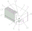
FIG. 1 is an isometric view of a thimble-removed portion of an ejector of an improved integrated stamping die according to the present utility model;
FIG. 2 is a front view of an improved integral stamping die top block according to the present utility model;
FIG. 3 is a bottom perspective view of a thimble of an improved integrated stamping die ejector;
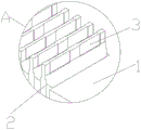
fig. 4 is a partial enlarged view of a in fig. 1.
Legend description:
1. a jig; 2. a punch; 3. a first clamping groove; 4. a thimble block; 5. a second clamping groove; 6. briquetting; 7. a fixed block; 8. a gasket; 9. fixing a stud; 10. a through groove; 11. a thread groove; 12. a first chamfer; 13. a second chamfer; 14. and (3) third chamfering.
Detailed Description
The following description of the embodiments of the present utility model will be made clearly and completely with reference to the accompanying drawings, in which it is apparent that the embodiments described are only some embodiments of the present utility model, but not all embodiments. All other embodiments, which can be made by those skilled in the art based on the embodiments of the utility model without making any inventive effort, are intended to be within the scope of the utility model.
Referring to fig. 1-4, one embodiment provided by the present utility model is: the utility model provides an improvement formula integral type stamping die kicking block, includes tool 1, and tool 1 interior front end joint has a plurality of punches 2, and first joint groove 3 has all been seted up on a plurality of punches 2 top, and tool 1 top is provided with thimble piece 4, and second joint groove 5 has all been seted up on thimble piece 4 inner bottom locates at a plurality of first joint groove 3 tops;
the jig comprises a jig 1, a jig, a pressing block 6, a fixing stud 9, a plurality of punches, a thimble block, a fixing stud and a clamping groove, wherein the first chamfer 12 is formed in one side of the front end face of the jig 1, three thread grooves 11 are formed in the position of the jig 1, located at the first chamfer 12, of the jig 1, the pressing block 6 is arranged in the position of the jig 1, through grooves 10 are formed in the pressing block 6, the fixing stud 9 is connected with the inner threads of one thread groove 11, when the jig is used, the plurality of punches are clamped in the clamping groove of the jig, the thimble block is covered, and then the pressing block is fixed to a proper position through the matching of the fixing stud and the thread grooves.
Be provided with gasket 8 between briquetting 6 and the fixed double-screw bolt 9, set up the gasket and played the effect of buffering, third chamfer 14 has all been seted up to thimble piece 4 four corners department, set up the third chamfer in order to get rid of the burr that produces because of the machining on the part, also in order to be convenient for the part assembly, second chamfer 13 has been seted up to one side that first chamfer 12 was kept away from to the terminal surface before the tool 1, set up the second chamfer in order to get rid of the burr that produces because of the machining on the part, also in order to be convenient for the part assembly, the tool 1 front end face is close to the fixed piece 7 that is provided with in one side of briquetting 6.
Working principle: when the jig is used, the plurality of punches 2 are clamped in the clamping grooves of the jig 1, the thimble blocks 4 are covered, and then the pressing blocks 6 are fixed at proper positions through the cooperation of the fixing studs 9 and the thread grooves 11.
Finally, it should be noted that: the foregoing description is only illustrative of the preferred embodiments of the present utility model, and although the present utility model has been described in detail with reference to the foregoing embodiments, it will be apparent to those skilled in the art that modifications may be made to the embodiments described, or equivalents may be substituted for elements thereof, and any modifications, equivalents, improvements or changes may be made without departing from the spirit and principles of the present utility model.
Claims (5)
1. An improvement formula integral type stamping die kicking block, includes tool (1), its characterized in that: the jig comprises a jig body, and is characterized in that a plurality of punches (2) are clamped on the inner front end face of the jig body (1), first clamping grooves (3) are formed in the top ends of the plurality of punches (2), ejector pin blocks (4) are arranged on the top ends of the jig body (1), and second clamping grooves (5) are formed in the inner bottom ends of the ejector pin blocks (4) located at the top ends of the plurality of first clamping grooves (3);
the jig comprises a jig body, and is characterized in that a first chamfer (12) is formed in one side of the front end face of the jig body (1), three thread grooves (11) are formed in the position, located at the first chamfer (12), of the jig body (1), a pressing block (6) is arranged at the position, located at the first chamfer (12), of the jig body, through grooves (10) are formed in the pressing block (6), and one of the through grooves (10) is connected with a fixing stud (9) through internal threads of the thread grooves (11).
2. The improved integral stamping die top block of claim 1, wherein: a gasket (8) is arranged between the pressing block (6) and the fixed stud (9).
3. The improved integral stamping die top block of claim 1, wherein: third chamfer angles (14) are formed in four corners of the thimble block (4).
4. The improved integral stamping die top block of claim 1, wherein: a second chamfer (13) is formed on one side, far away from the first chamfer (12), of the front end face of the jig (1).
5. The improved integral stamping die top block of claim 1, wherein: one side of the front end surface of the jig (1) close to the pressing block (6) is fixedly provided with a fixing block (7).
Priority Applications (1)
| Application Number | Priority Date | Filing Date | Title |
|---|---|---|---|
| CN202223122813.7U CN218891092U (en) | 2022-11-24 | 2022-11-24 | Improved integral stamping die ejector block |
Applications Claiming Priority (1)
| Application Number | Priority Date | Filing Date | Title |
|---|---|---|---|
| CN202223122813.7U CN218891092U (en) | 2022-11-24 | 2022-11-24 | Improved integral stamping die ejector block |
Publications (1)
| Publication Number | Publication Date |
|---|---|
| CN218891092U true CN218891092U (en) | 2023-04-21 |
Family
ID=86002913
Family Applications (1)
| Application Number | Title | Priority Date | Filing Date |
|---|---|---|---|
| CN202223122813.7U Active CN218891092U (en) | 2022-11-24 | 2022-11-24 | Improved integral stamping die ejector block |
Country Status (1)
| Country | Link |
|---|---|
| CN (1) | CN218891092U (en) |
-
2022
- 2022-11-24 CN CN202223122813.7U patent/CN218891092U/en active Active
Similar Documents
| Publication | Publication Date | Title |
|---|---|---|
| KR101996076B1 (en) | Apparatus and method for manufacturing SUS cap nut by cold forging | |
| CN218891092U (en) | Improved integral stamping die ejector block | |
| CN110640076A (en) | Caliper piston multi-station cold heading forging module and cold heading forging forming process | |
| CN201505822U (en) | Improved structure of clamping mechanism for square electrode clamper | |
| CN107150206B (en) | A kind of processing method that false boss is reserved based on beam-like part type chamber | |
| CN214134191U (en) | Special clamping mechanism for milling machine | |
| CN212526145U (en) | Thin wall die cavity surface hole processingequipment | |
| CN107597934B (en) | Stamping tool and stamping method | |
| CN111872194A (en) | Forming method and machining device for arc-shaped asymmetric part | |
| CN217453057U (en) | Simple and efficient clamp for processing bottle blank die screw | |
| CN208810916U (en) | A kind of chamfer angle stamping die | |
| CN115365548B (en) | Numerical control machining clamp and method for appearance of thin-wall aluminum alloy clamp | |
| CN210877356U (en) | Cold-heading processing die for socket head cap screws | |
| CN217044725U (en) | Punching device for water-cooling fixing piece of mold point | |
| CN204935201U (en) | A kind of external diameter fixture with shrinking escape groove | |
| CN220761274U (en) | Positioning jig for machining inner screw teeth of sliding block | |
| CN212238950U (en) | Medical tweezers piece beveler processingequipment | |
| KR200345416Y1 (en) | Bolt for furniture it rolling mold | |
| CN220921177U (en) | Slow wire cutting fixing jig and fixing jig set | |
| CN215941292U (en) | Stamping die for automatic production | |
| CN213561183U (en) | Three-dimensional simulation machining tool for special-shaped stainless steel thin-wall part | |
| CN115365548A (en) | Numerical control machining clamp and method for thin-wall aluminum alloy clamp appearance | |
| CN209335169U (en) | A kind of workpiece positioning compression tooling | |
| CN216682410U (en) | Carbon fiber cardboard processing frock | |
| CN211161496U (en) | Die for twisting flat steel end by ninety degrees |
Legal Events
| Date | Code | Title | Description |
|---|---|---|---|
| GR01 | Patent grant | ||
| GR01 | Patent grant |