CN218860092U - Car guide rail bracket for high-speed elevator - Google Patents
Car guide rail bracket for high-speed elevator Download PDFInfo
- Publication number
- CN218860092U CN218860092U CN202320193888.XU CN202320193888U CN218860092U CN 218860092 U CN218860092 U CN 218860092U CN 202320193888 U CN202320193888 U CN 202320193888U CN 218860092 U CN218860092 U CN 218860092U
- Authority
- CN
- China
- Prior art keywords
- fixedly connected
- guide rail
- equal fixedly
- speed elevator
- car guide
- Prior art date
- Legal status (The legal status is an assumption and is not a legal conclusion. Google has not performed a legal analysis and makes no representation as to the accuracy of the status listed.)
- Active
Links
Images


Classifications
-
- Y—GENERAL TAGGING OF NEW TECHNOLOGICAL DEVELOPMENTS; GENERAL TAGGING OF CROSS-SECTIONAL TECHNOLOGIES SPANNING OVER SEVERAL SECTIONS OF THE IPC; TECHNICAL SUBJECTS COVERED BY FORMER USPC CROSS-REFERENCE ART COLLECTIONS [XRACs] AND DIGESTS
- Y02—TECHNOLOGIES OR APPLICATIONS FOR MITIGATION OR ADAPTATION AGAINST CLIMATE CHANGE
- Y02B—CLIMATE CHANGE MITIGATION TECHNOLOGIES RELATED TO BUILDINGS, e.g. HOUSING, HOUSE APPLIANCES OR RELATED END-USER APPLICATIONS
- Y02B50/00—Energy efficient technologies in elevators, escalators and moving walkways, e.g. energy saving or recuperation technologies
Abstract
The utility model relates to a high-speed elevator technical field specifically is a car guide rail support for high-speed elevator, including the well wall, the well wall is equipped with two sets ofly, and the side surface is close to the equal fixedly connected with support frame of center department in the well wall, the equal fixedly connected with spout in front end left and right sides surface of support frame, and the inside below of spout all is equipped with the lagging, and the equal fixedly connected with dead lever in bottom left side surface of lagging, the equal fixedly connected with second bradyseism pad of preceding side surface of dead lever, the utility model discloses a first bradyseism pad of connecting rod bottom surface fixed connection to and the guide rail support before dead lever preceding side surface fixed connection's second bradyseism pad and second bradyseism pad, very big improvement whole high-speed elevator steady in the operation, reduced the noise that appears in whole operation and the stronger stability of guide rail support.
Description
Technical Field
The utility model relates to a high-speed elevator technical field specifically is a car guide rail support for high-speed elevator.
Background
An elevator is a permanent transport device serving a number of specific floors in a building, the cars of which travel in at least two rigid tracks perpendicular to the horizontal or inclined at an angle of less than 15 ° to the vertical. There are also steps, where the tread plates are mounted on a track for continuous operation, commonly known as escalators or moving walkways. A fixed elevator apparatus serving a predetermined floor. The vertical lift elevator has a car that runs between at least two vertical rows of rigid guide rails or guide rails with an angle of inclination of less than 15 °. The size and the structural form of the car are convenient for passengers to access or load and unload goods. It is customary to use elevators as a generic term for vertical transport means in buildings, irrespective of their drive mode. The elevator can be divided into a low-speed elevator (below 4 m/s), a fast elevator (4-12 m/s) and a high-speed elevator (above 12 m/s) according to the speed, a hydraulic elevator appears in the middle of 19 th century, the hydraulic elevator is still applied to low-rise buildings, and the safe elevator lifted by a steel wire rope is developed by Ottis in the United states in 1852. In the 80 s, further improvements were made to the drive means, such as motors driving the winding drum via a worm drive, the use of counterweights, etc. At the end of the 19 th century, friction wheel transmission is adopted, so that the lifting height of the elevator is greatly increased, and at the end of the 20 th century, a permanent magnet synchronous traction machine is adopted as power. The method greatly reduces the floor area of a machine room, has the advantages of low energy consumption, energy conservation, high efficiency, high lifting speed and the like, greatly assists the real estate to develop towards the direction of an ultra high-rise, and the Thisen Krupp elevator company develops a novel multiple elevator which can horizontally and vertically operate;
in the operation of the existing high-speed elevator, the quality defect that the later quality defect is difficult to make up or improve again can be caused by the fact that the installation internal stress and the integral stress of the support are unequal due to the fact that the plane of the guide rail support is not horizontal, the vertical plane of the guide rail support is not vertical or the distortion internal stress of the guide rail which has abnormal effect is generated by the guide rail, the angle of two ends of the side-arranged counterweight frame type guide rail support is not in the same vertical position from bottom to top, the deviation of the levelness of the support is large, the center offset is large, and the like.
SUMMERY OF THE UTILITY MODEL
In order to make up for above not enough, the utility model provides a car guide rail support for high-speed elevator.
The technical scheme of the utility model is that:
the utility model provides a car guide rail support for express elevator, includes the well wall, its characterized in that: the well wall is equipped with two sets ofly, the equal fixedly connected with support frame of center department is close to well wall inboard surface, the equal fixedly connected with spout in front end left and right sides surface of support frame, all be equipped with the cover block about the inside of spout, the equal fixedly connected with dead lever in bottom left side surface of cover block, the equal fixedly connected with second bradyseism pad of front side surface of dead lever.
As the preferred technical scheme, the surface of the front side of the sleeve block is fixedly connected with a connecting rod, and a first cushioning pad is fixedly connected below the connecting rod.
As a preferred technical scheme, two groups of support rods are fixedly connected between the sleeve block and the first shock absorption pad and close to the surface of the front side of the sleeve block.
As the preferred technical scheme, the left side and the right side of the surface of the supporting frame are respectively provided with a plurality of groups of first bolts, the front end surface of the sleeve block is fixedly connected with a second connecting plate, the left side and the right side of the sliding groove are fixedly connected with a plurality of groups of fixing plates, and the surfaces of the fixing plates are respectively connected with two groups of second bolts in a penetrating manner.
According to the preferable technical scheme, the bottom ends of the second connecting plates are fixedly connected with first connecting plates, and two groups of fourth bolts are fixedly connected between the second connecting plates and the first connecting plates.
According to the preferable technical scheme, multiple groups of third bolts are connected to the inner side surface of the second cushioning pad in a penetrating mode, multiple groups of third bolts are connected with the guide rail frame in a penetrating mode, and multiple groups of U-shaped grooves are formed in the position, close to the center, of the inner surface of the guide rail frame.
Compared with the prior art, the beneficial effects of the utility model are that:
the utility model discloses a connecting rod bottom surface fixed connection's first bradyseism pad to and dead lever front side surface fixed connection's second bradyseism pad and the second bradyseism guide rail support before filling up, very big improvement whole high-speed elevator at the steady of operation in-process, reduced the noise and the stronger stability of guide rail support that whole operation in-process appears.
The utility model discloses an interconnect between first bolt, second bolt, third bolt and fourth bolt and fixed plate, connecting rod, first connecting plate and second connecting plate and each structure, connection between whole car and support frame and the rail brackets is more firm for the elevator can not appear in the operation in later stage that the structure rocks or the condition that the deviation appears in the rail brackets, very big increase the intensity of elevator.
Drawings
FIG. 1 is a schematic view of the whole side-looking three-dimensional structure of the present invention
FIG. 2 is a schematic side view of the track bracket assembly of the present invention;
FIG. 3 is a schematic side view of the connection portion of the present invention;
FIG. 4 is a side view of the fixing rod of the present invention;
fig. 5 is a schematic view of the side-looking three-dimensional structure of the support frame of the present invention.
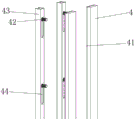
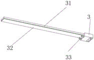
In the figure: 1. a well wall; 2. a support frame; 21. a first bolt; 22. a chute; 221. a fixing plate; 222. a second bolt; 3. sleeving a block; 31. a connecting rod; 32. a first cushioning pad; 33. a support bar; 4. fixing the rod; 41. a second cushioning pad; 42. a third bolt; 43. a guide rail bracket; 44. a U-shaped groove; 45. a first connecting plate; 46. a second connecting plate; 47. and a fourth bolt.
Detailed description of the preferred embodiments
The technical solutions in the embodiments of the present invention will be described clearly and completely with reference to the accompanying drawings in the embodiments of the present invention, and it is obvious that the described embodiments are only some embodiments of the present invention, not all embodiments. Based on the embodiments in the present invention, all other embodiments obtained by a person skilled in the art without creative efforts all belong to the protection scope of the present invention.
In order to facilitate understanding of the present invention, the present invention will be described more fully hereinafter with reference to the accompanying drawings. Several embodiments of the invention are presented in the drawings. The invention may, however, be embodied in many different forms and should not be construed as limited to the embodiments set forth herein. Rather, these embodiments are provided so that this disclosure will be thorough and complete.
It will be understood that when an element is referred to as being "secured to" another element, it can be directly on the other element or intervening elements may also be present. When an element is referred to as being "connected" to another element, it can be directly connected to the other element or intervening elements may also be present. The terms "vertical," "horizontal," "left," "right," and the like as used herein are for illustrative purposes only.
Unless defined otherwise, all technical and scientific terms used herein have the same meaning as commonly understood by one of ordinary skill in the art to which this invention belongs. The terminology used in the description of the invention herein is for the purpose of describing particular embodiments only and is not intended to be limiting of the invention. As used herein, the term "and/or" includes any and all combinations of one or more of the associated listed items.
Referring to fig. 1-5, the present invention provides a technical solution:
the utility model provides a car guide rail bracket for express elevator, includes well wall 1, its characterized in that: well wall 1 is equipped with two sets ofly, and 1 inboard side surface of well wall is close to the equal fixedly connected with support frame 2 of center department, the equal fixedly connected with spout 22 in front end left and right sides surface of support frame 2, and the inside upper and lower side of spout 22 all is equipped with nested piece 3, the equal fixedly connected with dead lever 4 in bottom left side surface of nested piece 3, and the equal fixedly connected with second bradyseism pad 41 of front side surface of dead lever 4 drives the inside nested piece 3 that is equipped with through spout 22 and removes.
It should be supplemented that the front side surfaces of the set blocks 3 are fixedly connected with connecting rods 31, the lower parts of the connecting rods 31 are fixedly connected with first shock absorption pads 32, and the connecting rods 31 are fixedly connected with the set blocks 3 and the set blocks 3 are fixed between the set blocks 3.
Preferably, two sets of support rods 33 are fixedly connected between the sleeve block 3 and the first shock absorbing pad 32 near the front side surface of the sleeve block 3, and the two sets of support rods 33 are fixedly connected between the first shock absorbing pad 32 and the sleeve block 3 to support the first shock absorbing pad 32 and the sleeve block 3.
Preferably, the left side and the right side of the surface of the support frame 2 are both provided with a plurality of groups of first bolts 21, the front end surface of the sleeve block 3 is both fixedly connected with a second connecting plate 46, the left side surface and the right side surface of the sliding groove 22 are both fixedly connected with a plurality of groups of fixing plates 221, the surface of each fixing plate 221 is all connected with two groups of second bolts 222 in a penetrating manner, the support frame 2 and the shaft wall 1 are fixed by the first bolts 21, the sliding groove 22 is fixed on the surface of the support frame 2 by the fixing plates 221, and the fixing plates 221 are fixed by the second bolts 222.
Preferably, the bottom ends of the second connecting plates 46 are fixedly connected with the first connecting plates 45, two sets of fourth bolts 47 are fixedly connected between the second connecting plates 46 and the first connecting plates 45, and the fourth bolts 47 are fixed between the first connecting plates 45 and the second connecting plates 46.
It is worth to say that the inboard surface of second bradyseism pad (41) all has a multiunit third bolt (42) through connection, multiunit third bolt (42) all has a guide rail frame (43) through connection, the inside surface of guide rail frame (43) is close to center department and all has seted up multiunit U-shaped groove (44), and third bolt 42 runs through U-shaped groove 44 and is fixed in inside second bradyseism pad 41.
The utility model discloses a car guide rail support for high-speed elevator is when using, it removes to drive inside nested piece 3 that is equipped with through spout 22, connecting rod 31 fixed connection fixes nested piece 3 between nested piece 3, two sets of bracing pieces 33 fixed connection support first bradyseism pad 32 and nested piece 3 between first bradyseism pad 32 and nested piece 3, first bolt 21 fixed stay frame 2 and well wall 1, fixed spout 22 of fixed plate 221 is on the surface of support frame 2, second bolt 222 fixed plate 221, four bolt 47 are fixed in between first connecting plate 45 and second connecting plate 46, third bolt 42 runs through inside U type groove 44 is fixed in second bradyseism pad 41.
The foregoing shows and describes the general principles, essential features, and advantages of the invention. It should be understood by those skilled in the art that the present invention is not limited by the above embodiments, and the description in the above embodiments and the description is only preferred examples of the present invention, and is not intended to limit the present invention, and that the present invention can have various changes and modifications without departing from the spirit and scope of the present invention, and these changes and modifications all fall into the scope of the claimed invention. The scope of the invention is defined by the appended claims and equivalents thereof.
Claims (6)
1. The utility model provides a car guide rail support for express elevator, includes well wall (1), its characterized in that: the utility model discloses a well wall, including well wall (1), well wall (1) inboard surface is close to the equal fixedly connected with support frame of center department (2), the equal fixedly connected with spout (22) in front end left and right sides surface of support frame (2), the inside top and bottom of spout (22) all is equipped with cover block (3), the equal fixedly connected with dead lever (4) in bottom left side surface of cover block (3), the equal fixedly connected with second bradyseism pad (41) of preceding side surface of dead lever (4).
2. The car guide rail bracket for the high-speed elevator according to claim 1, wherein: the equal fixedly connected with connecting rod (31) of front side surface of cover piece (3), the equal fixedly connected with first bradyseism pad (32) in below of connecting rod (31).
3. The car guide rail bracket for the high-speed elevator according to claim 2, wherein: two groups of support rods (33) are fixedly connected between the sleeve block (3) and the first shock absorption pad (32) and close to the surface of the front side of the sleeve block (3).
4. The car guide rail bracket for the high-speed elevator according to claim 1, wherein: the surperficial left and right sides of support frame (2) all is equipped with first bolt of multiunit (21), the equal fixedly connected with second connecting plate (46) in front end surface of cover piece (3), the equal fixedly connected with multiunit fixed plate (221) in left and right sides surface of spout (22), the surface of fixed plate (221) all through connection has two sets of second bolts (222).
5. The car guide rail bracket for the high-speed elevator according to claim 4, wherein: the bottom end of the second connecting plate (46) is fixedly connected with a first connecting plate (45), and two groups of fourth bolts (47) are fixedly connected between the second connecting plate (46) and the first connecting plate (45).
6. The car guide rail bracket for the high-speed elevator according to claim 1, wherein: the inboard surface of second bradyseism pad (41) all through connection has multiunit third bolt (42), multiunit third bolt (42) all through connection has guide rail frame (43), multiunit U-shaped groove (44) have all been seted up near center department to the inside surface of guide rail frame (43).
Priority Applications (1)
| Application Number | Priority Date | Filing Date | Title |
|---|---|---|---|
| CN202320193888.XU CN218860092U (en) | 2023-02-13 | 2023-02-13 | Car guide rail bracket for high-speed elevator |
Applications Claiming Priority (1)
| Application Number | Priority Date | Filing Date | Title |
|---|---|---|---|
| CN202320193888.XU CN218860092U (en) | 2023-02-13 | 2023-02-13 | Car guide rail bracket for high-speed elevator |
Publications (1)
| Publication Number | Publication Date |
|---|---|
| CN218860092U true CN218860092U (en) | 2023-04-14 |
Family
ID=87366068
Family Applications (1)
| Application Number | Title | Priority Date | Filing Date |
|---|---|---|---|
| CN202320193888.XU Active CN218860092U (en) | 2023-02-13 | 2023-02-13 | Car guide rail bracket for high-speed elevator |
Country Status (1)
| Country | Link |
|---|---|
| CN (1) | CN218860092U (en) |
-
2023
- 2023-02-13 CN CN202320193888.XU patent/CN218860092U/en active Active
Similar Documents
| Publication | Publication Date | Title |
|---|---|---|
| CN218860092U (en) | Car guide rail bracket for high-speed elevator | |
| CN204624901U (en) | Two steel band drives villa elevator | |
| CN204624903U (en) | Elevator car rack | |
| CN210505168U (en) | Foundation-pit-free elevator ascending and descending buffer device | |
| CN102408052A (en) | Counter-weight-free traction type passenger elevator | |
| CN210064946U (en) | Small frame for gantry crane | |
| CN210914864U (en) | Foundation-pit-free elevator anti-seismic connecting device | |
| CN216155255U (en) | Structural elevator for large load | |
| CN219384398U (en) | Light hydraulic traction elevator for home self-building | |
| CN207986441U (en) | A kind of elevator not taking up an area space of planes | |
| CN214643401U (en) | Assembly table suitable for different product models | |
| CN201850027U (en) | Traction passenger elevator without counter weight | |
| CN112623904A (en) | Elevator anti-falling centrifugal ball device | |
| CN219792094U (en) | Balance traction device of elevator | |
| CN217780446U (en) | Brake device for increasing brake contracting and releasing speed of elevator brake | |
| CN216326437U (en) | Intelligent elevator production and processing assembly line | |
| CN211687853U (en) | No computer lab cargo lift sedan-chair return pulley device | |
| CN113928957A (en) | Structural elevator for large load | |
| CN215797820U (en) | Assembled corner post for elevator car frame | |
| CN211419240U (en) | Tractor mounting frame for machine-room-free cargo elevator | |
| CN211004063U (en) | Special elevator for villa | |
| CN220431967U (en) | Elevator well | |
| CN216303012U (en) | Elevator energy-saving control system | |
| CN213923647U (en) | Vertical lift elevator with protection function | |
| CN212863672U (en) | Car stop device is used in elevator maintenance |
Legal Events
| Date | Code | Title | Description |
|---|---|---|---|
| GR01 | Patent grant | ||
| GR01 | Patent grant |