CN218856447U - Edge grinding device for optical lens - Google Patents
Edge grinding device for optical lens Download PDFInfo
- Publication number
- CN218856447U CN218856447U CN202320042661.5U CN202320042661U CN218856447U CN 218856447 U CN218856447 U CN 218856447U CN 202320042661 U CN202320042661 U CN 202320042661U CN 218856447 U CN218856447 U CN 218856447U
- Authority
- CN
- China
- Prior art keywords
- optical lens
- device body
- lens piece
- lifter
- handle
- Prior art date
- Legal status (The legal status is an assumption and is not a legal conclusion. Google has not performed a legal analysis and makes no representation as to the accuracy of the status listed.)
- Active
Links
- 230000003287 optical effect Effects 0.000 title claims abstract description 81
- 238000007688 edging Methods 0.000 claims abstract description 21
- 239000000428 dust Substances 0.000 claims description 7
- 239000011521 glass Substances 0.000 claims description 6
- 238000013016 damping Methods 0.000 abstract description 8
- 230000000694 effects Effects 0.000 abstract description 8
- 230000033001 locomotion Effects 0.000 abstract description 5
- 230000006872 improvement Effects 0.000 abstract description 3
- 229910001651 emery Inorganic materials 0.000 abstract description 2
- 238000005498 polishing Methods 0.000 description 12
- 238000009434 installation Methods 0.000 description 6
- 230000007246 mechanism Effects 0.000 description 4
- 238000004519 manufacturing process Methods 0.000 description 3
- 239000005304 optical glass Substances 0.000 description 3
- 238000000926 separation method Methods 0.000 description 3
- 241000252254 Catostomidae Species 0.000 description 2
- 230000008859 change Effects 0.000 description 2
- 238000005516 engineering process Methods 0.000 description 2
- 230000004048 modification Effects 0.000 description 2
- 238000012986 modification Methods 0.000 description 2
- 238000010521 absorption reaction Methods 0.000 description 1
- 230000009471 action Effects 0.000 description 1
- 230000000712 assembly Effects 0.000 description 1
- 238000000429 assembly Methods 0.000 description 1
- 230000002457 bidirectional effect Effects 0.000 description 1
- 230000005540 biological transmission Effects 0.000 description 1
- 238000010924 continuous production Methods 0.000 description 1
- 238000010586 diagram Methods 0.000 description 1
- 238000009826 distribution Methods 0.000 description 1
- 230000003028 elevating effect Effects 0.000 description 1
- 238000000034 method Methods 0.000 description 1
- 230000003595 spectral effect Effects 0.000 description 1
Images

Classifications
-
- Y—GENERAL TAGGING OF NEW TECHNOLOGICAL DEVELOPMENTS; GENERAL TAGGING OF CROSS-SECTIONAL TECHNOLOGIES SPANNING OVER SEVERAL SECTIONS OF THE IPC; TECHNICAL SUBJECTS COVERED BY FORMER USPC CROSS-REFERENCE ART COLLECTIONS [XRACs] AND DIGESTS
- Y02—TECHNOLOGIES OR APPLICATIONS FOR MITIGATION OR ADAPTATION AGAINST CLIMATE CHANGE
- Y02P—CLIMATE CHANGE MITIGATION TECHNOLOGIES IN THE PRODUCTION OR PROCESSING OF GOODS
- Y02P40/00—Technologies relating to the processing of minerals
- Y02P40/50—Glass production, e.g. reusing waste heat during processing or shaping
- Y02P40/57—Improving the yield, e-g- reduction of reject rates
Landscapes
- Grinding And Polishing Of Tertiary Curved Surfaces And Surfaces With Complex Shapes (AREA)
Abstract
The utility model discloses an optical lens piece edging device, the device comprises a device body, the upper surface of device body link up and is provided with the lifter, and the upper end of lifter is provided with the handle. The utility model discloses in, place optical lens piece between two sucking discs, the sucking disc is drawn close to the centre under damping spring's effect, fixes the centre gripping to optical lens piece, later rotates two-way lead screw through the handle for two carriage release lever relative motion, and then adjust the interval between two polishers according to optical lens piece's specification, adjust the inclination of polisher simultaneously, stimulate the lifter downwards through the handle at last for the emery wheel of polisher contacts with optical lens piece, polishes the operation to optical lens piece, the utility model discloses simple structure, convenient operation can polish the operation to the optical lens piece of different specifications, makes optical lens piece's edge personally submit the arc structure, improves its smoothness, very big improvement the practicality of device.
Description
Technical Field
The utility model relates to an optical lens piece processing technology field especially relates to an optical lens piece edging device.
Background
The optical glass is glass which can change the propagation direction of light and change the relative spectral distribution of ultraviolet light, visible light or infrared light, the optical glass can be used for manufacturing lenses, prisms, reflectors and the like in optical instruments, qualified optical glass is heated, forged and pressed to form an optical lens blank, the blank of the optical lens needs to be subjected to edging treatment, and a special edging processing device is usually adopted to edging the optical lens.
Through searching, the publication number is: CN216883124U an optical lens edging device for production, including support frame, rotating turret, roof, fixed mounting panel, lens positioning mechanism, extension frame and grinding mechanism, the rotating turret rotates to locate on the support frame, the roof locates on the rotating turret, the fixed mounting panel locates on rotating turret and locates below the roof, the lens positioning mechanism locates on fixed mounting panel and roof evenly at interval, the extension frame locates on support frame and extends to one side of the rotating turret, the grinding mechanism locates on extension frame, there are power cavities on the support frame, there are intermittent drive assemblies in the power cavity, the said intermittent drive assembly is connected with rotating turret; the intermittent transmission assembly comprises a sleeve shaft, a power shaft, a rotating sleeve, a first telescopic rod, a connecting rod and a braking and stopping sheet. The utility model relates to an optical lens piece processing technology field specifically is to provide but optical lens piece edging device is used in production of multistation continuous production.
The prior art has the following problems:
above-mentioned utility model adopts the operation of polishing to optical lens piece of the roller of polishing that has the spill structure, makes optical lens piece's side and surface be arc column structure, improves optical lens piece's smoothness nature, but the structure of the roller of polishing is fixed, can only polish the operation to single optical lens piece, and the practicality is lower.
We therefore propose an optical lens edging device that solves the above drawbacks.
SUMMERY OF THE UTILITY MODEL
The utility model aims at solving the structure of the roller of polishing that exists among the prior art and being fixed, can only polish the operation to single optical lens piece, the lower shortcoming of practicality, and an optical lens piece edging device that proposes.
In order to achieve the above purpose, the utility model adopts the following technical scheme: the utility model provides an optical lens piece edging device, includes the device body, the upper surface of device body link up and is provided with the lifter, and the upper end of lifter is provided with the handle, the lower tip of lifter is provided with the lifter plate, two-way lead screw is installed through the fixed block to the lower surface of lifter plate, and the tip of two-way lead screw installs the handle, the surface of two-way lead screw is provided with the carriage release lever, the polisher is installed through the pivot to the tip of carriage release lever, the interior bottom surface of device body is provided with the grip block, the side of grip block is full to link up and installs the supporting rod, and the one end of supporting rod installs the handle, the mount pad is installed to the other end of supporting rod, one side of mount pad is provided with driving motor, the mounting panel is installed to driving motor's output, and the surface of mounting panel is provided with the sucking disc, the surface of supporting rod is provided with damping spring.
Preferably, the inner bottom surface of the device body is provided with positioning seats, the outer surfaces of the positioning seats are in an annular array shape and are provided with electric telescopic rods, and the end parts of the electric telescopic rods are provided with positioning wheels.
Preferably, the side surface of the lifting rod is provided with grooves at equal intervals, the grooves are internally provided with lugs, the lugs are positioned in the side wall of the device body and provided with through holes, and one side of each lug is provided with a telescopic spring.
Preferably, a sliding rod is arranged inside the device body and is in sliding connection with the lifting plate.
Preferably, a dust collector is mounted through a side surface of the apparatus body.
Preferably, a box door is installed on the front surface of the device body through a hinge, and a glass window is arranged on the surface of the box door.
Preferably, the lower surface of the device body is provided with a plurality of foot pads, and the foot pads are distributed on the lower surface of the device body in a rectangular array manner.
Compared with the prior art, the utility model has the advantages that;
(1) The utility model discloses, through setting up the device body, the lifter, the handle, the lifter plate, the fixed block, two-way lead screw, the carriage release lever, the polisher, the handle, the grip block, the supporting rod, the handle, damping spring, the mount pad, the mounting panel, driving motor and sucking disc, the structure of having solved current grinding roller is fixed, can only polish the operation to single optical lens, the lower problem of practicality, during the use, place optical lens between two sucking discs, the sucking disc is drawn close to the centre under damping spring's effect, fix the centre gripping to optical lens, later rotate two-way lead screw through the handle, make two carriage release lever relative motion, and then adjust the interval between two polishers according to optical lens's specification, adjust the inclination of polisher simultaneously, stimulate the lifter downwards through the handle at last, make the polishing wheel of polisher contact with optical lens, polish the operation to optical lens, the utility model discloses simple structure, convenient operation can polish the operation to the optical lens of different specifications, make optical lens's edge personally submit the arc structure, improve its smoothness, very big practicality that has improved the device.
(2) The utility model discloses, through setting up the positioning seat, electric telescopic handle and locating wheel, when using, place optical lens piece in the positioning seat, later start electric telescopic handle, electric telescopic handle drive locating wheel, make locating wheel and optical lens piece hug closely mutually, make optical lens piece be in the center department of a plurality of locating wheels, later hug closely sucking disc and optical lens piece mutually, later restart electric telescopic handle again, make locating wheel and optical lens piece separation, thereby accomplish optical lens piece's location installation, avoid optical lens piece installation dislocation, influence the effect of polishing.
Drawings
In order to more clearly illustrate the embodiments of the present invention or the technical solutions in the prior art, the drawings required for the embodiments will be briefly described below.
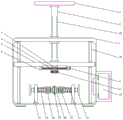
Fig. 1 is a schematic structural view of an optical lens edge grinding device according to the present invention;
fig. 2 is a schematic structural diagram of an internal portion of an optical lens edging device according to the present invention;
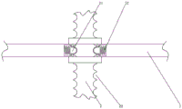
fig. 3 is a schematic structural view of a lifting rod portion of an optical lens edging device according to the present invention;
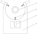
fig. 4 is the utility model provides a positioning seat overall structure sketch map of optical lens piece edging device.
Illustration of the drawings:
1. a device body; 2. a lifting rod; 3. a handle; 4. a lifting plate; 5. a fixed block; 6. a bidirectional screw rod; 7. a travel bar; 8. a sander; 9. a handle; 10. a clamping plate; 11. a clamping rod; 12. a handle; 13. a damping spring; 14. a mounting seat; 15. a suction cup; 16. a box door; 17. a glass window; 18. a foot pad; 19. a slide bar; 20. a groove; 21. a bump; 22. a tension spring; 23. a vacuum cleaner; 24. positioning seats; 25. an electric telescopic rod; 26. positioning a wheel; 27. a drive motor; 28. and (7) mounting the plate.
Detailed Description
In order to make the objects, technical solutions and advantages of the present invention more apparent, the present invention will be described in further detail with reference to the accompanying drawings in combination with the following embodiments. It should be understood that the description is intended to be illustrative only and is not intended to limit the scope of the present invention. Moreover, in the following description, descriptions of well-known structures and techniques are omitted so as to not unnecessarily obscure the concepts of the present invention.
Referring to fig. 1-4, an optical lens edging device, including device body 1, the upper surface of device body 1 link up and is provided with lifter 2, and the upper end of lifter 2 is provided with handle 3, the lower tip of lifter 2 is provided with lifter plate 4, two-way lead screw 6 is installed through fixed block 5 to the lower surface of lifter plate 4, and the tip of two-way lead screw 6 installs handle 9, two-way lead screw 6's surface is provided with carriage release lever 7, polisher 8 is installed through the pivot in the tip of carriage release lever 7, the interior bottom surface of device body 1 is provided with grip block 10, grip block 10's side table is run through all to install supporting rod 11, and the one end of supporting rod 11 installs handle 12, mount pad 14 is installed to the other end of supporting rod 11, one side of mount pad 14 is provided with driving motor 27, mounting panel 28 is installed to driving motor 27's output, and mounting panel 28's surface is provided with sucking disc 15, the surface of supporting rod 11 is provided with damping spring 13.
In this embodiment: during the use, place optical lens piece between two sucking discs 15, sucking disc 15 is drawn close to the centre under damping spring 13's effect, fixes the centre gripping to optical lens piece, later rotates two-way lead screw 6 through handle 9 for two carriage release lever 7 relative motion, and then adjust the interval between two polisher 8 according to optical lens piece's specification, adjust polisher 8's inclination simultaneously, stimulate lifter 2 downwards through handle 3 at last, make polisher 8's the emery wheel and optical lens piece contact, polish the operation to optical lens piece, the utility model discloses simple structure, convenient operation can polish the operation to the optical lens piece of different specifications, makes optical lens piece's edge personally submit the arc structure, improves its smoothness, very big improvement the practicality of device.
Specifically, the inner bottom surface of the device body 1 is provided with a positioning seat 24, the outer surface of the positioning seat 24 is provided with an electric telescopic rod 25 in an annular array, and the end of the electric telescopic rod 25 is provided with a positioning wheel 26.
In this embodiment: place optical lens piece in positioning seat 24, later start electric telescopic handle 25, electric telescopic handle 25 drives locating wheel 26, make locating wheel 26 hug closely mutually with optical lens piece, make optical lens piece be in the center department of a plurality of locating wheels 26, later hug closely sucking disc 15 and optical lens piece mutually, later start electric telescopic handle 25 once more, make locating wheel 26 and optical lens piece separation, thereby accomplish optical lens piece's location installation, avoid optical lens piece installation dislocation, influence the effect of polishing.
Specifically, grooves 20 are equidistantly formed in the side surface of the lifting rod 2, a projection 21 is arranged inside each groove 20, the projection 21 is located in a through hole formed in the side wall of the device body 1, and a telescopic spring 22 is arranged on one side of the projection 21.
In this embodiment: through setting up lifter 2, recess 20, lug 21, through-hole and expanding spring 22, when using, expanding spring 22 carries out simple and easy fixed to lifter 2 in with the convex part propelling movement of lug 21 to the recess 20 of lifter 2 side surface, and then conveniently adjusts the height of polisher 8 and fixes.
Specifically, a slide rod 19 is arranged inside the device body 1, and the slide rod 19 is connected with the lifting plate 4 in a sliding manner.
In this embodiment: through setting up slide bar 19, play the guide effect to lifter plate 4 for lifter plate 4 elevating movement is more steady.
Specifically, a dust collector 23 is mounted to penetrate a side surface of the apparatus body 1.
In this embodiment: through setting up dust catcher 23 for carry out the dust absorption to the dust of polishing, avoid the dust piece to fly upward, influence the environment of polishing.
Specifically, a door 16 is attached to the front surface of the apparatus body 1 via a hinge, and a glass window 17 is provided on the surface of the door 16.
In this embodiment: through setting up chamber door 16, play sealed effect to device body 1, the condition of polishing of staff's direct observation optical lens is made things convenient for to the setting of glass window 17 simultaneously.
Specifically, the foot pad 18 is provided on the lower surface of the device body 1, and the foot pad 18 is provided in plurality, and the plurality of foot pads 18 are distributed on the lower surface of the device body 1 in a rectangular array.
In this embodiment: the foot pad 18 is arranged to support the device body 1.
The working principle is as follows: when the device is used, an optical lens is placed between the two suckers 15, the suckers 15 are drawn to the middle under the action of the damping springs 13 to fixedly clamp the optical lens, then the two-way screw rod 6 is rotated through the handle 9, so that the two moving rods 7 move relatively, the distance between the two polishers 8 is adjusted according to the specification of the optical lens, the inclination angle of the polisher 8 is adjusted at the same time, and finally the lifting rod 2 is pulled downwards through the handle 3, so that the polishing wheel of the polisher 8 is in contact with the optical lens, and the optical lens is polished; place optical lens piece in positioning seat 24, later start electric telescopic handle 25, electric telescopic handle 25 drives locating wheel 26, make locating wheel 26 hug closely mutually with optical lens piece, make optical lens piece be in the center department of a plurality of locating wheels 26, later hug closely sucking disc 15 and optical lens piece mutually, later start electric telescopic handle 25 once more, make locating wheel 26 and optical lens piece separation, thereby accomplish optical lens piece's location installation, avoid optical lens piece installation dislocation, influence the effect of polishing.
It should be understood that the above-described embodiments of the present invention are merely illustrative of or explaining the principles of the invention and are not to be construed as limiting the invention. Therefore, any modification, equivalent replacement, improvement and the like made without departing from the spirit and scope of the present invention should be included in the protection scope of the present invention. Further, it is intended that the appended claims cover all such variations and modifications as fall within the scope and boundaries of the appended claims or the equivalents of such scope and boundaries.
Claims (7)
1. The utility model provides an optical lens edging device, includes device body (1), its characterized in that, the upper surface of device body (1) link up and is provided with lifter (2), and the upper end of lifter (2) is provided with handle (3), the lower tip of lifter (2) is provided with lifter plate (4), two-way lead screw (6) are installed through fixed block (5) to the lower surface of lifter plate (4), and the tip of two-way lead screw (6) installs handle (9), the surface of two-way lead screw (6) is provided with carriage release lever (7), polisher (8) are installed through the pivot to the tip of carriage release lever (7), the interior bottom surface of device body (1) is provided with grip block (10), the side table of grip block (10) is full to link up and installs mounting bar (11), and the one end of grip block (11) installs handle (12), mount pad (14) are installed to the other end of grip block (11), one side of mount pad (14) is provided with driving motor (27), mounting panel (28) are installed to the output of driving motor (27), and the surface of mounting panel (28) is provided with clamping bar (11), clamping spring (13) surface sucking disc (13).
2. An optical lens edging device according to claim 1, characterized in that the inner bottom surface of the device body (1) is provided with positioning seats (24), the outer surfaces of the positioning seats (24) are provided with electric telescopic rods (25) in an annular array, and the ends of the electric telescopic rods (25) are provided with positioning wheels (26).
3. An optical lens edging device according to claim 1, characterized in that the side surface of the lifting rod (2) is provided with grooves (20) at equal intervals, the inside of the groove (20) is provided with a projection (21), the projection (21) is positioned in a through hole formed in the side wall of the device body (1), and one side of the projection (21) is provided with a telescopic spring (22).
4. An optical lens edging device according to claim 1, characterized in that said device body (1) is internally provided with a sliding rod (19), and in that the sliding rod (19) is slidingly connected to the lifting plate (4).
5. An optical lens edging device according to claim 1, characterized in that a dust collector (23) is mounted through the lateral surface of the device body (1).
6. An optical lens edging device according to claim 1, characterized in that a door (16) is mounted to the front face of said device body (1) by means of hinges, and in that the surface of said door (16) is provided with a glass window (17).
7. An optical lens edging device according to claim 1, characterized in that the lower surface of the device body (1) is provided with a foot pad (18), and the foot pad (18) is provided in plurality, and the plurality of foot pads (18) are distributed on the lower surface of the device body (1) in a rectangular array.
Priority Applications (1)
| Application Number | Priority Date | Filing Date | Title |
|---|---|---|---|
| CN202320042661.5U CN218856447U (en) | 2023-01-06 | 2023-01-06 | Edge grinding device for optical lens |
Applications Claiming Priority (1)
| Application Number | Priority Date | Filing Date | Title |
|---|---|---|---|
| CN202320042661.5U CN218856447U (en) | 2023-01-06 | 2023-01-06 | Edge grinding device for optical lens |
Publications (1)
| Publication Number | Publication Date |
|---|---|
| CN218856447U true CN218856447U (en) | 2023-04-14 |
Family
ID=87366479
Family Applications (1)
| Application Number | Title | Priority Date | Filing Date |
|---|---|---|---|
| CN202320042661.5U Active CN218856447U (en) | 2023-01-06 | 2023-01-06 | Edge grinding device for optical lens |
Country Status (1)
| Country | Link |
|---|---|
| CN (1) | CN218856447U (en) |
-
2023
- 2023-01-06 CN CN202320042661.5U patent/CN218856447U/en active Active
Similar Documents
| Publication | Publication Date | Title |
|---|---|---|
| CN209936539U (en) | Gear deburring device for automobile manufacturing | |
| CN218697017U (en) | A grinding device for optical lenses | |
| CN114770338A (en) | Burnishing device is used in overware production | |
| CN217860501U (en) | Optical lens piece refiner | |
| CN213439095U (en) | Clamping and limiting mechanism for special-shaped edge grinding machine | |
| CN217232801U (en) | Portable curtain wall construction auxiliary device | |
| CN216859224U (en) | Electric motor car reflection of light lens accessory processing is with rotatory grinding device of centre gripping | |
| CN215588791U (en) | Vamp polishing polisher is used in leather shoe production | |
| CN214549227U (en) | Glass curtain wall cleaning robot | |
| CN215401726U (en) | Square toughened glass processing is with transport sucking disc | |
| CN212496884U (en) | A grinding machine for building decoration | |
| CN211394629U (en) | Equipment for repairing laser cladding of main driving runway of shield machine | |
| CN222874105U (en) | Lens burnishing device convenient to angle regulation | |
| CN219131783U (en) | Adjustable optical glass grinding and polishing device | |
| CN223406746U (en) | A double-arm lens adsorption mechanism for polishing optical lenses | |
| CN218518331U (en) | Telescope lens polishing equipment | |
| CN217619642U (en) | Edging device for processing electric automobile rearview mirror | |
| CN223876713U (en) | Polishing and grinding device for optical element production | |
| CN219967501U (en) | Polishing machine support capable of rotating in multiple directions | |
| CN216359481U (en) | Lens edging machine | |
| CN218904924U (en) | Positioning device for edging of vehicle-mounted lens | |
| CN219094743U (en) | Ceramic tile blank throwing machine | |
| CN221455370U (en) | Main shaft slope grinding equipment | |
| CN221135300U (en) | Edge polishing and polishing equipment for high-safety acrylic plate | |
| CN217860408U (en) | Picture frame production surface grinding machanism |
Legal Events
| Date | Code | Title | Description |
|---|---|---|---|
| GR01 | Patent grant | ||
| GR01 | Patent grant |