CN218840000U - Novel automatic bag feeding, filling and packaging machine - Google Patents
Novel automatic bag feeding, filling and packaging machine Download PDFInfo
- Publication number
- CN218840000U CN218840000U CN202220407337.4U CN202220407337U CN218840000U CN 218840000 U CN218840000 U CN 218840000U CN 202220407337 U CN202220407337 U CN 202220407337U CN 218840000 U CN218840000 U CN 218840000U
- Authority
- CN
- China
- Prior art keywords
- bag
- feeding
- supporting
- packaging
- filling
- Prior art date
- Legal status (The legal status is an assumption and is not a legal conclusion. Google has not performed a legal analysis and makes no representation as to the accuracy of the status listed.)
- Expired - Fee Related
Links
Images




Landscapes
- Supplying Of Containers To The Packaging Station (AREA)
Abstract
Description
技术领域technical field
本实用新型涉及包装设备的技术领域,特别涉及一种新型自动给袋填充包装机。The utility model relates to the technical field of packaging equipment, in particular to a novel automatic bag filling and packaging machine.
背景技术Background technique
随着近些年人们生活品质的提高,坚果行业不断发展,需要采用包装机近些包装,而目前市场上包装机的夹取运输装置通常是大型设备,当通过包装机进行夹取运输时,由于坚果包装袋大多采用双层包装袋,且大多包装机的撑袋机构适用于夹取单个包装袋,使该双层包装袋在夹取运输过程中不方便填装,从而导致包装困难,浪费包装时间,且给袋机构的作用是将袋仓内叠加的空包装袋一个个水平放置到给袋平台上,然而由于袋仓内叠加的空包装袋上下之间总会不整齐,当吸嘴将空包装袋吸住并放到给袋平台上后,给袋平台上的空包装袋的位置不是固定的,会存在不同程度的偏差,由于给袋位置的不准确,所以由上袋机构的夹钳夹住输送的空包装袋在到达转盘机构后也就存在偏差,从而导致包装质量不稳定。With the improvement of people's quality of life in recent years, the nut industry continues to develop, and it is necessary to use packaging machines for close packaging. At present, the clamping and transporting devices of packaging machines on the market are usually large-scale equipment. When clamping and transporting through packaging machines, Since most nut packaging bags use double-layer packaging bags, and the bag-holding mechanism of most packaging machines is suitable for clamping a single packaging bag, it is inconvenient to fill the double-layer packaging bag during clamping and transportation, resulting in packaging difficulties and waste Packaging time, and the role of the bag feeding mechanism is to place the empty bags superimposed in the bag bin horizontally on the bag feeding platform one by one. After sucking the empty packaging bag and putting it on the bag feeding platform, the position of the empty packaging bag on the bag feeding platform is not fixed, and there will be deviations to varying degrees. Due to the inaccurate position of the bag feeding, it is controlled by the bag loading mechanism. The empty packaging bag conveyed by the tongs clamps the deviation after reaching the turntable mechanism, resulting in unstable packaging quality.
实用新型内容Utility model content
本实用新型实施例所要解决的技术问题在于,提供一种新型自动给袋填充包装机,结构简单、输送整齐、开袋稳定高,双层包装袋全程由一个给袋夹爪夹持,并配合撑袋装置实现双层包装袋的开袋工作,有效提高生产效率以及包装质量。The technical problem to be solved by the embodiment of the utility model is to provide a new type of automatic bag filling and packaging machine, which has simple structure, neat conveying, high bag opening stability, and the double-layer packaging bag is clamped by a bag feeding jaw throughout the whole process, and cooperates with The bag support device realizes the opening work of double-layer packaging bags, which effectively improves production efficiency and packaging quality.
为达到上述目的,本实用新型公开了一种新型自动给袋填充包装机,包括旋转平台以及固接于旋转平台外缘的若干给袋夹爪,所述旋转平台由旋转驱动装置驱动自转联动所述给袋夹爪依次经过送袋夹爪、给袋装置、撑袋装置、下料装置;In order to achieve the above purpose, the utility model discloses a new type of automatic bag filling and packaging machine, which includes a rotating platform and a number of bag feeding jaws fixed on the outer edge of the rotating platform. The bag feeding jaws pass through the bag feeding jaws, the bag feeding device, the bag supporting device, and the unloading device in sequence;
所述给袋装置包括传送带、袋仓、下袋机构、上袋机构,所述袋仓上堆叠有若干包装袋,所述下袋机构吸取所述袋仓上的包装袋并下放于所述传送带上,通过所述传送带依次将包装袋向前输送,使所述上袋机构将所述传送带上的包装袋吸起,所述送袋夹爪用于夹取所述上袋机构上的双层包装袋,并将双层包装袋送入所述给袋夹爪上;The bag feeding device includes a conveyor belt, a bag bin, a bag lowering mechanism, and a bag loading mechanism. Several packaging bags are stacked on the bag bin, and the bag lowering mechanism absorbs the packaging bags on the bag bin and puts them down on the conveyor belt. On the conveyor belt, the packaging bags are sequentially conveyed forward, so that the bag-up mechanism can suck up the packaging bags on the conveyor belt, and the bag-feeding jaws are used to clamp the double layer on the bag-up mechanism. Pack the bag, and send the double-layer packing bag to the bag-feeding jaw;
所述撑袋装置包括撑袋臂以及转动设置于所述撑袋臂上成对的第一撑袋片、第二撑袋片,通过撑袋机构驱动所述第一、第二撑袋片将所述给袋夹爪上双层包装袋的两个袋口同步撑开,使所述下料装置将物料分别输入双层包装袋内。The bag-holding device includes a bag-holding arm and a pair of first bag-holding pieces and second bag-holding pieces that are rotatably arranged on the bag-holding arm, and the bag-holding mechanism drives the first and second bag-holding pieces to The two pockets of the double-layer packaging bag on the bag-feeding jaws are opened synchronously, so that the material unloading device can input materials into the double-layer packaging bag respectively.
优选的,袋仓包括第一臂板、第二臂板,所述第一、第二臂板上设置有托袋底板,使若干包装袋堆叠于所述托袋底板之间,所述第一、第二臂板的前端分别设置有前限位条,所述第一、第二臂板上设置有若干调节槽,所述调节槽之间均设置有后限位条,使双层包装袋的前、后端面限制于所述前限位条与所述后限位条之间。Preferably, the bag bin includes a first arm plate and a second arm plate, and the first and second arm plates are provided with a bag holder bottom plate, so that several packaging bags are stacked between the bag holder bottom plates, and the first arm plate 1. The front end of the second arm plate is respectively provided with front limit strips, and the first and second arm plates are provided with a number of adjustment grooves, and rear limit strips are arranged between the adjustment grooves, so that the double-layer packaging bag The front and rear end faces are limited between the front limiting strip and the rear limiting strip.
优选的,所述第一、第二臂板的外侧分别设置有托袋固定座,所述托袋底板固定设置于所述托袋固定座上,所述托袋底板的里侧面具有若干托袋插板,所述第一、第二臂板上设置有与托袋插板滑动插装的若干插槽。Preferably, the outer sides of the first and second arm plates are respectively provided with holding bag fixing seats, the bag holding bottom plate is fixedly arranged on the holding bag fixing seats, and the inner side of the bag holding bottom plate has several holding bags As for the inserting plate, the first and second arm plates are provided with a plurality of slots which are slidably inserted into the holding bag inserting plate.
优选的,所述前限位条之间设置有第一托爪,用于托住包装袋的前端,其中一所述后限位条上设置有第二托爪,用于托住双层包装袋的后端。Preferably, a first claw is provided between the front limiting strips for supporting the front end of the packaging bag, and a second claw is provided on one of the rear limiting strips for supporting the double-layer packaging the back end of the bag.
优选的,所述第一、第二臂板的后端下部分别设置有限位条,所述传送带的里侧面设置有限位底板,使包装袋的两侧限制于所述限位条与所述限位底板之间。Preferably, the lower parts of the rear ends of the first and second arm plates are respectively provided with limiting strips, and the inner side of the conveyor belt is provided with a limiting bottom plate, so that both sides of the packaging bag are limited by the limiting strips and the limiting strips. between the backplanes.
优选的,所述传送带的后端固定设置有挡袋前板,用于阻挡所述传送带上的双层包装袋,所述挡袋前板的中部固定设置有定位检测装置,用于检测双层包装袋的到位信息。Preferably, the rear end of the conveyor belt is fixedly provided with a bag-blocking front plate for blocking the double-layer packaging bags on the conveyor belt, and the middle part of the bag-stopping front plate is fixedly provided with a positioning detection device for detecting double-layer packaging bags. Information about the availability of the packaging bag.
优选的,所述撑袋机构均包括成对的第一撑袋座、第二撑袋座,所述第一、第二撑袋座均具有转轴部、支撑部、联动部,所述支撑部设置于所述转轴部的底部,所述联动部设置于所述转轴部的左侧,且所述第一、第二撑袋座的上部均具有弹力部,所述弹力部之间连接有拉力弹簧,所述撑袋臂的首端上转动设置有一转轴,所述第一、第二撑袋座的转轴部分别与所述转轴固定连接。Preferably, the bag-stretching mechanisms each include a pair of first bag-stretching seats and second bag-stretching seats, and the first and second bag-stretching seats each have a shaft portion, a support portion, and a linkage portion, and the support portion It is arranged at the bottom of the rotating shaft part, the linkage part is arranged on the left side of the rotating shaft part, and the upper parts of the first and second bag holders both have elastic parts, and a tension force is connected between the elastic parts. The first end of the bag-holding arm is rotatably provided with a rotating shaft, and the rotating shaft parts of the first and second bag-holding seats are respectively fixedly connected to the rotating shaft.
优选的,所述第一、第二撑袋座之间转动设置有翻转杆,所述翻转杆呈“L”形结构,所述翻转杆的上部转动设置有滚轮,所述滚轮与所述第一、第二撑袋座的联动部相抵触。Preferably, a turning bar is installed between the first and second bag holders, and the turning bar is in an "L" shape. The upper part of the turning bar is turned with a roller, and the rolling wheel and the first 1. The linkage part of the second bag holder is in conflict.
优选的,所述撑袋机构还包括连杆组件,所述连杆组件包括转杆、连杆,驱动装置,所述转杆上固定设置有拉杆,所述连杆的一端与所述拉杆转动连接,另一端与所述翻转杆的下端转动连接,通过驱动装置驱动所述转杆旋转,使所述连杆带动所述翻转杆上下摆动。Preferably, the bag supporting mechanism further includes a connecting rod assembly, the connecting rod assembly includes a rotating rod, a connecting rod, and a driving device, a pull rod is fixedly arranged on the rotating rod, and one end of the connecting rod rotates with the pulling rod connected, the other end is rotationally connected with the lower end of the turning rod, and the rotating rod is driven to rotate through the driving device, so that the connecting rod drives the turning rod to swing up and down.
优选的,所述第一、第二撑袋座的支撑部上分别固定设置有第一撑袋杆、第二撑袋杆,所述第一、第二撑袋片分别设置于所述第一、第二撑袋杆上。Preferably, the support parts of the first and second bag holders are respectively fixed with a first bag holder and a second bag holder, and the first and second bag holders are respectively arranged on the first bag holder. , On the second bag support rod.
相比于现有技术,本实用新型的有益效果在于:Compared with the prior art, the utility model has the beneficial effects of:
本实用新型袋仓的第一、第二臂板通过丝杆调整袋仓的宽度,从而能够根据双层包装袋的宽度调整第一、第二臂板之间的距离,第一、第二臂板上设置有前限位条、后限位条,使后限位板能够根据双层包装袋的长度调整与前限位条之间的距离,第一、第二臂板上设置有限位条,且传送带的侧壁设置有限位底板,双层包装袋的两侧在输送过程中滑入限位条与限位底板之间,从而提高包装袋表面与传送带表面之间的摩擦力,保证双层包装袋输送的稳定性。The first and second arm boards of the utility model adjust the width of the bag bin through screw rods, so that the distance between the first and second arm boards can be adjusted according to the width of the double-layer packaging bag. There are front limit strips and rear limit strips on the board, so that the distance between the rear limit plate and the front limit strip can be adjusted according to the length of the double-layer packaging bag, and the limit strips are set on the first and second arm plates , and the side wall of the conveyor belt is provided with a limit bottom plate, and the two sides of the double-layer packaging bag slide between the limit bar and the limit bottom plate during the conveying process, thereby increasing the friction between the surface of the packaging bag and the surface of the conveyor belt, ensuring double-layer packaging. The stability of layer packaging bag conveying.
托袋底板可调节设计,通过调节托袋底板之间的距离,从而能够增加包装袋两侧的支撑面积,并通过第一、第二托住配合限位底板托住双层包装袋的前、后端,有效防止双层包装袋的中部向下凹陷,从而提高软、硬包装袋的兼容性。The bottom plate of the support bag can be adjusted. By adjusting the distance between the bottom plates of the support bag, the support area on both sides of the packaging bag can be increased, and the front and bottom of the double-layer packaging bag can be supported by the first and second support and the limit bottom plate. The rear end effectively prevents the middle part of the double-layer packaging bag from sagging downwards, thereby improving the compatibility of soft and hard packaging bags.
撑袋机构采用两对撑袋片,且利用连杆机构控制撑袋片同步撑开双层包装袋的袋口,实现双层包装袋进行开袋,且采用连杆机构大大简化结构,通过撑袋检测装置能够检测双层包装袋的撑开情况,有效提高工作效率,降低生产成本,且提高撑袋的稳定性,杜绝包装袋撑袋不开情况下下料到袋外,造成物料的浪费。The bag support mechanism adopts two pairs of bag support pieces, and uses the link mechanism to control the bag support pieces to simultaneously open the pocket opening of the double-layer packaging bag, so as to realize the opening of the double-layer packaging bag, and the use of the link mechanism greatly simplifies the structure. The bag detection device can detect the opening of the double-layer packaging bag, which can effectively improve work efficiency, reduce production costs, and improve the stability of the bag, so as to prevent the material from being dropped out of the bag when the bag is not opened, resulting in waste of materials .
附图说明Description of drawings
图1为本实用新型的整体结构示意图;Fig. 1 is the overall structural representation of the utility model;
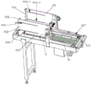
图2为给袋装置的整体结构示意图;Fig. 2 is the overall structure schematic diagram of bag feeding device;
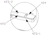
图3为托袋底板的整体结构示意图;Fig. 3 is a schematic diagram of the overall structure of the bottom plate of the bag holder;
图4为示出图3中的A部结构示意图;Fig. 4 is a schematic diagram showing the structure of part A in Fig. 3;
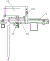
图5为下袋机构的整体结构示意图;Fig. 5 is a schematic diagram of the overall structure of the lower bag mechanism;
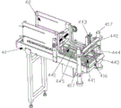
图6为上袋机构的整体结构示意图;Fig. 6 is a schematic diagram of the overall structure of the bagging mechanism;
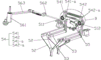
图7为撑袋装置的整体结构示意图I;Fig. 7 is the overall structure schematic diagram I of bag supporting device;
图8为撑袋机构的整体结构示意图II;Fig. 8 is a schematic diagram II of the overall structure of the bag-supporting mechanism;
图9示出图8中的B部结构示意图。FIG. 9 shows a schematic structural view of part B in FIG. 8 .
具体实施方式Detailed ways
为使本实用新型的目的、技术方案和优点更加清楚,下面将结合附图对本实用新型作进一步地详细描述。In order to make the purpose, technical solution and advantages of the utility model clearer, the utility model will be further described in detail below in conjunction with the accompanying drawings.
参照图1所示,一种新型自动给袋填充包装机,包括旋转平台1以及固接与旋转平台1外缘的若干给袋夹爪2,旋转平台1由旋转驱动装置驱动自转联动给袋夹爪2依次经过送袋夹爪3、给袋装置4、撑袋装置5、下料装置6。As shown in Figure 1, a new type of automatic bag filling and packaging machine includes a rotating platform 1 and a number of bag feeding jaws 2 fixed to the outer edge of the rotating platform 1. The claw 2 passes through the bag feeding jaw 3, the bag feeding device 4, the bag supporting device 5, and the unloading device 6 in sequence.
参照图2-图4所示,给袋装置4包括传送带41、袋仓42、下袋机构43、上袋机构44,袋仓42包括第一臂板421、第二臂板422,第一、第二臂板421、422 上设置有托袋底板423,第一、第二臂板421、422的外侧分别设置有托袋固定座423-1,托袋底板423固定设置于托袋固定座423-1上,托袋底板423的里侧面具有若干托袋插板423-2,第一、第二臂板421、422上设置有与托袋插板423-2 滑动插装的若干插槽424,即托袋底板423的若干托袋插板423-2通过插槽424 伸入第一、第二臂板421、422内,因此,通过托袋底板423的若干托袋插板423-2 分别托住包装袋的两侧下沿,使若干包装袋堆叠于袋仓42上,且托袋底板423 上设置有若干条形连接孔,本申请可根据包装袋的软硬程度调整托袋底板423 之间的距离,从而增加包装袋的支撑面积,避免因包装袋堆叠过多,导致包装袋在堆叠过程中其中部向下凹陷。Referring to Fig. 2-shown in Fig. 4, the bag feeding device 4 includes a
第一、第二臂板421、422的前端分别设置有前限位条425,使前限位条限制若干包装袋的前端,保证若干包装袋的前端之间保持整齐,第一、第二臂板 421、422上设置有若干调节槽426-1,调节槽426-1之间均设置有后限位条426,通过锁紧件穿过调节槽426-1与后限位条426固定连接,通过后限位条426配合前限位条425限制若干包装袋的后端,使包装袋的前、后端面限制于前限位条 425与后限位条426之间,保证若干包装袋的后端之间保持整齐,且本申请可根据包装袋的长度调节后限位条426的位置。The front ends of the first and
参照图2所示,前限位条425之间设置有第一托爪428,其中一所述后限位条上设置有第二托爪429,通过第一、第二托爪428、429配合托袋底板423分别托住包装袋的前、后端下沿,使包装袋的堆叠更加稳定,防止包装袋的中部向下凹陷。Referring to Fig. 2, a
参照图5所示,下袋机构43包括若干下袋吸嘴431,传送带41的下方固定设置有下袋驱动装置432,本实施例中优选采用气缸,其伸缩端上固定设置有吸袋板433,若干下袋吸嘴431分别设置于吸袋板433的两侧并连接有气源,通过下袋驱动装置432驱动下袋吸嘴431伸入袋仓42内,通过启动气源,使下袋吸嘴431吸附最底层的包装袋,接着在下袋驱动装置432的作用下将最底层的包装袋抽出袋仓42,并将包装袋下放于传送带41上,使传送带41将包装袋向前输送。Referring to Fig. 5, the
参照图3所示,更优的是,第一、第二臂板421、422的后端下部分别设置有限位条427,传送带41的里侧面设置有限位底板411,包装袋在输送过程中,使包装袋的两侧限制于限位条427与限位底板415之间,且限位条427作用于包装袋的表面上,从而增加包装袋的表面能够与传送带的表面之间的摩擦力,避免因包装袋表面的摩擦力不够使包装袋无法向前输送。Referring to Fig. 3, more preferably, the lower rear ends of the first and
参照图6所示,传送带41的后端固定设置有挡袋前板412,挡袋前板412 的中部固定设置有定位检测装置,本实施例中优选采用电光眼,通过挡袋前板 412阻挡传送带41上的包装袋继续前行,同时通过定位检测装置检测到包装袋到位,随即反馈给上袋机构4进行取袋。6, the rear end of the
参照图1、图6所示,上袋机构44包括若干上袋吸嘴441,传送带41的末端两侧设置有升降立柱417,升降立柱417的上部之间固定设置有上袋固定板 442,上袋固定板442上固定安装有上袋驱动装置443,本实施例中优选采用气缸,其伸缩端上设置有锁紧板444,锁紧板444的前、后端分别设置有若干吸嘴安装板445,若干上袋吸嘴441分别设置于吸嘴安装板445上,并连接有气源,通过启动气源,上袋驱动装置443驱动上袋吸嘴441下降,使上袋吸嘴441吸取包装袋的表面,接着在上袋驱动装置443的作用下将传送带41上的包装袋吸起,本申请可根据包装袋的长度调整吸嘴安装板445之间的距离,使上袋机构44能够对不同规格的包装袋进行吸取,通过送袋夹爪夹取上袋吸嘴上的包装袋并送至给袋夹爪上,本实施例中夹袋夹爪、送袋夹爪为现有公开技术,在此不做重复赘述。With reference to Fig. 1, shown in Fig. 6, bag-up
参照图1、图7、图8所示,撑袋装置5包括撑袋臂51、设置于撑袋臂51 的首端上成对的第一撑袋片52、第二撑袋片53,撑袋臂51的首端上转动设置有撑袋机构54,撑袋机构54均包括一对第一撑袋座541、541-a、一对第二撑袋座 542、542a,第一撑袋座541、541-a、第二撑袋座542、542-a均包括转轴部543、支撑部544、交叉部545,支撑部544设置于转轴部543的底部,交叉部545设置于撑袋臂51的端部,且第一撑袋座541、541-a与第二撑袋座542、542-a之间的交叉部545相对交错叠加,转轴部543的顶部设置有弹力部546,第一撑袋座 541、541-a与第二撑袋座542、542-a之间弹力部546连接有拉力弹簧,撑袋臂 51的首端上转动设置有一转轴511、512,第一撑袋座541、541-a、第二撑袋座 542、542a的转轴部分别与转轴511、512固定连接,且第一撑袋座541、541-a、第二撑袋座542、542-a的支撑部544上分别固定设置有第一撑袋杆547、第二撑袋杆548,第一、第二撑袋片52、53分别设置于第一、第二撑袋杆547、548上。With reference to Fig. 1, Fig. 7, shown in Fig. 8, bag-supporting device 5 comprises bag-supporting arm 51, is arranged on the head end of bag-supporting arm 51 paired first bag-supporting piece 52, the second bag-supporting piece 53, supports The head end of the bag arm 51 is provided with a bag-supporting mechanism 54 for rotation, and the bag-supporting mechanism 54 includes a pair of first bag-supporting seats 541, 541-a, a pair of second bag-supporting seats 542, 542a, the first bag-supporting seat 541, 541-a, and the second bag holder 542, 542-a all include a shaft portion 543, a support portion 544, and a cross portion 545, the support portion 544 is arranged at the bottom of the shaft portion 543, and the cross portion 545 is disposed on the bag stretcher arm 51 and the intersection 545 between the first bag spreader seat 541, 541-a and the second bag spreader seat 542, 542-a is relatively staggered and overlapped, and the top of the rotating shaft part 543 is provided with an elastic part 546, the first support A tension spring is connected to the elastic part 546 between the bag holder 541, 541-a and the second bag holder 542, 542-a, and a rotating shaft 511, 512 is arranged on the head end of the bag holder arm 51. The
参照图8、图9所示,第一撑袋座541、541-a、第二撑袋座542、542-b之间转动设置有翻转杆55,翻转杆55呈“L”形结构,翻转杆55的上部转动设置有滚轮551,滚轮551与第一撑袋座541、541-a、第二撑袋座542、542-a的交叉部 545相抵触,撑袋臂1上设置有连杆机构56,连杆机构56包括转杆561、连杆 562,连杆驱动装置,转杆561上固定设置有拉杆563,连杆562的一端与拉杆 563转动连接,另一端与翻转杆55的下部转动连接,通过连杆驱动装置驱动转杆561旋转,使连杆562联动翻转杆55上下摆动,从而控制成对的第一、第二撑袋片52、53相近或相离运动。Referring to Fig. 8 and Fig. 9, there is an overturn
当连杆机构56控制翻转杆55向上摆动,使翻转杆55的滚轮551将第一撑袋座541、541-a、第二撑袋座542、542-a的交叉部545顶起,从而联动第一、第二撑袋片52、53之间同步相近运动,则第一、第二撑袋片52、53不撑袋,当连杆机构56控制翻转杆55向下摆动,则第一撑袋座541、541-a、第二撑袋座542、 542-a之间在拉力弹簧的弹性作用下复位,使第一、第二撑袋片52、53之间同步相离运动并分别将双层包装袋的两个袋口撑开,通过下料装置6对双层包装袋进行填充物料,接着由转盘将装袋好的包装袋送入封口工位进行封口,本申请中下料装置为现有中的技术,在此不做重复赘述。When the
当然上述实施例只为说明本实用新型的技术构思及特点,其目的在于让熟悉此项技术的人能够了解本实用新型的内容并据以实施,并不能以此限制本实用新型的保护范围,凡根据本实用新型主要技术方案的精神实质所做的修饰,都应涵盖在本实用新型的保护范围之内。Certainly above-mentioned embodiment is only for explaining the technical conception and the characteristics of the present utility model, and its purpose is to allow people familiar with this technology to understand the content of the present utility model and implement accordingly, and can not limit the scope of protection of the present utility model with this, All modifications made according to the spirit of the main technical solutions of the utility model shall fall within the protection scope of the utility model.
Claims (10)
Priority Applications (1)
| Application Number | Priority Date | Filing Date | Title |
|---|---|---|---|
| CN202220407337.4U CN218840000U (en) | 2022-02-25 | 2022-02-25 | Novel automatic bag feeding, filling and packaging machine |
Applications Claiming Priority (1)
| Application Number | Priority Date | Filing Date | Title |
|---|---|---|---|
| CN202220407337.4U CN218840000U (en) | 2022-02-25 | 2022-02-25 | Novel automatic bag feeding, filling and packaging machine |
Publications (1)
| Publication Number | Publication Date |
|---|---|
| CN218840000U true CN218840000U (en) | 2023-04-11 |
Family
ID=87302523
Family Applications (1)
| Application Number | Title | Priority Date | Filing Date |
|---|---|---|---|
| CN202220407337.4U Expired - Fee Related CN218840000U (en) | 2022-02-25 | 2022-02-25 | Novel automatic bag feeding, filling and packaging machine |
Country Status (1)
| Country | Link |
|---|---|
| CN (1) | CN218840000U (en) |
Cited By (1)
| Publication number | Priority date | Publication date | Assignee | Title |
|---|---|---|---|---|
| CN117699146A (en) * | 2024-02-05 | 2024-03-15 | 山东斯马特农业科技有限公司 | Tea production packaging machine |
-
2022
- 2022-02-25 CN CN202220407337.4U patent/CN218840000U/en not_active Expired - Fee Related
Cited By (2)
| Publication number | Priority date | Publication date | Assignee | Title |
|---|---|---|---|---|
| CN117699146A (en) * | 2024-02-05 | 2024-03-15 | 山东斯马特农业科技有限公司 | Tea production packaging machine |
| CN117699146B (en) * | 2024-02-05 | 2024-04-16 | 山东斯马特农业科技有限公司 | Tea production packaging machine |
Similar Documents
| Publication | Publication Date | Title |
|---|---|---|
| KR101731582B1 (en) | Rotary packaging machine | |
| CN111268220A (en) | Automatic secondary bagging device and working method thereof | |
| CN108408138A (en) | A kind of set bag assembly pushing away pack mode suitable for side | |
| KR101185804B1 (en) | Sack feeding apparutus of automatic packing machine | |
| CN106275567A (en) | Cup class fragile article flexibility automatic packaging machine | |
| CN117342070B (en) | Disposable tableware batched bagging and tearing glue packaging machine | |
| CN111470093A (en) | Vertical placing type boxing system for soft infusion bag | |
| CN218839942U (en) | Bagged food packaging machine | |
| CN116280468A (en) | A fully automatic rice packaging machine | |
| CN209051666U (en) | A kind of automatic slash pocket machine | |
| CN207698124U (en) | Soup product bag-feeding type package machine | |
| CN116573231A (en) | A multi-bag synchronous bag feeding machine with an upper bag storage bin | |
| JP6978786B2 (en) | Self-supporting bag packaging device | |
| CN210853161U (en) | Automatic forming device that expandes of carton | |
| CN217375067U (en) | A high-speed tile packaging machine | |
| JPH05330528A (en) | Automatic uncasing, content taking-out, and folding device for case | |
| JP6364603B2 (en) | Bag feeding device and packaging machine provided with the same | |
| CN212172667U (en) | An infusion soft bag vertical packing system | |
| CN116902308B (en) | Automatic bag opening machine | |
| CN210761547U (en) | A cigarette bagging and sorting line | |
| CN109969478B (en) | Packaging method and application thereof in sheet packaging | |
| KR102474193B1 (en) | Pp bag feeding machine | |
| CN217805681U (en) | A horizontal bag feeding and suction bag device | |
| KR102365568B1 (en) | Packing bag automatic supply divide | |
| CN105691732A (en) | Transverse bag feeding packaging mechanism of tea leaf packaging machine |
Legal Events
| Date | Code | Title | Description |
|---|---|---|---|
| GR01 | Patent grant | ||
| GR01 | Patent grant | ||
| CF01 | Termination of patent right due to non-payment of annual fee | ||
| CF01 | Termination of patent right due to non-payment of annual fee |
Granted publication date: 20230411 |