CN218836448U - Workpiece tool of ultrasonic automatic welding machine - Google Patents
Workpiece tool of ultrasonic automatic welding machine Download PDFInfo
- Publication number
- CN218836448U CN218836448U CN202223010613.2U CN202223010613U CN218836448U CN 218836448 U CN218836448 U CN 218836448U CN 202223010613 U CN202223010613 U CN 202223010613U CN 218836448 U CN218836448 U CN 218836448U
- Authority
- CN
- China
- Prior art keywords
- fixture
- welding machine
- sleeve
- clamping block
- workpiece
- Prior art date
- Legal status (The legal status is an assumption and is not a legal conclusion. Google has not performed a legal analysis and makes no representation as to the accuracy of the status listed.)
- Active
Links
Images


Abstract
The utility model discloses an ultrasonic automatic welding machine's work piece frock, which comprises a rotating disk, be provided with a plurality of circumference array distribution that are on the carousel, can dismantle the fixture of being connected with the carousel, fixture includes the T template, upper surface one side of T template is provided with the stand, the top of stand is provided with the sleeve pipe with T template parallel distribution, sliding connection has the sliding plate in the sleeve pipe, the sleeve pipe one end is kept away from to the sliding plate is provided with first clamp splice, the utility model discloses make each fixture not interrelated, the work piece that can centre gripping alone and take has improved the practicality of device, and through the setting of T template on the fixture to and the setting in T type groove on the carousel, be convenient for install and dismantle fixture, when a certain fixture damages and needs to be changed, only need to twist the nut that corresponds on the fixture loose, can dismantle fixture and change easy operation, convenience.
Description
Technical Field
The utility model relates to an ultrasonic automatic welding machine technical field specifically is an ultrasonic automatic welding machine's work piece frock.
Background
The ultrasonic welding machine is mainly used for secondary connection of thermoplastic plastics, and compared with other traditional processes (such as gluing, electric ironing, screwing and the like), the ultrasonic welding machine has the remarkable advantages of high production efficiency, good welding quality, environmental protection, energy conservation and the like.
The ultrasonic welding machine is provided with a clamping mechanism for positioning a workpiece, and through retrieval, the Chinese patent No. (CN 216966622U) is provided, and the positioning tool for the ultrasonic mobile automatic welding machine relates to the technical field of welding positioning tool fixing and comprises a rotary table, wherein a motor is arranged at the bottom of the rotary table, a rotating shaft is fixed at the output end of the motor through spot welding, and one end of the rotating shaft is fixed with the bottom of the rotary table through spot welding; the utility model discloses install pivoted X type pole earlier on removing dish and fixed disk, install square piece of supporting on whole X type pole simultaneously, circular piece and the triangle of supporting is supported, correspond fixed different welding object respectively, simultaneously lift up the locking cap on the X type pole, make circular steering column and X type pole coincidence can realize the rotation of X type pole, holistic anchor clamps are adjusted comparatively conveniently, the free conversion of whole anchor clamps simultaneously, application scope is wider, the staff need not change different anchor clamps according to the shape size of welding article, when comparatively convenient, the whole welding efficiency of device has been improved. However, all clamping mechanisms used for clamping the workpiece in the patent technology are controlled through a threaded rod, but only one welding station is arranged in the ultrasonic welding machine, when the corresponding clamping mechanisms on the rotary table rotate to the position below the welding station, the welding station can only weld the workpiece, the welded workpiece can rotate out along with the rotary table, the workpiece to be welded needs to be taken out and installed, therefore, the clamping mechanisms only control all the clamping mechanisms through the threaded rod to simultaneously clamp the workpiece or loosen the workpiece, and the clamping mechanism is difficult to be applied to the ultrasonic welding machine for use.
SUMMERY OF THE UTILITY MODEL
An object of the utility model is to provide an ultrasonic automatic welding machine's work piece frock to solve the problem that proposes in the above-mentioned background art.
In order to achieve the above object, the utility model provides a following technical scheme:
the utility model provides an ultrasonic automatic welding machine's work piece frock, includes the carousel, be provided with a plurality of fixture that are circumference array distribution, can dismantle the connection with the carousel on the carousel, fixture includes the T template, upper surface one side of T template is provided with the stand, the top of stand is provided with the sleeve pipe with T template parallel distribution, sliding connection has the sliding plate in the sleeve pipe, sleeve pipe one end is kept away from to the sliding plate is provided with first clamp splice, sheathed tube upper surface is provided with can follow its length direction sliding connection's movable seat, be provided with the second clamp splice with first clamp splice relative distribution on the movable seat, just it is close to first clamp splice to promote the second clamp splice through many link mechanism on the sleeve pipe.
As a further aspect of the present invention: the upper surface of carousel is provided with a plurality of T type grooves that distribute with the fixture one-to-one, the size phase-match in T type plate size and T type groove, just the bottom inner wall middle part in T type groove is provided with the slotted hole along its length direction, the slotted hole is located carousel border one end and is the open type structure, just the bottom of T type plate is provided with two double-screw bolts, the bottom of double-screw bolt extends to slotted hole below and threaded connection has the nut.
As a further aspect of the present invention: the improved structure is characterized in that a movable cavity with two open ends is arranged in the middle of the inner cavity of the sleeve, the sliding plate is located in the inner cavity of the movable cavity and is in sliding connection with the movable cavity, a limiting groove is formed in the middle of the bottom of the sliding plate along the length direction of the sliding plate, a through hole is formed in the bottom of one end, close to the first clamping block, of the sleeve, a nut is arranged at the bottom of the through hole, a locking bolt is connected to the nut in an internal thread mode, and the top end of the locking bolt extends to the inner cavity of the movable cavity and is in contact with the inner wall of the top end of the limiting groove.
As a further aspect of the present invention: the middle part of the upper surface of the sleeve is provided with a trapezoidal groove along the length direction of the upper surface of the sleeve, one end of the trapezoidal groove, which is far away from the first clamping block, is of an open structure, the other end of the trapezoidal groove is of a closed structure, and the bottom of the movable seat is provided with a trapezoidal block which is in sliding connection with the trapezoidal groove.
As a further aspect of the present invention: many link mechanism includes two relative distribution's first connecting rod, two the upper surface that first clamp splice one end was all kept away from with the sleeve pipe through the pivot to the one end of first connecting rod rotates to be connected, and the other end all rotates through the pivot to be connected with the second connecting rod, two the upper surface that the pivot and sliding seat were passed through to the one end that first connecting rod was kept away from to the second connecting rod rotates to be connected, just the cover is equipped with the third connecting rod in the pivot of first connecting rod and second connecting rod junction, the bottom of third connecting rod rotates through the pivot and is connected with the regulating plate, the one end of regulating plate rotates through pivot and stand lateral wall to be connected, be provided with the spring between the upper surface of regulating plate and the stand lateral wall, just the one end that the stand was kept away from to the regulating plate sets up to the arc structure.
As a further aspect of the present invention: and one side of the first clamping block, which is opposite to the second clamping block, is provided with a V-shaped groove.
Compared with the prior art, the beneficial effects of the utility model are that:
1. the utility model discloses make each fixture not interrelated, the work piece of centre gripping and taking alone, the practicality of device has been improved, and through the setting of the last T template of fixture, and the setting in T type groove on the carousel, be convenient for install and dismantle fixture, during the installation, only need inject fixture's T template T type inslot, two double-screw bolts on the T template this moment are in the slotted hole, then screw up the nut on the double-screw bolt and can install fixedly to fixture, when a certain fixture damages and needs to be changed, only need to unscrew the nut that corresponds on the fixture, can dismantle fixture and get off to change, and is easy for operation, and is convenient.
2. Through the sliding connection of the sliding plate and the movable cavity of the sleeve, the distance between the first clamping block and the second clamping block can be conveniently adjusted, so that the first clamping block and the second clamping block can be conveniently adjusted to a proper distance according to the size of the batch of workpieces, the clamping mechanism can be suitable for workpieces of different batches, the flexibility is high, and the utilization rate is greatly improved.
3. Through the arrangement of the multi-connecting-rod mechanism, the workpiece can be clamped and taken quickly, the clamping fixing mode is simple and quick, redundant actions are not needed, and the improvement of the working efficiency is facilitated.
Drawings
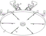
Fig. 1 is a schematic structural diagram of a workpiece fixture of an automatic ultrasonic welding machine.
Fig. 2 is a schematic structural view of fig. 1 from another view angle.
Fig. 3 is a schematic structural diagram of a turntable in a workpiece tool of an automatic ultrasonic welding machine.
Fig. 4 is a schematic structural diagram of a clamping mechanism in a workpiece tool of an automatic ultrasonic welding machine.
Fig. 5 is a schematic structural view of fig. 4 from another view angle.
FIG. 6 is an exploded view of the sleeve and slide plate in the workpiece assembly of an automatic ultrasonic welding machine.
In the figure: 1. a turntable; 2. a clamping mechanism; 3. a long round hole; 4. a T-shaped groove; 5. a T-shaped plate; 6. a column; 7. a stud; 8. a sleeve; 9. a sliding plate; 10. a first clamping block; 11. a movable seat; 12. a second clamp block; 13. a first link; 14. a second link; 15. a third link; 16. an adjusting plate; 17. a spring; 18. locking the bolt; 19. a limiting groove; 20. a movable cavity; 21. a trapezoidal groove; 22. a trapezoidal block.
Detailed Description
The technical solutions in the embodiments of the present invention will be described clearly and completely with reference to the accompanying drawings in the embodiments of the present invention, and it is obvious that the described embodiments are only some embodiments of the present invention, not all embodiments. Based on the embodiments in the present invention, all other embodiments obtained by a person skilled in the art without creative work belong to the protection scope of the present invention.
Referring to fig. 1 to 6, in an embodiment of the present invention, a workpiece fixture of an automatic ultrasonic welding machine includes a rotary table 1, a plurality of clamping mechanisms 2 distributed in a circumferential array and detachably connected to the rotary table 1 are disposed on the rotary table 1, each clamping mechanism 2 includes a T-shaped plate 5, an upright 6 is disposed on one side of an upper surface of the T-shaped plate 5, a sleeve 8 is disposed on a top end of the upright 6 and parallel to the T-shaped plate 5, a sliding plate 9 is slidably connected to the sleeve 8, a first clamping block 10 is disposed on one end of the sliding plate 9 away from the sleeve 8, a movable base 11 slidably connected along a length direction of the sleeve 8 is disposed on an upper surface of the sleeve 8, a second clamping block 12 is disposed on the movable base 11 and opposite to the first clamping block 10, V-shaped grooves are disposed on opposite sides of the first clamping block 10 and the second clamping block 12, and a V-shaped groove is disposed on an opposite side of the first clamping block 10 and the second clamping block 12 to facilitate clamping and fixing a workpiece, the middle part of the inner cavity of the sleeve 8 is provided with a movable cavity 20 with two open ends, the sliding plate 9 is positioned in the inner cavity of the movable cavity 20 and is in sliding connection with the movable cavity 20, the middle part of the bottom of the sliding plate 9 is provided with a limiting groove 19 along the length direction, the bottom of the sleeve 8 close to one end of the first clamping block 10 is provided with a through hole, the bottom of the through hole is provided with a nut, the nut is in threaded connection with a locking bolt 18, the top end of the locking bolt 18 extends to the inner cavity of the movable cavity 20 and is in contact with the inner wall of the top end of the limiting groove 19, the sliding plate 9 is in sliding connection with the movable cavity 20 of the sleeve 8, so that the distance between the first clamping block 10 and the second clamping block 12 can be conveniently adjusted to be proper according to the size of batch workpieces, and the clamping mechanism 2 can be suitable for workpieces with different batches, the flexibility is strong, the utilization rate is greatly improved, during adjustment, the locking bolt 18 is firstly unscrewed, the sliding plate 9 can slide, after the adjustment is finished, the locking bolt 18 is screwed, the trapezoidal groove 21 is formed in the middle of the upper surface of the sleeve 8 along the length direction of the sleeve, one end, away from the first clamping block 10, of the trapezoidal groove 21 is of an open structure, the other end of the trapezoidal groove 21 is of a closed structure, the bottom of the movable seat 11 is provided with a trapezoidal block 22 in sliding connection with the trapezoidal groove 21, through the matching between the trapezoidal block 22 and the trapezoidal groove 21, the movable seat 11 can move along the length direction of the sleeve 8, the second clamping block 12 can be close to the first clamping block 10 to clamp and fix a workpiece, or the second clamping block 12 is far away from the first clamping block 10, and the workpiece can be taken out;
the sleeve 8 pushes the second clamping block 12 to approach the first clamping block 10 through the multi-link mechanism, the multi-link mechanism comprises two first connecting rods 13 which are distributed oppositely, one ends of the two first connecting rods 13 are rotatably connected with the upper surface of one end of the sleeve 8 far away from the first clamping block 10 through rotating shafts, the other ends of the two first connecting rods 13 are rotatably connected with second connecting rods 14 through rotating shafts, one ends of the two second connecting rods 14 far away from the first connecting rods 13 are rotatably connected with the upper surface of the movable seat 11 through rotating shafts, a third connecting rod 15 is sleeved on the rotating shaft at the joint of the first connecting rods 13 and the second connecting rods 14, the bottom of the third connecting rod 15 is rotatably connected with an adjusting plate 16 through rotating shafts, one end of the adjusting plate 16 is rotatably connected with the side wall of the upright post 6 through rotating shafts, a spring 17 is arranged between the upper surface of the adjusting plate 16 and the side wall of the upright post 6, one end of the adjusting plate 16 far away from the upright post 6 is arranged to be of an arc structure, in an initial state, the spring 17 generates elastic force to the adjusting plate 16, so that the adjusting plate 16 moves away from the upright 6 and rotates downwards, so that the adjusting plate 16 drives the third connecting rod 15 to move downwards, so that the third connecting rod 15 pulls the first connecting rod 13, so that the first connecting rod 13 pushes the second connecting rod 14, at this time, the included angle between the first connecting rod 13 and the second connecting rod 14 gradually increases, so that the second connecting rod 14 pushes the second clamping block 12 to move towards one side of the first clamping block 10, when a workpiece needs to be fastened, the adjusting plate 16 is pulled upwards by hand, so that the adjusting plate 16 compresses the spring 17, so that the third connecting rod 15 moves upwards, so that the first connecting rod 13 pulls the second connecting rod 14, at this time, the included angle between the first connecting rod 13 and the second connecting rod 14 gradually decreases, so that the second connecting rod 14 pulls the second clamping block 12 to be away from the first clamping block 10, and then the workpiece is placed close to the first clamping block 10, then, the hand for pulling the adjusting plate 16 is loosened, the adjusting plate 16 is reset under the action of the elastic force of the spring 17, the four-point second clamping block 12 moves towards the first clamping block 10, the workpiece is clamped and fixed, after welding is completed, the workpiece can be taken out by pulling the adjusting plate 16, the clamping and fixing mode is simple and rapid, redundant actions are not needed, and the work efficiency is improved;
the upper surface of the rotary table 1 is provided with a plurality of T-shaped grooves 4 which are distributed in one-to-one correspondence with the clamping mechanisms 2, the sizes of the T-shaped plates 5 are matched with the sizes of the T-shaped grooves 4, long circular holes 3 are formed in the middle parts of the inner walls of the bottoms of the T-shaped grooves 4 along the length direction of the inner walls, one ends, located at the edges of the rotary table 1, of the long circular holes 3 are of an open structure, two studs 7 are arranged at the bottoms of the studs 5, extend to the positions below the long circular holes 3 and are connected with nuts in a threaded mode, the T-shaped plates 5 on the clamping mechanisms 2 are arranged, the T-shaped grooves 4 on the rotary table 1 are arranged, the clamping mechanisms 2 can be conveniently installed and disassembled, during installation, the T-shaped plates 5 of the clamping mechanisms 2 only need to be inserted into the T-shaped grooves 4, the two studs 7 on the T-shaped plates 5 are located in the long circular holes 3, then the clamping mechanisms 2 can be installed and fixed by screwing the nuts on the studs 7, when one clamping mechanism 2 is damaged and needs to be replaced, the clamping mechanism 2 only needs to be unscrewed, and the clamping mechanism 2 can be disassembled, and the clamping mechanism 2 can be replaced, and the clamping mechanism 2 is simple and convenient to replace.
The utility model discloses a theory of operation is:
when the welding device is used, a workpiece is placed on the clamping mechanism 2 to be fixed, the driving mechanism drives the rotary table 1 to rotate, the clamping mechanism 2 is rotated to the position below a welding station, the workpiece is welded through the welding station, after welding is finished, the rotary table 1 is rotated through the driving mechanism, the workpiece on the next clamping mechanism 2 is moved to the position below the welding station to be welded, the welded workpiece is rotated to a blanking station, the workpiece on the clamping mechanism 2 can be taken out through the lifting adjusting plate 16, the operation is repeated, the working efficiency is greatly improved, and when the batch of workpieces need to be replaced, the distance between the first clamping block 10 and the second clamping block 12 can be adjusted through the sliding plate 9 to adapt to the size of the workpiece.
The above, only be the embodiment of the preferred of the present invention, but the protection scope of the present invention is not limited thereto, and any person skilled in the art is in the technical scope of the present invention, according to the technical solution of the present invention and the utility model, which are designed to be replaced or changed equally, all should be covered within the protection scope of the present invention.
Claims (6)
1. A workpiece tool of an automatic ultrasonic welding machine comprises a rotary table (1) and is characterized in that a plurality of clamping mechanisms (2) which are distributed in a circumferential array and detachably connected with the rotary table (1) are arranged on the rotary table (1);
fixture (2) include T template (5), upper surface one side of T template (5) is provided with stand (6), the top of stand (6) is provided with sleeve pipe (8) with T template (5) parallel distribution, sliding connection has sliding plate (9) in sleeve pipe (8), sleeve pipe (8) one end is kept away from in sliding plate (9) is provided with first clamp splice (10), the upper surface of sleeve pipe (8) is provided with can follow its length direction sliding connection's movable seat (11), be provided with second clamp splice (12) with first clamp splice (10) relative distribution on movable seat (11), just promote second clamp splice (12) to be close to first clamp splice (10) through many link mechanism on sleeve pipe (8).
2. The workpiece tooling of the automatic ultrasonic welding machine according to claim 1 is characterized in that a plurality of T-shaped grooves (4) which are distributed in a one-to-one correspondence manner with the clamping mechanisms (2) are formed in the upper surface of the rotary table (1), the size of each T-shaped plate (5) is matched with the size of each T-shaped groove (4), long round holes (3) are formed in the middle of the inner wall of the bottom of each T-shaped groove (4) along the length direction of the bottom of each T-shaped groove, one end, located at the edge of the rotary table (1), of each long round hole (3) is of an open structure, two studs (7) are arranged at the bottom of each T-shaped plate (5), and the bottoms of the studs (7) extend to the lower portion of the long round holes (3) and are in threaded connection with nuts.
3. The workpiece fixture of the automatic ultrasonic welding machine as claimed in claim 1, wherein a movable cavity (20) with two open ends is arranged in the middle of the inner cavity of the sleeve (8), the sliding plate (9) is located in the inner cavity of the movable cavity (20) and is slidably connected with the movable cavity (20), a limiting groove (19) is arranged in the middle of the bottom of the sliding plate (9) along the length direction of the sliding plate, a through hole is formed in the bottom of one end, close to the first clamping block (10), of the sleeve (8), a nut is arranged at the bottom of the through hole, a locking bolt (18) is connected with the nut in a threaded manner, and the top end of the locking bolt (18) extends to the inner cavity of the movable cavity (20) and is in contact with the inner wall of the top end of the limiting groove (19).
4. The workpiece tool of the automatic ultrasonic welding machine as claimed in claim 1, wherein a trapezoidal groove (21) is formed in the middle of the upper surface of the sleeve (8) along the length direction of the sleeve, one end, away from the first clamping block (10), of the trapezoidal groove (21) is of an open structure, the other end of the trapezoidal groove (21) is of a closed structure, and a trapezoidal block (22) which is slidably connected with the trapezoidal groove (21) is arranged at the bottom of the movable seat (11).
5. The workpiece tool of the automatic ultrasonic welding machine according to claim 1, characterized in that the multi-link mechanism comprises two first connecting rods (13) which are distributed oppositely, two first connecting rods (13) are rotatably connected with the upper surface of one end of a first clamping block (10) away from a sleeve (8) through rotating shafts at one ends of the first connecting rods (13), second connecting rods (14) are rotatably connected with the other ends of the first connecting rods (13) through rotating shafts at the other ends of the first connecting rods (13) and the second connecting rods (14), a third connecting rod (15) is sleeved on the rotating shaft of the joint of the first connecting rod (13) and the second connecting rod (14), an adjusting plate (16) is rotatably connected with the bottom of the third connecting rod (15) through the rotating shafts, one end of the adjusting plate (16) is rotatably connected with the side wall of a stand column (6) through the rotating shafts, a spring (17) is arranged between the upper surface of the adjusting plate (16) and the side wall of the stand column (6), and one end, away from the adjusting plate (16), of the stand column (6), is arranged in an arc-shaped structure.
6. The workpiece fixture of the automatic ultrasonic welding machine as claimed in claim 1, wherein V-shaped grooves are formed in the opposite sides of the first clamping block (10) and the second clamping block (12).
Priority Applications (1)
| Application Number | Priority Date | Filing Date | Title |
|---|---|---|---|
| CN202223010613.2U CN218836448U (en) | 2022-11-12 | 2022-11-12 | Workpiece tool of ultrasonic automatic welding machine |
Applications Claiming Priority (1)
| Application Number | Priority Date | Filing Date | Title |
|---|---|---|---|
| CN202223010613.2U CN218836448U (en) | 2022-11-12 | 2022-11-12 | Workpiece tool of ultrasonic automatic welding machine |
Publications (1)
| Publication Number | Publication Date |
|---|---|
| CN218836448U true CN218836448U (en) | 2023-04-11 |
Family
ID=87309084
Family Applications (1)
| Application Number | Title | Priority Date | Filing Date |
|---|---|---|---|
| CN202223010613.2U Active CN218836448U (en) | 2022-11-12 | 2022-11-12 | Workpiece tool of ultrasonic automatic welding machine |
Country Status (1)
| Country | Link |
|---|---|
| CN (1) | CN218836448U (en) |
-
2022
- 2022-11-12 CN CN202223010613.2U patent/CN218836448U/en active Active
Similar Documents
| Publication | Publication Date | Title |
|---|---|---|
| CN212886313U (en) | Clamp combination for numerical control machining | |
| CN218836448U (en) | Workpiece tool of ultrasonic automatic welding machine | |
| CN211277972U (en) | Head burnishing machine frock clamp | |
| CN218224170U (en) | Simple pipe bending device | |
| CN213164193U (en) | Multi-angle adjustable clamp for numerical control machine tool | |
| CN206869354U (en) | Rotate horizontally vehicle switching flexible welding workbench | |
| CN214641791U (en) | Positioning fixture for machining | |
| CN220902418U (en) | Tank welding tool | |
| CN213827093U (en) | Bearing seat inner ring turning clamp convenient for taking and placing workpieces | |
| CN216775057U (en) | Stable connecting structure of electric heating plate | |
| CN219274712U (en) | Tapping machine fixture | |
| CN220971281U (en) | Steel welding jig | |
| CN220863058U (en) | Laser welding fixing device | |
| CN217859655U (en) | Welding jig for welding screws | |
| CN213889109U (en) | Welding and drilling tool clamping fixture for machine tool lifting seat | |
| CN215990663U (en) | Photovoltaic support of quick installation | |
| CN220836237U (en) | Rotatable clamping tool | |
| CN220592911U (en) | Tool clamp capable of automatically overturning | |
| CN216882817U (en) | Punching device with clamping and fixing mechanism for wind power blade | |
| CN214867918U (en) | Welding auxiliary device for two-protection electric welding machine | |
| CN218051402U (en) | Hydro-cylinder uide bushing adds clamping apparatus | |
| CN218366681U (en) | Frame-type hydraulic press is with removing stop device | |
| CN219616757U (en) | Deep hole bores processing frock | |
| CN220691878U (en) | Aluminum shell clamping equipment for patch type aluminum electrolytic capacitor | |
| CN212128914U (en) | Warning sign is used in electric power construction |
Legal Events
| Date | Code | Title | Description |
|---|---|---|---|
| GR01 | Patent grant | ||
| GR01 | Patent grant |