CN218819821U - Street lamp convenient to overhaul - Google Patents
Street lamp convenient to overhaul Download PDFInfo
- Publication number
- CN218819821U CN218819821U CN202222266301.1U CN202222266301U CN218819821U CN 218819821 U CN218819821 U CN 218819821U CN 202222266301 U CN202222266301 U CN 202222266301U CN 218819821 U CN218819821 U CN 218819821U
- Authority
- CN
- China
- Prior art keywords
- lamp
- rope
- lamp holder
- plate
- overhaul
- Prior art date
- Legal status (The legal status is an assumption and is not a legal conclusion. Google has not performed a legal analysis and makes no representation as to the accuracy of the status listed.)
- Active
Links
- 241000276425 Xiphophorus maculatus Species 0.000 claims description 18
- 230000000295 complement effect Effects 0.000 abstract description 5
- 230000009286 beneficial effect Effects 0.000 abstract description 2
- 238000004804 winding Methods 0.000 abstract 1
- 238000012423 maintenance Methods 0.000 description 7
- 238000005286 illumination Methods 0.000 description 4
- 238000000034 method Methods 0.000 description 4
- 230000005484 gravity Effects 0.000 description 2
- 238000009434 installation Methods 0.000 description 2
- 230000004075 alteration Effects 0.000 description 1
- 238000012986 modification Methods 0.000 description 1
- 230000004048 modification Effects 0.000 description 1
- 238000006467 substitution reaction Methods 0.000 description 1
Images



Classifications
-
- Y—GENERAL TAGGING OF NEW TECHNOLOGICAL DEVELOPMENTS; GENERAL TAGGING OF CROSS-SECTIONAL TECHNOLOGIES SPANNING OVER SEVERAL SECTIONS OF THE IPC; TECHNICAL SUBJECTS COVERED BY FORMER USPC CROSS-REFERENCE ART COLLECTIONS [XRACs] AND DIGESTS
- Y02—TECHNOLOGIES OR APPLICATIONS FOR MITIGATION OR ADAPTATION AGAINST CLIMATE CHANGE
- Y02B—CLIMATE CHANGE MITIGATION TECHNOLOGIES RELATED TO BUILDINGS, e.g. HOUSING, HOUSE APPLIANCES OR RELATED END-USER APPLICATIONS
- Y02B20/00—Energy efficient lighting technologies, e.g. halogen lamps or gas discharge lamps
- Y02B20/72—Energy efficient lighting technologies, e.g. halogen lamps or gas discharge lamps in street lighting
Landscapes
- Non-Portable Lighting Devices Or Systems Thereof (AREA)
Abstract
The utility model relates to a street lamp overhauls the field, specifically discloses a street lamp convenient to overhaul, street lamp convenient to overhaul includes: the lamp comprises a lamp post, a lamp holder is arranged on the surface of the lamp post in a sliding mode, and a limiting ring is arranged at the bottom of a side plate of the lamp post; the motor is arranged inside the lamp pole, a round rod is sleeved on an output shaft of the motor, and a rope is wound on the surface of the round rod; the wheel is rotationally arranged inside the lamp post through the supporting rod and the bearing, and the rope winds on the surface of the sliding plate at the end part of the lamp holder after winding around the wheel; the beneficial effects are that: one end of the rope is connected to the round rod on the output shaft of the motor, the other end of the rope is connected to the annular lifting lug at the top of the sliding plate after bypassing the wheel, the motor rotates to retract and release the rope to lift the lamp holder, the lamp holder is limited by the size of the limiting ring, the limiting rod and the strip-shaped opening, the structure is simple, safe and reliable, the lamp holder and the sliding plate are tightly connected through the plate with complementary shapes, and the lamp holder is convenient to detach and replace.
Description
Technical Field
The utility model relates to a street lamp overhauls the field, specifically is a street lamp convenient to overhaul.
Background
Street lamps, which refer to lamps providing a road with an illumination function, generally refer to lamps in a road illumination range in traffic illumination, and are widely applied to various places needing illumination.
When the existing commonly used street lamp fails, a maintainer needs to use a street lamp maintenance lift truck to climb the top of a street lamp pole for maintenance, so that time and labor are wasted, and certain potential safety hazards are caused; the traditional publication No. CN202121197210.6 is named as a solar street lamp convenient for maintenance, a maintenance worker stands on a lifting platform, a motor is started, a traction rope box contracts a traction rope, the maintenance worker is conveyed to an access door through the traction rope, and meanwhile, the arranged solar panel also has a function of keeping off rain.
Although the device can facilitate the maintenance, the maintenance worker is lifted up and sent to a specified height through the motor and the hoisting rope, enough power is needed, and the worker needs to lift off, so that certain potential safety hazards still exist.
SUMMERY OF THE UTILITY MODEL
An object of the utility model is to provide a street lamp convenient to overhaul to solve the problem that proposes in the above-mentioned background art.
In order to achieve the above object, the utility model provides a following technical scheme: a street light facilitating service, the street light facilitating service comprising:
the lamp comprises a lamp post, a lamp holder is arranged on the surface of the lamp post in a sliding mode, and a limiting ring is arranged at the bottom of a side plate of the lamp post;
the motor is arranged inside the lamp pole, a round rod is sleeved on an output shaft of the motor, and a rope is wound on the surface of the round rod; and
the wheel, the wheel passes through bracing piece and bearing rotation setting in the inside of lamp pole, and the rope winds the slide surface at the lamp holder tip behind the wheel.
Preferably, the lamp pole is hollow square pole, has seted up the bar mouth on the curb plate of lamp pole, and the width of bar mouth reduces gradually in the bottom department of lamp pole.
Preferably, an I-shaped platy bulge is arranged at the end of the lamp holder, a sliding plate is connected to the end of the lamp holder, a small square plate is connected between the two large square plates of the sliding plate, the width of the small square plate is equal to that of the strip-shaped opening, the two large square plates are clamped on two sides of the lamp pole side plate respectively, an annular lifting lug is arranged on the upper surface of the large square plate on the inner side of the lamp pole side plate, a rope is tied on the surface of the annular lifting lug, platy bulges are arranged on the surface of the large square plate on the outer side of the lamp pole side plate, the shape of each platy bulge is complementary with the shape of the corresponding platy bulge of the I-shaped platy bulge of the lamp holder end to form a complete square plate, and the I-shaped platy bulge of the lamp holder end is inserted into the platy bulge of the large square plate on the outer side plate of the lamp pole side plate of the sliding plate.
Preferably, the ring channel has been seted up on the surface of pole, and the rope has been established to the surface cover of ring channel, and a circular through-hole has been seted up to the tip of pole through the curb plate of lamp pole and the tip of pole, and the both sides of pole tip are provided with the spacing ring respectively, and the circular through-hole department of spacing ring and pole tip has run through the gag lever post.
Preferably, the surface of the wheel is provided with an annular groove, and a rope is wound on the surface of the annular groove.
Preferably, the both ends of bracing piece are respectively overlapped and are equipped with a bearing, and the bearing inlays in the curb plate of lamp pole, and the both sides position of the surperficial wheel of bracing piece has seted up two ring channels, all overlaps on two ring channels and is equipped with the snap ring.
Preferably, one end of the rope is tied on an annular groove on the surface of the round rod and wound on the surface of the round rod, and the other end of the rope is tied on an annular lifting lug on the upper surface of the sliding plate after passing through the wheel.
Compared with the prior art, the beneficial effects of the utility model are that:
the utility model provides a street lamp convenient to overhaul connects on the epaxial round bar of motor output through rope one end, and the other end is connected on the annular lug at slide top after the wheel, and the motor rotates to receive and release the lift that the lamp holder can be realized to the rope, and size through spacing ring, gag lever post and bar mouth carries on spacingly to the lamp holder, simple structure safe and reliable, and the lamp holder adopts the complementary integrated circuit board of shape to be tightly connected with the slide, conveniently dismantles and changes the lamp holder.
Drawings
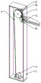
FIG. 1 is a schematic view of the appearance structure of the present invention;
FIG. 2 is a schematic sectional view of the side of the structure of the present invention;
FIG. 3 is a front sectional view of the structure of the present invention;
FIG. 4 is an enlarged view of the structure at A in FIG. 1;
FIG. 5 is an enlarged view of the structure at B in FIG. 2;
fig. 6 is an enlarged view of the structure at C in fig. 3.
In the figure: the lamp pole 1, lamp holder 2, spacing ring 3, motor 4, round bar 5, rope 6, wheel 7, bracing piece 8, bearing 9, slide 10, gag lever post 11, bar mouth 12, snap ring 13.
Detailed Description
In order to make the objects, technical solutions and advantages of the present invention clear and fully described, embodiments of the present invention are further described in detail below with reference to the accompanying drawings. It is to be understood that the specific embodiments described herein are merely illustrative of some embodiments of the invention and are not limiting of the invention, and that all other embodiments obtained by those of ordinary skill in the art without the exercise of inventive faculty are within the scope of the invention.
Example one
Referring to fig. 1-6, the present invention provides a technical solution: a street light facilitating service, the street light facilitating service comprising: the lamp comprises a lamp post 1, wherein a lamp holder 2 is arranged on the surface of the lamp post 1 in a sliding manner, and a limiting ring 3 is arranged at the bottom of a side plate of the lamp post 1; the motor 4 is arranged inside the lamp post 1, a round rod 5 is sleeved on an output shaft of the motor 4, and a rope 6 is wound on the surface of the round rod 5; and the wheel 7, the wheel 7 is rotatably arranged inside the lamp post 1 through a support rod 8 and a bearing 9, and the rope 6 is wound on the surface of a sliding plate 10 at the end part of the lamp holder 2 after passing around the wheel 7.
Connect on motor 4 output shaft's round bar 5 through 6 one end of rope, connect on the annular lug at slide 10 top behind the other end round wheel 7, motor 4 rotates to receive and release rope 6 and can realize the lift of lamp holder 2, carries on spacingly to lamp holder 2 through spacing ring 3, the size of gag lever post 11 and bar mouth 12, and simple structure safe and reliable, and lamp holder 2 adopts the integrated circuit board of complementary shape to be connected with slide 10 tightly, conveniently dismantles and changes lamp holder 2.
Example two
On the basis of the first embodiment, in order to realize the lifting of the lamp holder 2, the surface of the wheel 7 is provided with an annular groove, and a rope 6 is wound on the surface of the annular groove; two ends of the support rod 8 are respectively sleeved with a bearing 9, the bearings 9 are embedded in the side plates of the lamp post 1, two annular grooves are formed in the positions of two sides of the surface wheel 7 of the support rod 8, and clamping rings 13 are sleeved on the two annular grooves; one end of the rope 6 is tied on the annular groove on the surface of the round rod 5 and wound on the surface of the round rod, and the other end of the rope is tied on the annular lifting lug on the upper surface of the sliding plate 10 after passing through the wheel 7.
After the limiting rod 11 is taken down, the motor 4 is started, the motor 4 rotates to drive the round rod 5 on the output shaft of the motor 4 to rotate, the rope 6 is further wound on the surface of the round rod 5, the rope 6 pulls the wheel 7 to rotate so as to pull the annular lifting lug at the top of the sliding plate 10, the sliding plate 10 is pulled up, and the lamp holder 2 rises; or the rope 6 on the surface of the round rod 5 is released, and the lamp holder 2 descends slowly in coordination with the rotation of the round rod 5 under the action of the gravity of the lamp holder.
EXAMPLE III
On the basis of the second embodiment, in order to realize the locking of the position of the lamp holder 2, the lamp post 1 is a hollow square rod, a strip-shaped opening 12 is formed in a side plate of the lamp post 1, and the width of the strip-shaped opening 12 is gradually reduced at the bottom of the lamp post 1; the ring channel has been seted up on the surface of round bar 5, and rope 6 is established to the surface cover of ring channel, and a circular through-hole has been seted up to the tip of round bar 5 through the curb plate of lamp pole 1 and the tip of round bar 5, and the both sides of round bar 5 tip are provided with spacing ring 3 respectively, and spacing ring 3 and the circular through-hole department of round bar 5 tip run through there is gag lever post 11.
When the lamp holder 2 is lifted to the required height and then the position of the lamp holder 2 needs to be fixed, the limiting rod 11 is inserted from the inside of one limiting ring 3, penetrates through the circular through hole at the end part of the round rod 5 and then is inserted into the inside of the limiting ring 3 at the other side, so that the rotation of the round rod 5 and the output shaft of the motor 4 can be limited, and the position of the lamp holder 2 is fixed.
Example four
On the basis of the third embodiment, in order to realize the convenient disassembly, assembly and replacement of the lamp holder 2, an i-shaped platy bulge is arranged at the end part of the lamp holder 2, the end part of the lamp holder 2 is connected with a sliding plate 10, the sliding plate 10 is formed by connecting a small square plate between two large square plates, the width of the small square plate is equal to the width of the strip-shaped opening 12, the two large square plates are respectively clamped at two sides of a side plate of the lamp pole 1, an annular lifting lug is arranged on the upper surface of the large square plate at the inner side of the side plate of the lamp pole 1, a rope 6 is tied on the surface of the annular lifting lug, a platy bulge is arranged on the surface of the large square plate at the outer side of the side plate of the lamp pole 1, the shape of the platy bulge and the i-shaped platy bulge at the end part of the lamp holder 2 are complemented into a complete square plate, and the i-shaped platy bulge at the end part of the lamp holder 2 is inserted into the platy bulge at the inner part of the large square plate surface of the side plate at the outer side plate of the lamp pole 1 of the sliding plate 10.
When the lamp holder 2 breaks down, after the lamp holder 2 is lowered to the required height, the lamp holder 2 can be taken down only by pressing the sliding plate 10 and pushing the lamp holder 2 upwards, so that the lamp holder 2 is convenient to overhaul, in addition, a new lamp holder 2 can be directly installed, and the installation method and the disassembly method are the same, so that the lighting can be recovered more quickly.
When the lamp holder is actually used, after the limiting rod 11 is taken down, the motor 4 is started, the motor 4 rotates to drive the round rod 5 on the output shaft of the motor 4 to rotate, the rope 6 is wound on the surface of the round rod 5, the rope 6 pulls the wheel 7 to rotate so as to pull the annular lifting lug at the top of the sliding plate 10, the sliding plate 10 is pulled up, and the lamp holder 2 rises; or the rope 6 on the surface of the round rod 5 is released, and the lamp holder 2 slowly descends in coordination with the rotation of the round rod 5 under the action of the gravity of the lamp holder; when the lamp holder 2 is lifted to a required height and the position of the lamp holder 2 needs to be fixed, the limiting rod 11 is inserted from the inside of one limiting ring 3, penetrates through the circular through hole at the end part of the circular rod 5 and then is inserted into the inside of the limiting ring 3 at the other side, so that the rotation of the circular rod 5 and the output shaft of the motor 4 can be limited, and the position of the lamp holder 2 is fixed; when the lamp holder 2 breaks down, the lamp holder 2 is lowered to the required height, and the lamp holder 2 can be taken down only by pressing the sliding plate 10 and pushing the lamp holder 2 upwards, so that the lamp holder 2 is convenient to overhaul, in addition, a new lamp holder 2 can be directly installed, and the installation method and the disassembly method are the same, so that the lighting can be recovered more quickly; connect on motor 4 output shaft's round bar 5 through 6 one end of rope, connect on the annular lug at slide 10 top behind the other end round wheel 7, motor 4 rotates to receive and release rope 6 and can realize the lift of lamp holder 2, carries on spacingly to lamp holder 2 through spacing ring 3, the size of gag lever post 11 and bar mouth 12, and simple structure safe and reliable, and lamp holder 2 adopts the integrated circuit board of complementary shape to be connected with slide 10 tightly, conveniently dismantles and changes lamp holder 2.
Although embodiments of the present invention have been shown and described, it will be appreciated by those skilled in the art that changes, modifications, substitutions and alterations can be made in these embodiments without departing from the principles and spirit of the invention, the scope of which is defined in the appended claims and their equivalents.
Claims (7)
1. The utility model provides a street lamp convenient to overhaul which characterized in that: the street lamp convenient to overhaul includes:
the lamp comprises a lamp post (1), a lamp holder (2) is arranged on the surface of the lamp post (1) in a sliding mode, and a limiting ring (3) is arranged at the bottom of a side plate of the lamp post (1);
the lamp post is characterized by comprising a motor (4) arranged inside the lamp post (1), a round rod (5) is sleeved on an output shaft of the motor (4), and a rope (6) is wound on the surface of the round rod (5); and
the lamp post is characterized by comprising a wheel (7), the wheel (7) is rotatably arranged inside the lamp post (1) through a support rod (8) and a bearing (9), and a rope (6) winds on the surface of a sliding plate (10) at the end part of the lamp holder (2) after bypassing the wheel (7).
2. The street lamp convenient to overhaul as claimed in claim 1, wherein: the lamp pole (1) is a hollow square pole, the side plate of the lamp pole (1) is provided with a strip-shaped opening (12), and the width of the strip-shaped opening (12) is gradually reduced at the bottom of the lamp pole (1).
3. The street lamp convenient to overhaul as claimed in claim 1, wherein: the lamp holder is characterized in that an I-shaped platy bulge is arranged at the end part of the lamp holder (2), the end part of the lamp holder (2) is connected with a sliding plate (10), the sliding plate (10) is formed by connecting a small square plate between two large square plates, the width of the small square plate is equal to that of a strip-shaped opening (12), the two large square plates are respectively clamped at two sides of a side plate of the lamp pole (1), an annular lifting lug is arranged on the upper surface of the large square plate at the inner side of the side plate of the lamp pole (1), a rope (6) is tied on the surface of the annular lifting lug, platy bulges are arranged on the surface of the large square plate at the outer side of the side plate of the lamp pole (1), the platy bulges are complemented into a complete square plate with the I-shaped platy bulge at the end part of the lamp holder (2), and the I-shaped bulge at the end part of the lamp holder (2) is inserted into the platy bulge on the surface of the large square plate at the outer side plate of the lamp pole (1) at the sliding plate (10).
4. The street lamp convenient to overhaul as claimed in claim 1, wherein: the ring channel has been seted up on the surface of round bar (5), and rope (6) are established to the surface cover of ring channel, and a circular through-hole has been seted up to the tip that the curb plate that lamp pole (1) was run through to the tip of round bar (5), and the both sides of round bar (5) tip are provided with spacing ring (3) respectively, and the circular through-hole department of spacing ring (3) and round bar (5) tip runs through there is gag lever post (11).
5. The street lamp convenient to overhaul as claimed in claim 1, wherein: the surface of the wheel (7) is provided with an annular groove, and a rope (6) is wound on the surface of the annular groove.
6. The street lamp convenient to overhaul as claimed in claim 1, wherein: the lamp post is characterized in that two bearings (9) are respectively sleeved at two ends of the supporting rod (8), the bearings (9) are embedded in side plates of the lamp post (1), two annular grooves are formed in positions of two sides of the surface wheel (7) of the supporting rod (8), and clamping rings (13) are sleeved on the two annular grooves.
7. The street lamp convenient to overhaul as claimed in claim 1, wherein: one end of the rope (6) is tied on the annular groove on the surface of the round rod (5) and wound on the surface of the round rod, and the other end of the rope is tied on the annular lifting lug on the upper surface of the sliding plate (10) after bypassing the wheel (7).
Priority Applications (1)
| Application Number | Priority Date | Filing Date | Title |
|---|---|---|---|
| CN202222266301.1U CN218819821U (en) | 2022-08-29 | 2022-08-29 | Street lamp convenient to overhaul |
Applications Claiming Priority (1)
| Application Number | Priority Date | Filing Date | Title |
|---|---|---|---|
| CN202222266301.1U CN218819821U (en) | 2022-08-29 | 2022-08-29 | Street lamp convenient to overhaul |
Publications (1)
| Publication Number | Publication Date |
|---|---|
| CN218819821U true CN218819821U (en) | 2023-04-07 |
Family
ID=87253772
Family Applications (1)
| Application Number | Title | Priority Date | Filing Date |
|---|---|---|---|
| CN202222266301.1U Active CN218819821U (en) | 2022-08-29 | 2022-08-29 | Street lamp convenient to overhaul |
Country Status (1)
| Country | Link |
|---|---|
| CN (1) | CN218819821U (en) |
-
2022
- 2022-08-29 CN CN202222266301.1U patent/CN218819821U/en active Active
Similar Documents
| Publication | Publication Date | Title |
|---|---|---|
| CN202913758U (en) | Platform lifting type single tube communicating tower | |
| CN211289888U (en) | Urban road wisdom street lamp | |
| CN218819821U (en) | Street lamp convenient to overhaul | |
| CN203757643U (en) | Street-lamp mounting and dismounting device | |
| CN210639761U (en) | Flow guide device for intelligent traffic | |
| CN210107246U (en) | Street lamp capable of climbing | |
| CN209782466U (en) | Street lamp convenient to maintain and adjust | |
| CN205579368U (en) | Lifting street lamp | |
| CN111550739A (en) | Energy-saving multifunctional street lamp in smart city | |
| CN216769226U (en) | Convenient wisdom street lamp of maintaining | |
| CN113091007B (en) | Environment-friendly energy-saving street lamp convenient to overhaul | |
| CN115953910A (en) | Signal lamp for traffic control convenient to maintain | |
| CN216339146U (en) | Safety warning device for +/-500 kV converter substation construction site | |
| CN211925499U (en) | Light source liftable street lamp | |
| CN201568927U (en) | Ladder-type demountable street lamp post | |
| CN215597167U (en) | Street lamp convenient to change bill-board | |
| CN216307594U (en) | LED street lighting with billboard mounting structure | |
| CN211258471U (en) | Automatic extension ladder for electric power engineering maintenance | |
| CN209975398U (en) | Highway pilot lamp shell convenient to equipment | |
| CN217402511U (en) | Lamp pole convenient to maintenance street lamp | |
| CN110630961A (en) | Intelligent street lamp lighting device | |
| CN221444183U (en) | Lighting device convenient to maintenance | |
| CN213872546U (en) | Environment-friendly street lamp convenient to maintain | |
| CN216521294U (en) | Multifunctional lamp post structure | |
| CN211059993U (en) | Landscape lighting device |
Legal Events
| Date | Code | Title | Description |
|---|---|---|---|
| GR01 | Patent grant | ||
| GR01 | Patent grant | ||
| TR01 | Transfer of patent right | ||
| TR01 | Transfer of patent right |
Effective date of registration: 20231201 Address after: 225600 Southeast of the intersection of Xuefu Road and Qingqu Road in Songqiao Town, Gaoyou City, Yangzhou City, Jiangsu Province Patentee after: Yangzhou Yufeng Lighting Co.,Ltd. Address before: No. 10 Xinghai Road, Shihe Street, Puwan New District, Dalian City, Liaoning Province, 116,000 Patentee before: Zhu Weidong |