CN218817087U - Flame-proof type axial flow fan with protective structure - Google Patents
Flame-proof type axial flow fan with protective structure Download PDFInfo
- Publication number
- CN218817087U CN218817087U CN202222863727.5U CN202222863727U CN218817087U CN 218817087 U CN218817087 U CN 218817087U CN 202222863727 U CN202222863727 U CN 202222863727U CN 218817087 U CN218817087 U CN 218817087U
- Authority
- CN
- China
- Prior art keywords
- fixedly connected
- flow fan
- flame
- protective structure
- proof type
- Prior art date
- Legal status (The legal status is an assumption and is not a legal conclusion. Google has not performed a legal analysis and makes no representation as to the accuracy of the status listed.)
- Active
Links
Images

Classifications
-
- Y—GENERAL TAGGING OF NEW TECHNOLOGICAL DEVELOPMENTS; GENERAL TAGGING OF CROSS-SECTIONAL TECHNOLOGIES SPANNING OVER SEVERAL SECTIONS OF THE IPC; TECHNICAL SUBJECTS COVERED BY FORMER USPC CROSS-REFERENCE ART COLLECTIONS [XRACs] AND DIGESTS
- Y02—TECHNOLOGIES OR APPLICATIONS FOR MITIGATION OR ADAPTATION AGAINST CLIMATE CHANGE
- Y02E—REDUCTION OF GREENHOUSE GAS [GHG] EMISSIONS, RELATED TO ENERGY GENERATION, TRANSMISSION OR DISTRIBUTION
- Y02E10/00—Energy generation through renewable energy sources
- Y02E10/70—Wind energy
- Y02E10/72—Wind turbines with rotation axis in wind direction
Landscapes
- Structures Of Non-Positive Displacement Pumps (AREA)
Abstract
The utility model relates to a flame-proof type axial flow fan with protective structure belongs to flame-proof type axial flow fan technical field. It mainly if work in the rainy day of outdoor wind-blowing to current equipment, the debris that the impeller of equipment probably was blown up collide, probably can lead to damaging, also probably can lead to equipment short circuit after drenching with rain, the problem of unable work provides following technical scheme: the utility model provides a flame-proof type axial-flow fan with protective structure, includes the casing, the casing is connected with out the dryer, first small opening has been seted up to the dryer, the first hourglass net of inside fixedly connected with of first small opening. This application not only can let the flame-proof type axial fan who has protective structure block the debris of a bit more outside equipment through the design of tuber pipe isotructure, can also block the inside that the rainwater got into the flame-proof type axial fan who has protective structure, even if the rainwater enters also can be quick drop to the ground, can not contact inner structure and lead to the short circuit.
Description
Technical Field
The utility model relates to a flame-proof type circulation fan technical field especially relates to a flame-proof type circulation fan with protective structure.
Background
The explosion-proof axial flow fan is mainly used for ventilation in high-risk industries such as coal mines, industrial kilns and the like. The functions of ventilation or exhaust and the like can be still kept after an accident occurs. For example, in the explosion-proof axial-flow fan disclosed in chinese patent No. CN212250501U, if the device is operated outdoors in a windy and rainy day, the impeller of the device may be collided by blown-up impurities, which may cause damage, and the device may be short-circuited after being rained, which may not operate.
SUMMERY OF THE UTILITY MODEL
The utility model aims at providing a flame-proof type axial flow fan with protective structure to the problem that exists among the background art.
The technical scheme of the utility model: the utility model provides a flame-proof type axial flow fan with protective structure, includes the casing, the casing is connected with out the dryer, first small opening has been seted up to the dryer, the first hourglass net of the inside fixedly connected with of first small opening, the first cover that keeps off of the inside fixedly connected with of play dryer, the first baffle of play dryer fixedly connected with, casing fixedly connected with air inlet section of thick bamboo, the second small opening has been seted up to the air inlet section of thick bamboo, the inside fixedly connected with second of second small opening leaks the net, the inside fixedly connected with second of air inlet section of thick bamboo keeps off the cover, air inlet section of thick bamboo fixedly connected with second baffle.
Preferably, the clamping groove is formed in the air outlet cylinder, and the clamping block of the clamping groove is clamped into the inner wall of the shell.
Preferably, the outer wall fixedly connected with bolt piece of casing, the activity hole has been seted up to the bolt piece, activity hole swing joint has the bolt, the through hole has been seted up to the exhaust fan, the one end activity of bolt is run through behind the casing card and is gone into the through hole.
Preferably, the outer surface of the bolt is movably sleeved with a spring, and the bolt is fixedly connected with a connecting block for preventing the bolt from falling off the movable hole.
Preferably, the inner wall of the shell is fixedly connected with a plurality of check blocks for limiting the air outlet cylinder to move towards the shell.
Preferably, an impeller is connected to the inside of the housing.
Compared with the prior art, the beneficial effects of the utility model are that:
(1): through the design of the structures such as the air outlet cylinder, the explosion-proof axial flow fan with the protection structure can not only block larger sundries out of the equipment, but also prevent rainwater from entering the inside of the explosion-proof axial flow fan with the protection structure, so that the rainwater can quickly fall to the ground even if entering the explosion-proof axial flow fan, and the short circuit caused by the contact of the internal structure can be avoided;
(2): this application can be with the quick dismantlement in the play dryer follow casing through the design of latch piece isotructure, later just can maintain or clean convenient and fast to the structure in the casing.
Drawings
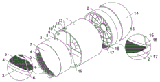
FIG. 1 is a schematic structural diagram of an explosion-proof axial-flow fan with a protective structure;
FIG. 2 is a cross-sectional view of the plunger block of FIG. 1;
FIG. 3 is a cross-sectional view of the housing of FIG. 1;
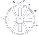
fig. 4 is a left side view of the housing of fig. 1.
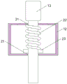
Reference numerals are as follows: 1. a housing; 2. an air inlet cylinder; 3. an air outlet cylinder; 4. a first shield; 5. a first leaky net; 6. a first leak groove; 7. a first baffle plate; 8. a through hole; 9. a card slot; 10. a stopper; 11. a clamping block; 12. a latch block; 13. a bolt; 14. a second baffle; 15. a second shield; 16. a second leak groove; 17. a second leaky network; 19. an impeller; 21. a movable hole; 22. a spring; 23. and (4) connecting the blocks.
Detailed Description
The technical solution of the present invention will be further explained with reference to the accompanying drawings and specific embodiments.
Example one
As shown in fig. 1-3, the utility model provides a flame-proof type axial-flow fan with protective structure, including casing 1, the internally mounted of casing 1 has impeller 19, impeller 19 is driven by the electric motor who installs in casing 1, four restrictions play dryer 3 of the inner wall fixedly connected with of casing 1 move the dog 10 in to casing 1, casing 1 is connected with play dryer 3, first small opening 6 has been seted up to play dryer 3, the first small opening 5 of the inside fixedly connected with of first small opening 6, the first fender cover 4 of the inside fixedly connected with of play dryer 3, play dryer 3 fixedly connected with first baffle 7, casing 1 fixedly connected with air inlet cylinder 2, second small opening 16 has been seted up to air inlet cylinder 2, the inside fixedly connected with second small opening 17 of second small opening 16, the inside fixedly connected with second baffle 15 of air inlet cylinder 2, air inlet cylinder 2 fixedly connected with second baffle 14, play dryer 3 has seted up draw-in groove 9, the inner wall fixedly connected with card of casing 1 goes into the fixture block 11 of draw-in groove 9.
The working principle of the embodiment is as follows: when wind blows and rains, rainwater is blocked by the first baffle 7 and the second baffle 14, some rainwater can be blown by wind and fall into the air outlet cylinder 3 and the air inlet cylinder 2, and the rainwater can drip onto the ground from the small holes of the first leakage net 5 and the second leakage net 17; when wind blows sundries into the shell 1, the sundries are blocked outside the shell 1 by the first blocking cover 4 and the second blocking cover 15, and the impeller 24 inside the shell 1 is protected from colliding with the sundries to cause damage.
Example two
As shown in fig. 1-3, the utility model provides a flame-proof type axial-flow fan with protective structure, including casing 1, the internally mounted of casing 1 has impeller 19, impeller 19 is driven by the electric motor who installs in casing 1, four restrictions play dryer 3 of the inner wall fixedly connected with of casing 1 move the dog 10 in to casing 1, casing 1 is connected with play dryer 3, first small opening 6 has been seted up to play dryer 3, the first small opening 5 of the inside fixedly connected with of first small opening 6, the first fender cover 4 of the inside fixedly connected with of play dryer 3, play dryer 3 fixedly connected with first baffle 7, casing 1 fixedly connected with air inlet cylinder 2, second small opening 16 has been seted up to air inlet cylinder 2, the inside fixedly connected with second small opening 17 of second small opening 16, the inside fixedly connected with second baffle 15 of air inlet cylinder 2, air inlet cylinder 2 fixedly connected with second baffle 14, play dryer 3 has seted up draw-in groove 9, the inner wall fixedly connected with card of casing 1 goes into the fixture block 11 of draw-in groove 9.
As shown in fig. 1 and fig. 4, compared with the first embodiment, the present embodiment further includes: outer wall fixedly connected with bolt piece 12 of casing 1, activity hole 21 has been seted up to bolt piece 12, and activity hole 21 swing joint has bolt 13, and spring 22 has been cup jointed in the surface activity of bolt 13, and bolt 13 fixedly connected with prevents that bolt 13 from deviating from the connecting block 23 of activity hole 21, and through hole 8 has been seted up to play dryer 3, and through hole 8 has been gone into to the one end activity of bolt 13 after running through casing 1.
The working principle of the embodiment is as follows: when needing to maintain or clean the inside structure of flame-proof type axial flow fan that has protective structure, upwards stimulate bolt 13 earlier, take out play dryer 3 from casing 1, later just can maintain or clean casing 1 inside, after the maintenance or clean, put into casing 1 with play dryer 3, make fixture block 11 card go into draw-in groove 9, upwards stimulate bolt 13, later with going out dryer 3 push into casing 1 in, move to the outer edge contact dog 10 that goes out dryer 3, loosen bolt 13 this moment, connecting block 23 receives an elastic thrust of spring 22 and moves down, connecting block 23 drives bolt 13 and moves down, make the one end card of bolt 13 go into through hole 8, it just can't rotate in first fender cover 4 to go out dryer 3.
Exemplary embodiments of the solution proposed in the present application have been described in detail above with reference to preferred embodiments, however, it will be understood by those skilled in the art that many variations and modifications may be made to the specific embodiments described above, and that many combinations of the various features, structures and characteristics presented in the present application may be made without departing from the concept of the present application, the scope of which is defined in the appended claims.
Claims (6)
1. The utility model provides a flame-proof type axial flow fan with protective structure, includes casing (1), its characterized in that: the improved air-conditioning fan is characterized in that the shell (1) is connected with an air outlet cylinder (3), a first leakage groove (6) is formed in the air outlet cylinder (3), a first leakage net (5) is fixedly connected to the inside of the first leakage groove (6), a first blocking cover (4) is fixedly connected to the inside of the air outlet cylinder (3), a first baffle (7) is fixedly connected to the air outlet cylinder (3), the shell (1) is fixedly connected with an air inlet cylinder (2), a second leakage groove (16) is formed in the air inlet cylinder (2), a second leakage net (17) is fixedly connected to the inside of the second leakage groove (16), a second blocking cover (15) is fixedly connected to the inside of the air inlet cylinder (2), and a second baffle (14) is fixedly connected with the air inlet cylinder (2).
2. The flameproof axial-flow fan with the protective structure according to claim 1, wherein the air outlet cylinder (3) is provided with a clamping groove (9), and a clamping block (11) clamped into the clamping groove (9) is fixedly connected to the inner wall of the housing (1).
3. The flame-proof type axial-flow fan with the protection structure is characterized in that a plug block (12) is fixedly connected to the outer wall of the shell (1), a movable hole (21) is formed in the plug block (12), a plug (13) is movably connected to the movable hole (21), a through hole (8) is formed in the air outlet cylinder (3), and one end of the plug (13) penetrates through the shell (1) movably and then is clamped into the through hole (8).
4. The flameproof axial-flow fan with the protective structure according to claim 3, wherein a spring (22) is movably sleeved on the outer surface of the bolt (13), and the bolt (13) is fixedly connected with a connecting block (23) which prevents the bolt (13) from falling out of the movable hole (21).
5. The flameproof axial-flow fan with the protective structure according to claim 1, characterized in that the inner wall of the housing (1) is fixedly connected with a plurality of stoppers (10) that limit the movement of the air outlet cylinder (3) into the housing (1).
6. The flameproof axial-flow fan with the protective structure according to claim 1, characterized in that the inside of the housing (1) is connected with an impeller (19).
Priority Applications (1)
| Application Number | Priority Date | Filing Date | Title |
|---|---|---|---|
| CN202222863727.5U CN218817087U (en) | 2022-10-29 | 2022-10-29 | Flame-proof type axial flow fan with protective structure |
Applications Claiming Priority (1)
| Application Number | Priority Date | Filing Date | Title |
|---|---|---|---|
| CN202222863727.5U CN218817087U (en) | 2022-10-29 | 2022-10-29 | Flame-proof type axial flow fan with protective structure |
Publications (1)
| Publication Number | Publication Date |
|---|---|
| CN218817087U true CN218817087U (en) | 2023-04-07 |
Family
ID=87256504
Family Applications (1)
| Application Number | Title | Priority Date | Filing Date |
|---|---|---|---|
| CN202222863727.5U Active CN218817087U (en) | 2022-10-29 | 2022-10-29 | Flame-proof type axial flow fan with protective structure |
Country Status (1)
| Country | Link |
|---|---|
| CN (1) | CN218817087U (en) |
-
2022
- 2022-10-29 CN CN202222863727.5U patent/CN218817087U/en active Active
Similar Documents
| Publication | Publication Date | Title |
|---|---|---|
| CN109586175B (en) | But quick assembly disassembly's switch board | |
| CN218817087U (en) | Flame-proof type axial flow fan with protective structure | |
| CN203010856U (en) | Air pipe structure with rain-proof function | |
| CN213450723U (en) | Hydrology water resource water pump motor protection device | |
| CN214626040U (en) | Rainproof dustproof heat dissipation GRC outdoor distribution box | |
| CN207660863U (en) | A kind of centrifugal blower with air purifying function | |
| CN213577903U (en) | New fan of wall formula with remove haze function | |
| CN209710518U (en) | A kind of hydraulic engineering electric control box | |
| CN207782168U (en) | A kind of electrical Installation cabinet | |
| CN211059010U (en) | Roots blower for internal combustion engine | |
| CN216814677U (en) | Air source heat pump protection casing | |
| CN217152274U (en) | Double-loop cooling water device for circulating water pump motor of thermal power plant | |
| CN216199118U (en) | Negative-pressure air fan with protection function | |
| CN213235485U (en) | Air exhaust device of air compressor | |
| CN216366441U (en) | Wisdom fire control thing allies oneself with switch board | |
| CN210003560U (en) | kinds of exhaust fan | |
| CN212137040U (en) | Safe block terminal for construction | |
| CN219474697U (en) | Environmental monitoring instrument protector | |
| CN217010082U (en) | Outdoor interim block terminal | |
| CN216087198U (en) | Intelligent PLC control cabinet with explosion-proof function | |
| CN220798869U (en) | Debugging cabinet for power engineering | |
| CN210921700U (en) | Ventilation unit that factory building fitment adopted | |
| CN217082831U (en) | Negative pressure smoke exhaust device for fire engineering | |
| CN213899424U (en) | Energy-conserving fan convenient to it is clean | |
| CN212057549U (en) | Air inlet protector of household purifier |
Legal Events
| Date | Code | Title | Description |
|---|---|---|---|
| GR01 | Patent grant | ||
| GR01 | Patent grant |